Design Purpose:
To design a keyboard that suits your personal usage habits. This involves designing a keyboard specifically tailored to your own habits and needs. It might have an unusual layout, a unique height, or unconventional key functions, but no matter how unusual it may seem, it's a structure and function specifically designed for your needs. This is perhaps the charm of customization.
Detailed production tutorial (see attachment).

Design Requirements:
Layout, Customizable
, Cool RGB
Keys, Online Key Customization
Support, Macro Definitions,
Hot-swappable
Type-C Interface.
Hardware Selection
: Controller: STM32F103/APM32F103
, LEDs: WS2812B (6028 reverse-mount 4-pin),
Switches: Kailh.
Software Development:
QMK Firmware
(Vial).
Hardware Design:
Controller:
Considering support for Vial firmware and various lighting effects, a high-performance 32-bit microcontroller was chosen. The domestic APM32F103CBT6 was selected.
The minimum system of the APM32 is relatively simple, requiring only necessary power supply, clock, and a reset button.
It's important to note that when flashing the firmware after creation, a bootloader is used. To avoid re-flashing the bootloader after each firmware update, boot0 must be grounded.

The power supply is crucial; considering the keyboard's small size, the chosen LDO chip , the RT9193, is selected for its
minimal external circuitry and compact design. The mainstream Type-C interface is used for easy connection. Because the keyboard communicates with the computer via USB, the USB_D+ needs to be pulled up with a 1.5k resistor according to design requirements. Why is a pull-up resistor necessary, and specifically 1.5k? Refer to online resources for an explanation: How does the USB host detect the inserted device? On each downstream port of the USB hub, a 15K pull-down resistor is connected to ground on D+ and D-. This way, when the hub port is floating and no device is plugged in, the input is pulled low by these two pull-down resistors. On the USB device side, a 1.5K pull-up resistor is connected to 3.3V power supply on either D+ or D-. Whether the 1.5K pull-up resistor is connected to D+ or D- depends on the device speed. For full-speed and high-speed devices, the pull-up resistor is connected to D+, while for low-speed devices, the pull-up resistor is connected to D-. When a device is plugged into the hub, the voltage on the data line connected to the pull-up resistor is determined by the voltage division of the 1.5K pull-up and 15K pull-down resistors, resulting in approximately 3V (3.3/1.5+15)*1.5=3V). This is a high-level signal for the hub's receiver. Upon detecting this state, the hub reports it to the USB host controller, thus detecting the device insertion. The hub determines the speed type of the inserted device based on whether the pulled-up data line is D+ or D-. High-speed USB devices are initially identified as full-speed devices. After confirmation through communication between the hub and the device, it switches to high-speed mode. In high-speed mode, current transmission is used, and the pull-up resistor on D+ is disconnected. If this 1.5K value is different, the voltage level after the D+/D- pull-up division will change. If voltage ripple is encountered, it may not be detected; this is the origin of the 1.5K value. The buttons are hot-swappable and use Kailh hot-swappable connectors. Keyboard key connections generally fall into two categories: 1. Matrix connection and 2. Independent connection. The goal of this design is to create a small-array keyboard, and since the AMP32 has sufficient I/O ports, an independent connection is adopted. This method eliminates the need for diodes, reducing costs. The LEDs are driven by WS2812B (6028 reverse-mount 4-pin) via PWM signals. The LEDs are connected in series. During the design, remember to connect the signal input pins to the pins on the microcontroller that can output PWM signals. Do n't forget to reserve the programming pins. ST-LINK is recommended for programming. For the keyboard firmware design , based on the initial keyboard requirements, instead of developing our own, we chose the open-source keyboard firmware QMK. We also used VIAL instead of VIA. This is why a higher-performance chip was chosen. Note that because VIAL is used, you need to download the code from the corresponding VIAL branch, not the main repository. The vial_qmk source code and VIAL tutorial are available on the QMK website. It supports various keyboards and features such as knobs and screens. This design only uses the most basic key functions. This is a small, practical layout. The development environment first requires the QMK MSYS software. QMK maintains a package based on MSYS2, with all command-line programs and dependencies included. The development environment can be quickly started using QMK MSYS shortcut commands. Next, you need to obtain the QMK source code. Due to certain reasons, please resolve network issues yourself. When obtaining the source code, because the project contains many submodules, it is not recommended to download each submodule individually via Git. Note that directly downloading a ZIP file from the GitHub web interface can also result in incomplete submodule downloads. It is recommended to use the GitHub desktop application for downloading; this method eliminates the need to consider the impact of submodules. After obtaining the source code, test your development environment using QMK MSYS. For example, the following code: `qmk compile -kb clueboard/66/rev3 -km default`. If you see no errors and the .hex file is successfully generated, the development environment is set up and you can proceed with further development. Linking: `.build/clueboard_66_rev3_default.elf [OK] Creating load file for flashing: `.build/clueboard_66_rev3_default.hex [OK]`


Copying clueboard_66_rev3_default.hex to the qmk_firmware folder [OK]
Checking the file size of clueboard_66_rev3_default.hex [OK]
* The firmware size is fine - 26356/28672 (2316 bytes free)
Code writing:
Open the QMK source code with any code editor.
The QMK project structure is as follows:
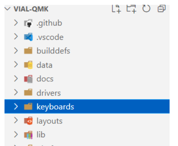
We only care about the contents of the keyboards folder, which contains many other keyboards developed by others, and we can also use them for reference.
Create the following
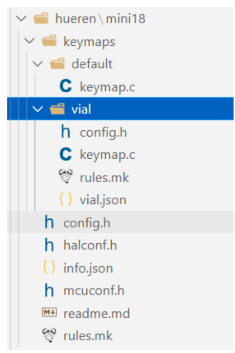
file structure
under the keyboards folder
:
... Run `python3 util/vial_generate_keyboard_uid.py` from the root directory of vial-qmk to generate a unique Vial keyboard ID. Ensure your computer has a Python environment. `#pragma once define VIAL_KEYBOARD_UID {0x9A, 0x27, 0xBD, 0x85, 0x42, 0xBD, 0x97, 0x56} keymap.c` is the same as above . `rules.mk` is used to enable Vial under the rules: `VIAL VIA_ENABLE = yes` ` VIAL_ENABLE = yes` ` VIAL_INSECURE = yes` `VIALRGB_ENABLE = yes` `vial.json` The first step in creating the Vial port is to prepare the keyboard definition, which is a JSON file describing the keyboard layout. Fill in the corresponding content according to the following template: `{ "lighting": "vialrgbe", "matrix": { "rows": 4, "cols": 4 }, "layouts": { "keymap": } }` The content of `keymap` needs to be retrieved from the keyboard design website. Enter the corresponding coordinates on the blank keyboard. After filling in the coordinates as shown in the image below, copy the contents of the Raw data file and paste them into it . Configure the number of LEDs, DMA channels, and other related settings in config.h . Refer to the manual for detailed configuration instructions. // Copyright 2023 HiryKun (@HiryKun) // SPDX-License-Identifier: GPL-2.0-or-later pragma once define BOOTMAGIC_LITE_ROW 0 define BOOTMAGIC_LITE_COLUMN 3 define WS2812_PWM_DRIVER PWMD2 define WS2812_PWM_CHANNEL 4 define WS2812_DMA_STREAM STM32_DMA1_STREAM2 define WS2812_DMA_CHANNEL 2 define RGB_MATRIX_LED_COUNT 15 define RGB_MATRIX_FRAMEBUFFER_EFFECTS define RGB_MATRIX_KEYPRESSES define NO_USB_STARTUP_CHECK halconf.h to enable the STM32 function. #define HAL_USE_PWM TRUE #define HAL_USE_PAL TRUE define STM32_HAS_USB TRUE include_next info.json The main keyboard configuration corresponds to the physical connections between the keys and the microcontroller pins. It is written in matrix form, with NO_PIN used to fill in missing keys. "matrix_pins": { "direct":[ ["B14","B15","B5","B3"],


["B13","B12","B1","A7"],
["B0","NO_PIN","NO_PIN","NO_PIN"],
["A6","NO_PIN","NO_PIN","NO_PIN"]
]
},
Keyboard layout definition. The layout should be consistent with the previously designed layout.
"layouts": {
"LAYOUT": {
"layout": [
{"matrix": [0, 0],"x": 0,"y": 0},
{"matrix": [0, 1],"x": 1,"y": 0},
{"matrix": [0, 2],"x": 2,"y": 0},
{"matrix": [0, 3],"x": 3,"y": 0},
{"matrix": [1, 0],"x": 0,"y": 1},
{"matrix": [1, 1],"x": 1,"y": 1},
{"matrix": [1, 2],"x": 2,"y": 1},
{"matrix": [1, 3],"x": 3,"y": 1,"h": 2},
{"matrix": [2, 0],"x": 0,"y": 2,"w": 2},
{"matrix": [3, 0],"x": 0,"y": 3,"h": 2}
]
}
}
RGB related configuration
lighting effects. Enter the lighting effects you want to enable here.
The more lighting effects, the larger the firmware size, so choose a high-performance microcontroller initially.
"animations": {
"alphas_mods": true,
"gradient_up_down": true,
"gradient_left_right": true,
"breathing": true,
"band_sat": true,
"band_val": true,
"band_pinwheel_sat": true,
"band_pinwheel_val": true,
"band_spiral_sat": true,
"band_spiral_val": true,
"cycle_all": true,
}
Illuminator position settings. For detailed instructions, please refer to the document
"center_point": [32,32],
"layout": [
{"flags": 4, "matrix": [1,0], "x": 0, "y": 0},
{"flags": 4, "matrix": [1,1], "x": 21, "y": 0},
{"flags": 4, "matrix": [1,2], "x": 43, "y": 0},
{"flags": 4, "matrix": [1,3], "x": 64, "y": 0},
{"flags": 4, "matrix": [2,3], "x": 64, "y": 21},
{"flags": 4, "matrix": [2,2], "x": 43,{"y": 21},
{"flags": 4, "matrix": [2,1], "x": 21, "y": 21},
{"flags": 4, "matrix": [2,0], "x": 0, "y": 21},
{"flags": 4, "matrix": [3,0], "x": 0, "y": 43},
{"flags": 4, "matrix": [3,1], "x": 21, "y": 43}
]
RGB drive signal output pin
"ws2812": {
"driver": "pwm",
"pin": "A3"
}
mcuconf.h
mainly enables the peripherals needed by STM32
#include_next
undef STM32_PWM_USE_TIM2
define STM32_PWM_USE_TIM2 TRUE
undef The basic keyboard firmware code is now defined as STM32_PWM_USE_TIM1 TRUE. After compilation using QMK MSYS, firmware in .BIN and .HEX formats can be generated
.


 京公网安备 11010802033920号

 100-SP3-T1-B4-M5-R-E-HDW15


