The Mechanical Flower is a globally acclaimed open-source project
, originally created by a foreigner. It uses copper wire as a framework, with LEDs soldered to it and controlled by servo motors, resulting in a mechanical flower that automatically opens and closes, changing colors in a cyberpunk style. However, it is difficult to manufacture, mass-produce, and has low reliability. This project is a derivative work based on the open-source project, utilizing modules from the LCSC PCB and SMT ecosystem to create a mechanical flower product with a copper wire framework, possessing aesthetic value.
Project Functionality:
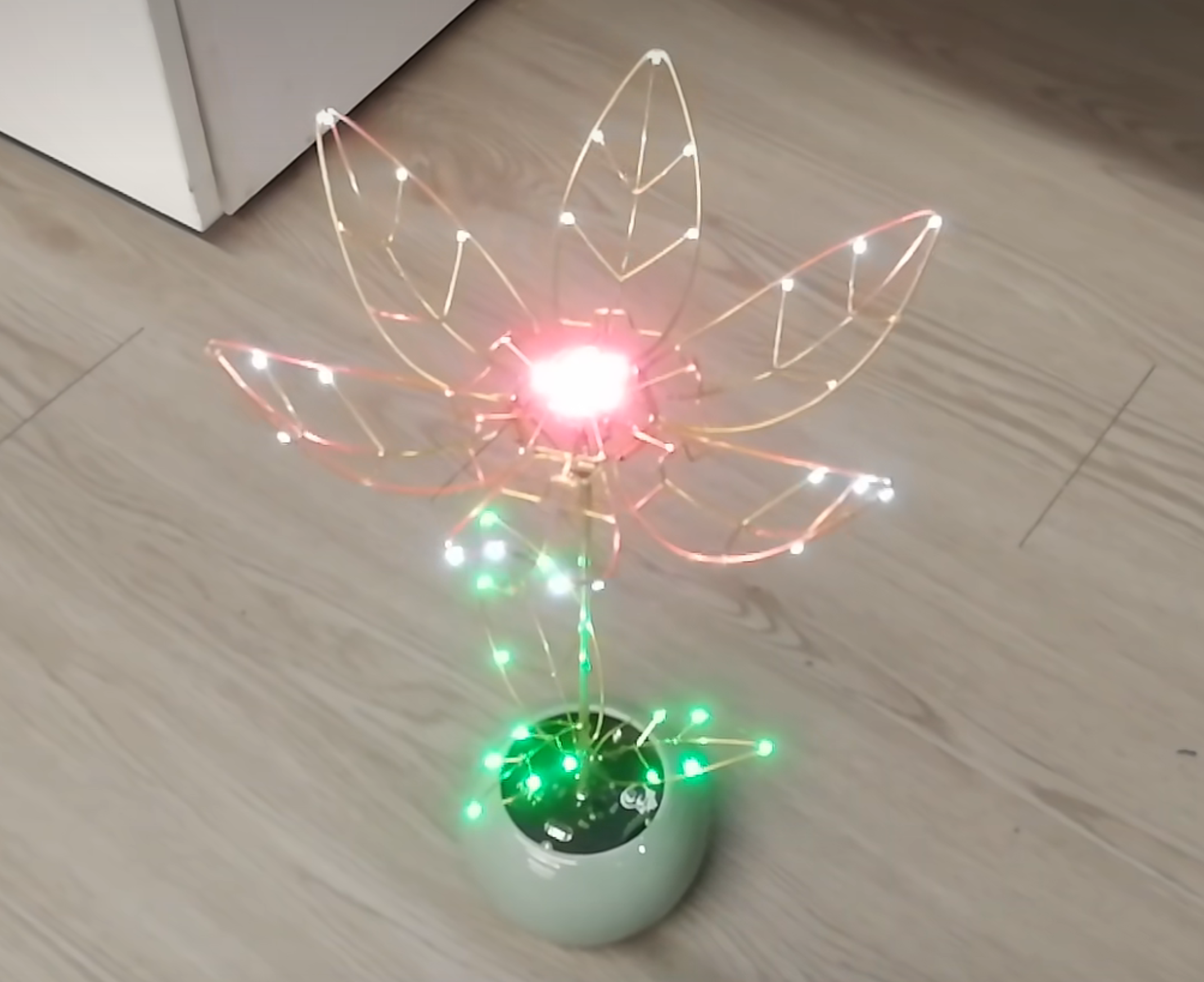
The project incorporates a microwave radar module or touch module. When someone approaches or touches the leaves, the mechanical flower automatically "opens," with the white LEDs on the petals gradually brightening during the opening process. The flower core can be any color, and the petals display a pleasing color. After fully opening, it automatically "closes" after a short wait, with the white LEDs on the petals gradually dimming during the closing process. The green LEDs on the leaves below the mechanical flower also gradually brighten and dim during the opening and closing process. It is rechargeable; during charging, the leaves of the mechanical flower will exhibit a breathing and flashing dynamic effect. The mechanical flower has a very beautiful effect and can be used as a lobby decoration or a birthday gift. It has a certain commercial value.
Project attributes:
I have not participated in any competitions. Design
principle
: PWM control of programmable LED, PWM control of servo motor, and code design of STM8 microcontroller.
Software description:
In terms of control, there is a microcontroller version and a pure hardware version, which reflects my software and hardware design capabilities. I am a hardware engineer and my software foundation is relatively weak. In this project, the software mainly uses basic statements such as WHILE, if, etc., and uses the interrupt system to complete the display of the project effect. The code can currently achieve basic functions, but there are still some bugs, such as
(1) when the power is cut off in the non-closed state, the MCU will not remember the original position of the servo motor. After power is restored, it will quickly reset, causing the mechanical flower to accelerate very fast, affecting durability and ornamental value.
(2) The hardware has reserved a lot of peripheral power control. In fact, the code has not yet optimized power consumption and has not yet implemented sleep instructions.
(3) The problem may be due to coding ability or low MCU frequency. When controlling the servo and LED gradient, the servo appears to be jittery, and the LED gradient effect is poor
. I hope that programming experts can optimize and improve this. I apologize for my limited ability!
Physical display
of the pink mechanical flower with copper wire skeleton
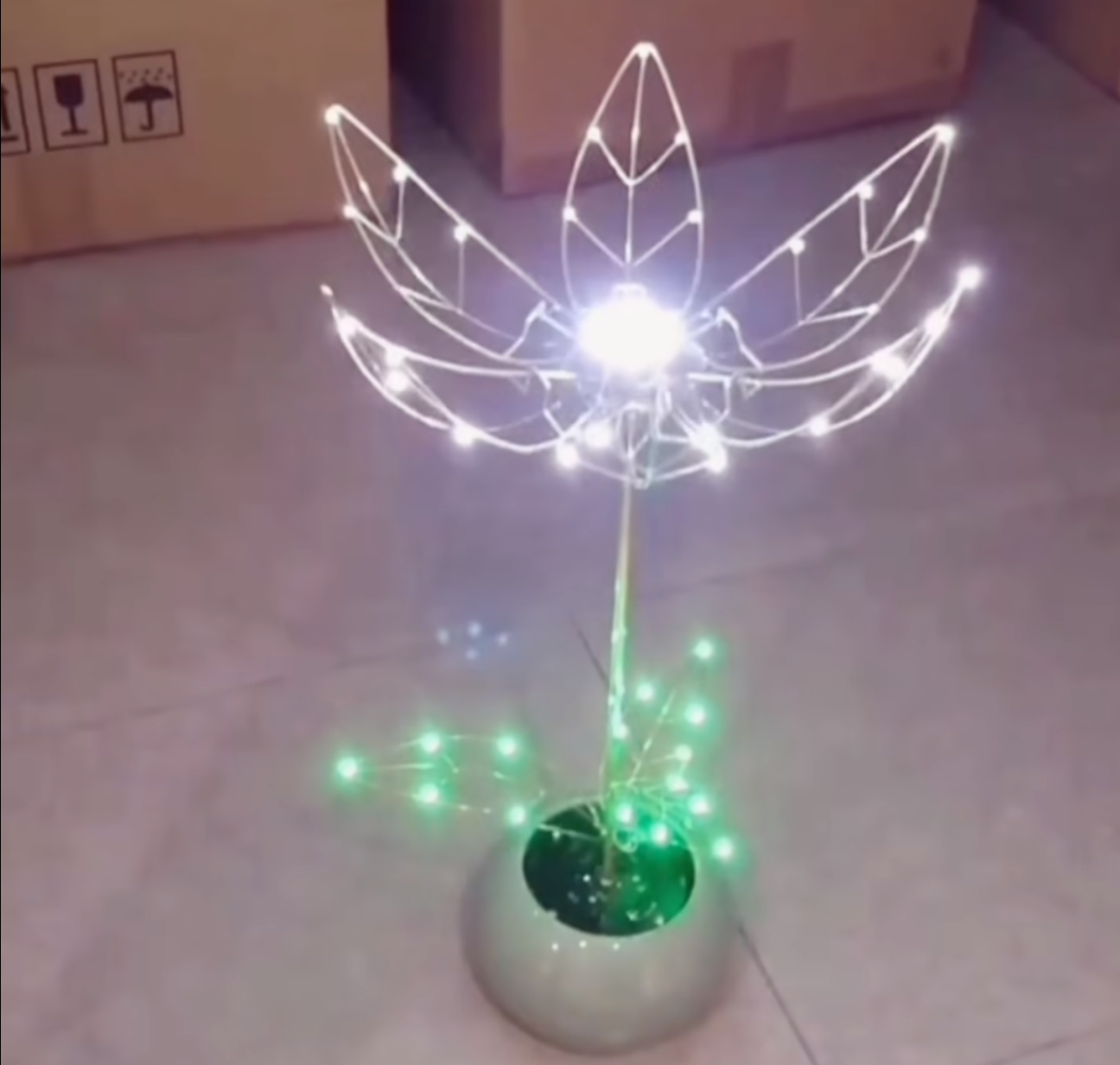
The flowering effect of the white mechanical flower with copper wire skeleton
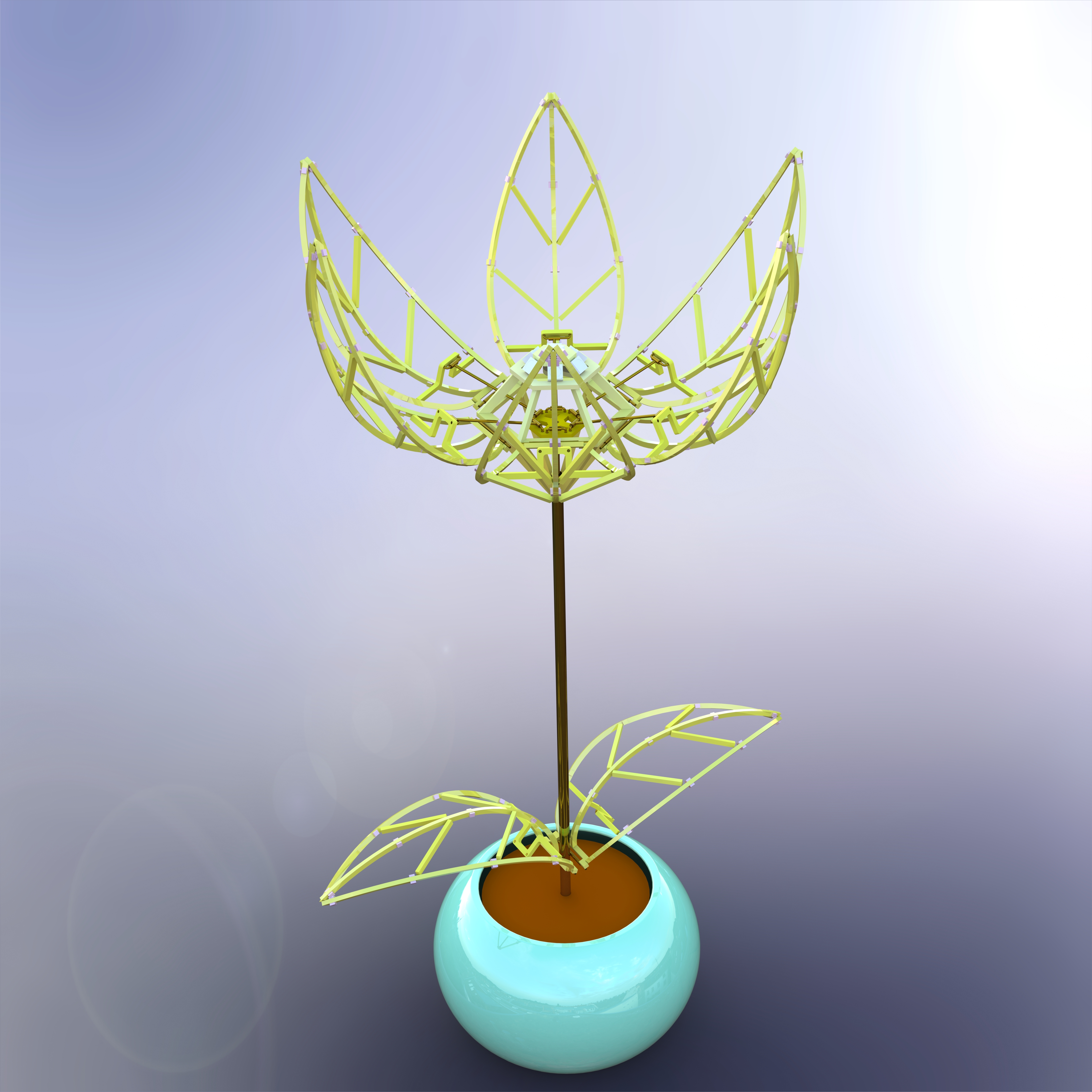
Solidworks modeled PCB skeleton mechanical flower, rendering, no physical object yet. Since JLCPCB does not support PCB production with a width of less than 5mm, the development of this PCB version of the mechanical flower will not be started for the time being.
3D printed exoskeleton version of the mechanical flower, rendering, under development.

Design considerations
Limit the DC motor or servo or connect the PTC coil resistor in series to the motor power supply to avoid program deviation during debugging, which may damage the work.
Other
works demonstration 1: [Loving you is like loving life, I give you a flower that will never wither, I will never part from you until the mountains have no edges and the heavens and earth are united! [
Demonstration 2: Mechanical Flower] [
Demonstration 3: Mechanical Flower PCB Version Solidworks Modeling, 2.5 Days of Practice, Preparing to Get Free JLCPCB Modeling] [Demonstration 4: Mechanical Flower PCB Version Solidworks Modeling, 2.5 Days of Practice, Preparing to Get Free JLCPCB
Modeling] [Demonstration 5: Application Revealed Next Episode! It's Here!] -Bilibili】 https://b23.tv/gGxfAry
Spark Competition Video: 【No entry for those with clumsy hands! Copper wire mechanical flower, basic operation for handicraft masters? -Bilibili】 https://b23.tv/LmfGjxb
Other material links (I bought them when I made them myself, for reference only)
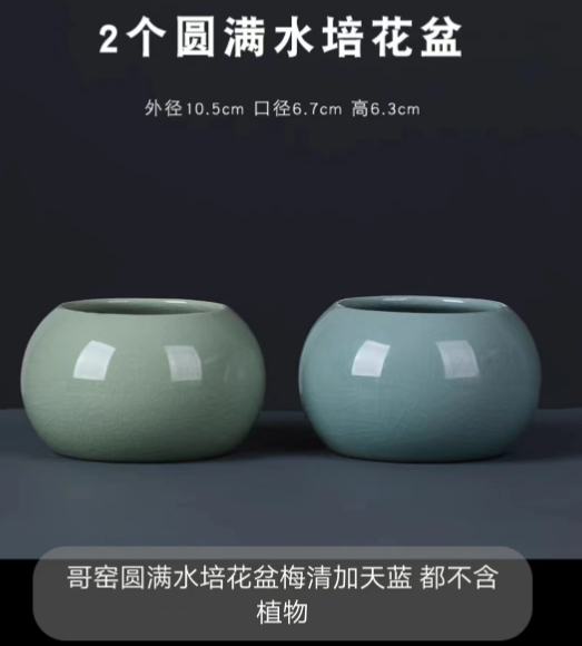
(1) Flower pot: 【Taobao】 https://m.tb.cn/h.UFvdfVX?tk=l8pfdNbk5zN CZ3457 "Ceramic Ge Kiln Crack Ceramic Hydroponic Small Flower Pot No-hole Flower Pot Green Plant Container Fresh Desktop Flower Vase Clearance" Click the link to open directly or search on Taobao to open directly to
buy the size outer diameter 10.5cm, 6.7cm mouth diameter, and 6.3mm height.
(2) Copper wire: [Taobao] https://m.tb.cn/h.UuCizlA?tk=1Xs5dNbU6EM CZ3457 "Half-jin pack, free shipping H65 brass wire, semi-hard and soft texture, 0.15 0.2 0.3 0.35-8mm pure brass wire" Click the link to open directly or search on Taobao to open Huaban
: Buy 1.0 half jin of H65 brass wire ≈ 37 meters (semi-hard), use with a sleeve. The outer diameter of the copper tube of the sleeve below is 1.6mm, and the inner diameter is 1.6-0.2*2=1.2mm. If the diameter difference between the sleeve and the copper wire is too large, the mechanical opening and closing process will not be smooth. If the diameter difference is too small, it cannot be inserted or cannot move.

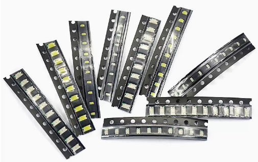
(3) Petal LED + Green Leaf LED: [Taobao] https://m.tb.cn/h.UuVicl6?tk=66OFdNbSMtE CZ3457 "Surface Mount LED 0402 0603 0805 1206 Red Yellow Blue Green White High Brightness LED Beads Light Emitting Diode" Click the link to open directly or search on Taobao to open
the LEDs on the petals. Buy 0805 for easier soldering, at least 30 pieces. White light makes the flowers look pure. Other colors are also acceptable, depending on personal preference. For
the LEDs on the green leaves, also buy 0805, usually emerald green, at least 15 pieces.
(4) Servo:
Buy 0-180°, MG90S (all metal), 1 piece, [Taobao] https://m.tb.cn/h.UuVcARt?tk=2gS1dNbcyS9 CZ3457 "SG90 MG90S 9g servo 450 helicopter fixed-wing model remote control airplane 9g motor model" Click the link to open directly or search on Taobao to open directly

(5) Battery: [Taobao] https://m.tb.cn/h.UGjM35u?tk=2YMUdNbNy8b CZ0001 "902040 rechargeable 602040 large capacity 3.7V lithium battery Bluetooth speaker barcode scanner 1000mAh milliampere core" Click the link to open directly or search on Taobao to open directly
Buy 1000mAh, size as follows:

(6) Programmable LEDs: [Taobao] https://m.tb.cn/h.UuCn94G?tk=bCJudNbj6S8CZ0001 "WS2812B Full-Color High-Brightness RBG 5050 SMD Programmable LED 5V Strip Light for Brushless Racing Drones" Click the link to open directly or search on Taobao to
buy WS2812B, at least 7 LEDs required.

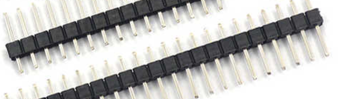
(7) Pin header: [Taobao] https://m.tb.cn/h.UGjJI44?tk=hizjdNbKhRk CZ3457 "Single row pin, double row pin, copper pitch 2.54MM 1*2/3/4/5/6/7/8/10/12/20/30P gold-plated pins" Click the link to open directly or search on Taobao to
buy longer ones. You can cut different PIN numbers yourself. The pitch is 2.54mm.
(8) Microwave module (choose one from touch module): [Taobao] https://m.tb.cn/h.UuVeq8K?tk=e3IRdNb3kGB CZ0001 "Microwave Radar Sensing Module 5.8GHZ DC Radar Microwave Sensing Switch Sensing Switch" Click the link to open directly or search on Taobao to open directly

(9) Touch Module (choose one from Microwave Module): [Taobao] https://m.tb.cn/h.UGjp05q?tk=KUrNdNbo4x3 CZ0001 "TTP223 224 226 Touch Sensor Touch Button Sensing Module Capacitive Jog Type Proximity Switch" Click the link to open directly or search on Taobao to open directly.
Buy the one shown in the picture below. The wiring is VDD, VOUT, GND. Connect the touch pad lead to a copper wire leaf. Note that this copper leaf network needs to be independent and suspended.

(10) Nuts: [Taobao] https://m.tb.cn/h.UIWLbCR?tk=5ghrdkClK8e CZ0001 "304 Stainless Steel Hex Nuts, Screws, Nuts, Screw Caps, M3 M4 M5 M6 M8 M10 M12 M30" Click the link to open directly or search on Taobao to
buy M3.

(11) Flathead Screws: [Taobao] https://m.tb.cn/h.UFxZsGq?tk=XK7QdNXgSXF CZ3457 "3mm 4mm 304 Stainless Steel Cross Flathead Screws, Countersunk Screws, Flat Machine Bolts M3 M4 *4-*100" Click the link to open directly or search on Taobao to
buy M3*5mm. At least 4 pieces are needed.

(12) Plastic Nylon Columns - Buy M3*35+6: [Taobao] https://m.tb.cn/h.UFFGnLA?tk=PnchdNbd8UM CZ3457 "Single-pass hexagonal nylon column, isolation column, plastic support column, PC board spacer column, insulating column, stud M2 M2.5 M3 M4" Click the link to open directly or search on Taobao to open directly

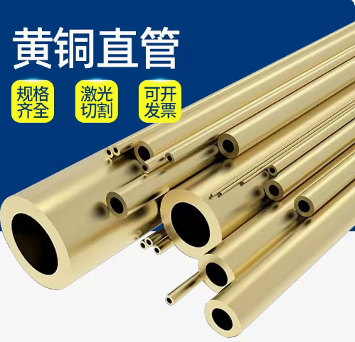
(13) Copper Pipes: [Taobao] https://m.tb.cn/h.UFFvwbm?tk=69bfdNbewLw CZ0001 "H62 Brass Straight Capillary Copper Tube Rigid Environmentally Friendly Hollow Round Tube 2/3/4/5/6/7/8/9/10mm" Click the link to open directly or search on Taobao to open directly.
Body: Buy 4*0.3*half meter (outer diameter 4mm, inner diameter 4-0.2*2=3.6mm)
Body interior: Buy 2.2*0.2*half meter (outer diameter 2.2mm, inner diameter 2.2-0.2*2=1.8mm), internal wiring space = 3.6-1.8mm=1.8mm
Body internal transmission rod: Buy 1.6*0.2*half meter (outer diameter 1.6mm, inner diameter 1.6-0.2*2=1.2mm), which also serves as the sleeve for the petal movable joint, and needs to be cut to the required length yourself.
code.txt
GERBER.rar
Production Materials.rar
Schematic diagram.rar
PDF_【Open Source】Copper Wire Mechanical Flower.zip
Altium_【Open Source】Copper Wire Mechanical Flower.zip
PADS_【Open Source】Copper Wire Mechanical Flower.zip
BOM_【Open Source】Copper Wire Mechanical Flower.xlsx
91133
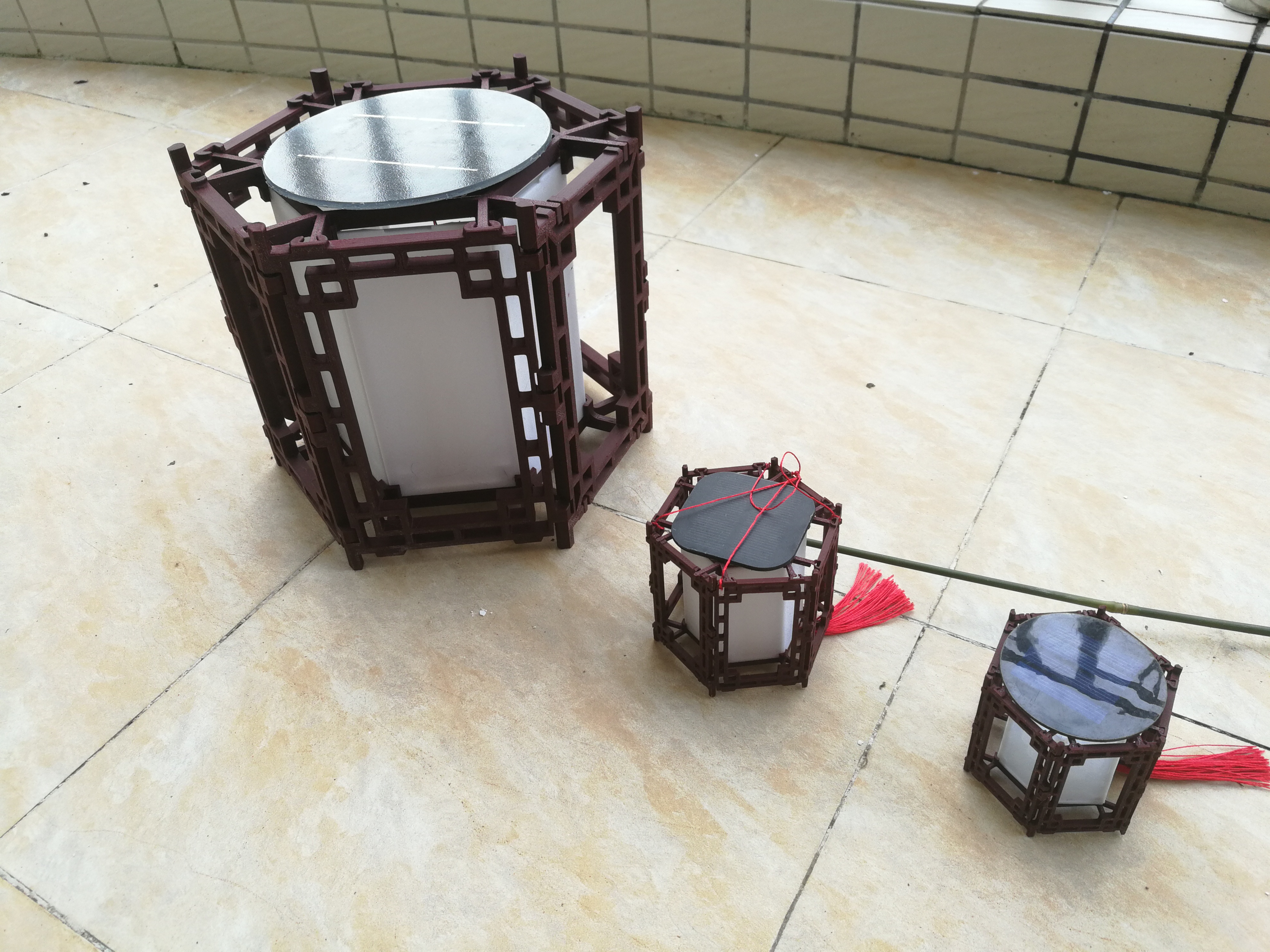
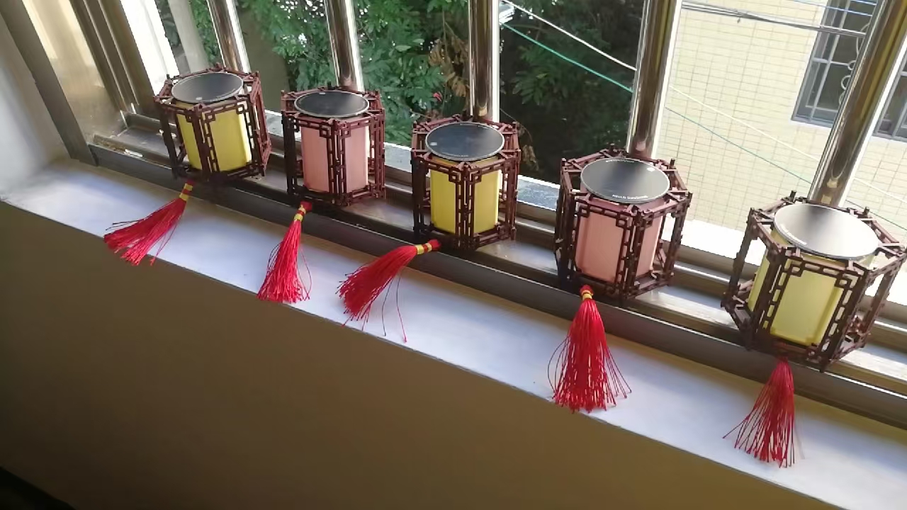
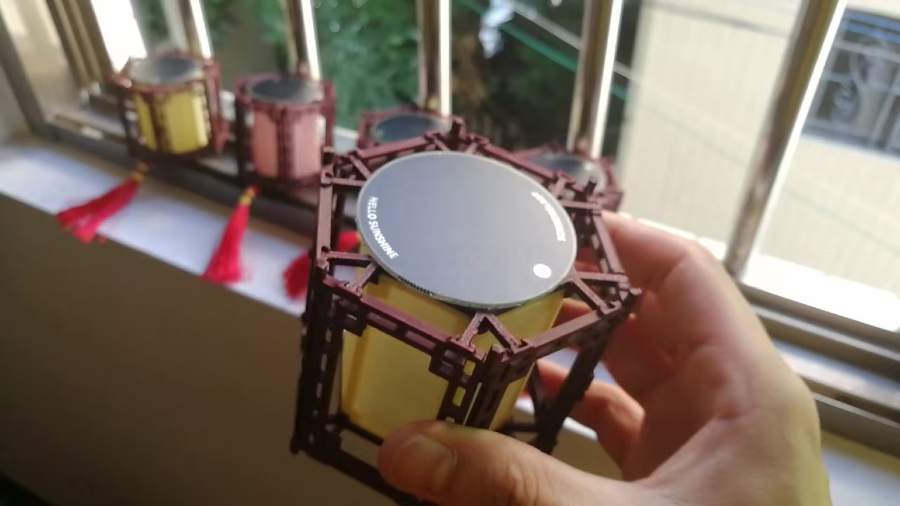
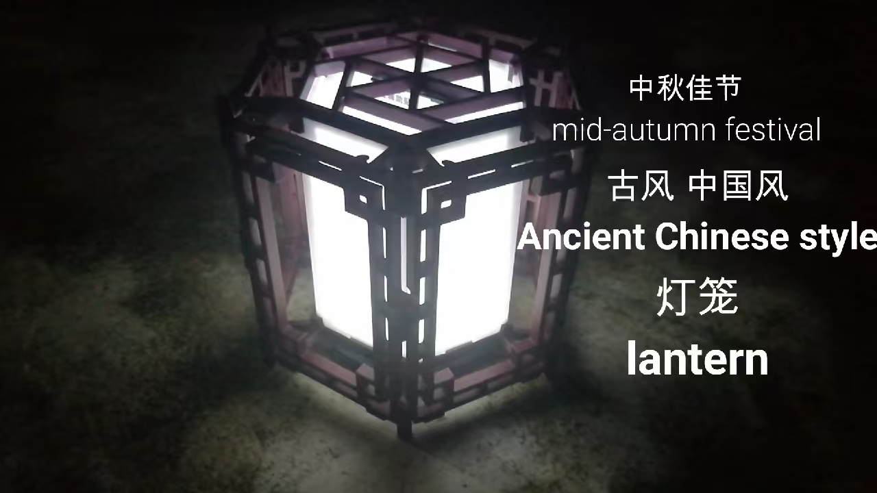
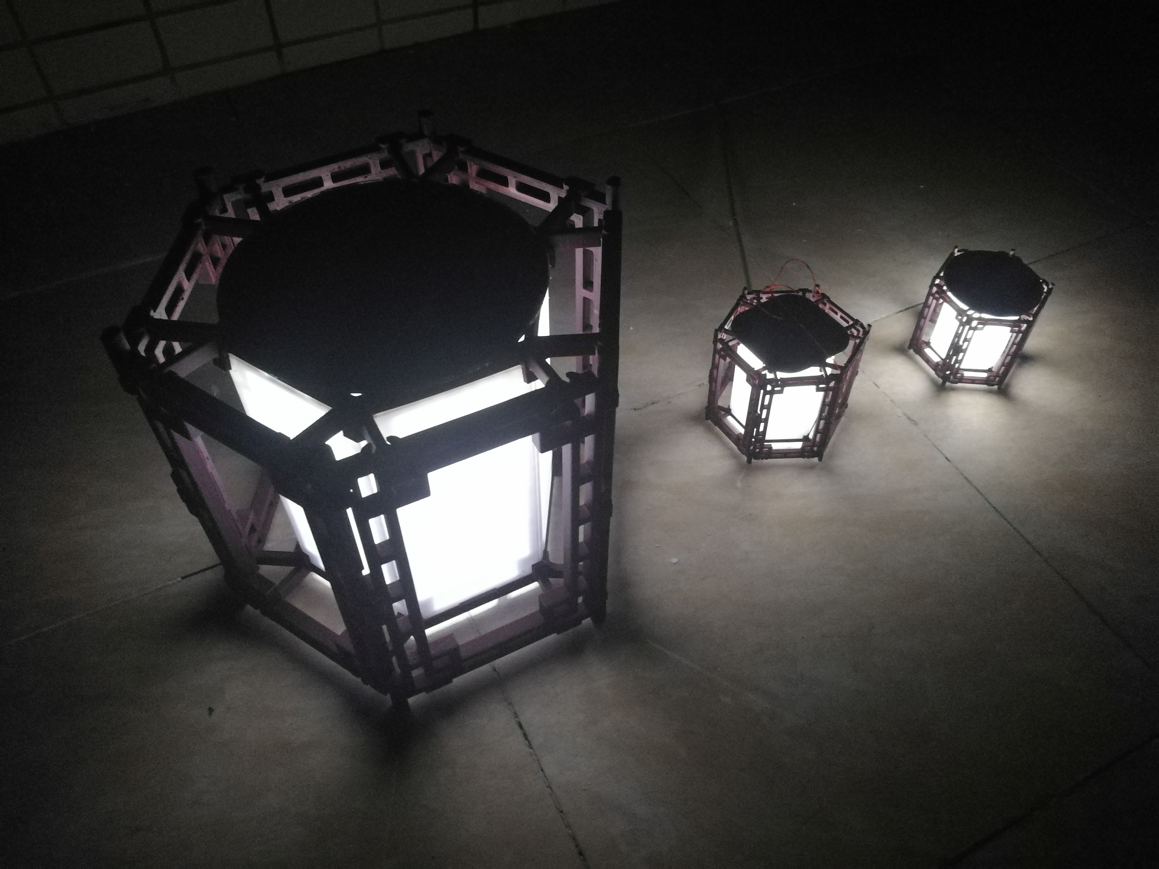
[Open Source] Solar-Powered Traditional Chinese Lantern
This is a traditional Chinese-style lantern designed using a 3D printer. It features a one-piece molded structure, making assembly simple. The single circuit uses an extremely simple solar energy storage circuit, which collects sunlight during the day and automatically lights up at night.
Video Link:
[Homemade Lantern, Chinese Style, Ancient Style, One-Piece Molding, Simple Assembly, Can Be Solar-Powered as a Courtyard Light - Bilibili] https://b23.tv/BT1sKX4
Project Introduction:
This is an ancient style (Chinese style) lantern designed using a 3D printer. It features a one-piece molding structure, simple assembly, and a single-circuit solar energy storage circuit that collects sunlight during the day and automatically lights up at night.
Project Function:
Courtyard or balcony decoration, or a small gift .
Project Parameters :
1. Solar panel, 5VDC (current may vary depending on area and material, but this is not a major issue), size within the top dimension adjusted by the user.
2. LED beads, 6 (1206 package), custom color.
3. Battery life: Varies depending on the solar panel, current-limiting resistor, sunlight conditions, battery capacity, etc.
Principle Analysis (Hardware Description)
: 1. Daytime Energy Storage:
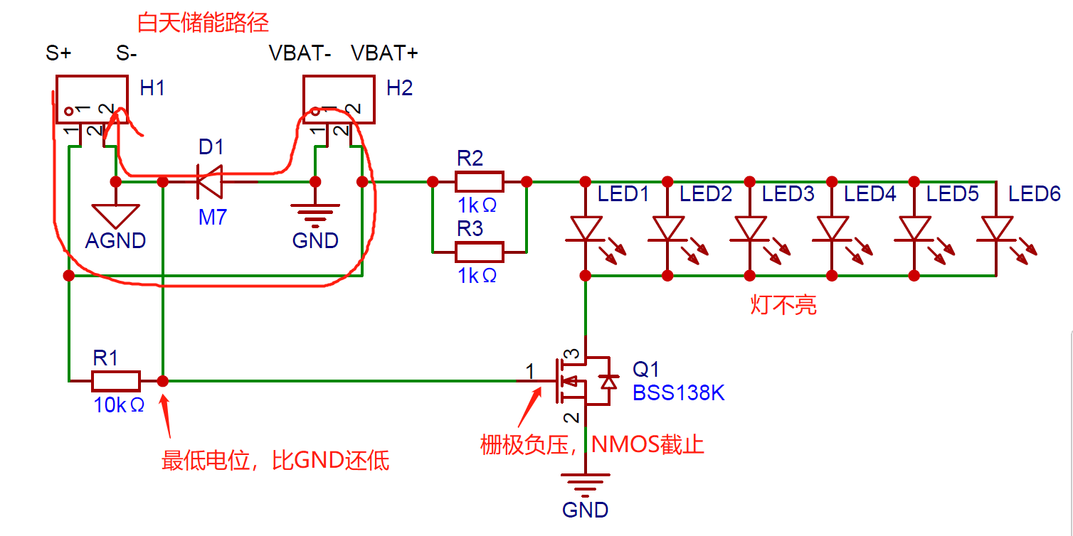
2. Nighttime Lighting:

Note:
Light-colored material should be used for printing the partition to ensure sufficient light transmission.
The lantern size can be cut according to the dimensions of the 3D printer. It can be printed as a single piece to create a smaller lantern, or it can be printed piece by piece and then assembled into a larger lantern.
The larger the battery, the larger the solar panel, the higher the current-limiting resistor, the fewer the LEDs, the longer the sunshine duration, the stronger the sunlight, and the longer the battery life; conversely, the smaller the battery, the stronger the solar panel, the more intense the sunlight, and the longer the battery life. Assembly process:
1. Interlock the ends to form the initial structure.
2. Insert the partition to form the inner cage.
3. Snap the top and bottom together to complete the assembly.

(Image of the actual product)
Ancient style lantern design materials.rar
PDF_【Open Source】Solar-Powered Traditional Chinese Lantern.zip
Altium_【Open Source】Solar-Powered Traditional Chinese Lantern.zip
PADS_【Open Source】Solar-Powered Traditional Chinese Lantern.zip
BOM_【Open Source】Solar-Powered Traditional Chinese Lantern.xlsx
91134
ESP32S3 Visual and Voice Interaction AI Assistant
This project is based on a cloud-based multimodal large model and can realize environmental recognition, visual interaction, voice interaction, and text interaction functions.
AIOT-Phone Multimodal Large Model AI Terminal Device


This is the source code for a multimodal large model AI terminal device
program based on the C language: https://github.com/JasonYANG170/AIOT-Phone
Shell files: https://makerworld.com/zh/models/656401#profileId-583429

(Click here if playback fails) BiliBili
Update Log
V1.1:
1. Corrected the opening position of the LCD touch cable.
2. Improved the circuit design diagram, added categories and comments . 3.
Changed max98357 to QFN package
. 4. Selected a smaller package for the touch cable socket.
V1.2:
1. Insufficient power supply; modified ME6217C33M5G to CJ6109B33M,
consistent package, increased power supply current.
V1.3:
1. Changed LDO to TLV62569DBVR, increased line width, theoretically increasing power supply current to 2A.
PS: When I have time, I'll change the camera and screen to have independent power supplies and rearrange the layout, removing some unimportant components.
Features
: ✅ Supports environmental visual recognition
✅ Supports voice interaction
✅ Supports voice playback
✅ Supports multiple languages ✅ Supports
multimodal large models
✅ Supports LVGL 9.1
✅ Supports touchscreen interaction
✅ Supports screen brightness adjustment.
If you encounter any problems, please submit issues to me.
Project Parameters:
This design uses an OV2640 camera for visual sampling of the environment;
it uses a MAX98357 audio chip for response voice playback;
and it uses an INMP441 omnidirectional microphone for environmental audio sampling.
This project supports MQTT service functionality; you can connect to your MQTT server and use my developed open-source client to control
the services involved in this project. I will provide the `doceker-compose.yml` file on GitHub for easy one-click deployment. Open Source License:
This project follows the CC BY-NC-SA 4.0 open-source license. Please indicate the source and provide a copyright notice when using this program.
This project is for learning and research purposes only; unauthorized commercial profit is strictly prohibited.
If you have better suggestions, PRs are welcome. If you
like this project, please give it a Star ⭐.

Actual Product Images
1
& 2


PDF_ESP32S3 Visual and Voice Interaction AI Assistant.zip
Altium_ESP32S3 Visual and Voice Interaction AI Assistant.zip
PADS_ESP32S3 Visual and Voice Interaction AI Assistant.zip
BOM_ESP32S3 Visual and Voice Interaction AI Assistant.xlsx
91135
SoftXSW-RTL8367S 4-Electrical-1-Optical Switch
The RTL8367S-based 4-electric + 1-optical switch is compact in size and supports seamless switching between primary and backup power supplies.
I. Introduction
This design was inspired by: https://oshwhub.com/kirito/rtl8367-4ge-2sfp_copy
To minimize the board size, this design uses a large number of 0402 resistors and capacitors. If you are not confident in your soldering skills, it is recommended to use a stencil for soldering. It is suggested to find a vendor on Taobao; a small stencil can be obtained for around 20 RMB.
For ease of soldering, all components are placed on the front side of the board – very thoughtful, isn't it?
A: Yes.
II. Power Supply Section
Based on the above design, the power supply section has been modified:
1. A dual-input interface of TYPEC and DC007 has been designed, supporting main and backup power supply. Two SMB-packaged SS54 microcontrollers are used as a MUX to supply power to the subsequent DC-DC circuit. (TYPEC interface: 0.5 RMB; SS54: 0.07 RMB; both are available on Taobao).
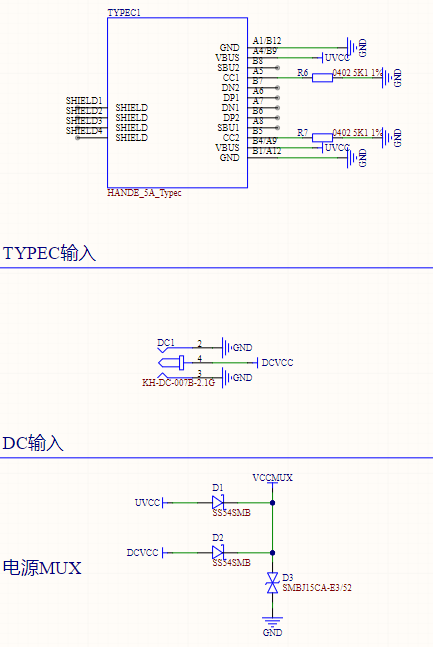
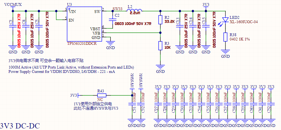
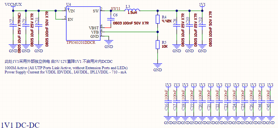
2. The power supply section of the original design was optimized. Due to distrust of the RTL8367S's on-chip DC-DC converter, the required 3V3 and 1V1 voltages are all supplied externally (I love drawing power supplies, and I also love spicy food). The DC-DC power chip was replaced with the inexpensive (0.24 RMB) TPS563201 synchronous Buck controller. This controller supports 4.5-17V input, has a switching frequency of 580kHz, a VFB reference of 0.768V, and a maximum output current of 3A, which is sufficient for this design. To facilitate capacitor parameter adjustment, the input and output filter capacitors in this design use 0805 packages, while the feedback resistors and bootstrap capacitors are 0603 packages. The feedback resistor values are typical values (10K, 33.2K, 4.42K), which can be purchased in most stores. The specific capacitance values of the input and output capacitors are based on TI's webench and personal experience; theoretically, this capacitance is sufficient to support a 3A load.

Due to space limitations, the power supply layout in this design is not optimal. I have tried my best to optimize the power supply layout. If you have a better layout recommendation, you can modify this design accordingly.
III. Interface Section
: Due to limited board space, it is difficult to fit a traditional network transformer. Therefore, other methods must be used. This design directly uses the integrated network transformer's network port (HR911130A), but this port is relatively expensive. If cost is a concern, you can consider the solution of TVS + DC blocking capacitor + common mode inductor + autotransformer.
IV. Pin Configuration:
PIN45-PIN56 are disabled and connected to a 1K pull-down resistor. For PIN51-56, the chip datasheet clearly states "[This pin must be pulled low with a 1K ohm resistor when not used.
]". PIN45-50 are not explicitly required by the datasheet, so they are also treated as 1K pull-down resistors.

PIN13, according to the chip datasheet, is connected to a 2.49K 1% error resistor.
PIN60: EN_SWR. According to the chip datasheet,
[Pull Up: Enable Internal Switching Regulator.
Pull Down: Disable Internal Switching Regulator.
This pin must be pulled high or low via an external 1k ohm resistor during normal operation.]
Here, we disable the chip's internal switching circuit by pulling it down to GND via a 1k ohm resistor.
PIN70: EEPROM Mode Selection. Select according to the EEPROM capacity.
Pull Up: EEPROM 24Cxx Size greater than 16Kbits (24C32-24C256).
Pull Down: EEPROM 24Cxx Size less than or equal to 16Kbit (24C02-24C16).
Note: This pin must be kept floating, or pulled high or low via an external 4.7k ohm resistor upon power on or reset.
This design uses 24C64, therefore a pull-up is used.
PIN73: EN_PWRLIGHT. When the RTL8367S powers on, all network port LEDs will blink once. You can pull EN_PWRLIGHT low to disable this blinking process. Here, we choose to enable blinking to easily confirm whether the chip has successfully loaded the firmware.
Connect to a 4.7K pull-up.
PIN74: Enable SPI FLASH Interface. Controls whether to enable SPI FLASH.
Pull Up: Enable FLASH interface
Pull Down: Disable FLASH interface
This design uses IIC FLASH, so connect to a 4.7K pull-down to disable the SPI FLASH interface.
PIN75: Disable Embedded 8051. Controls whether to enable the internal 8051.
Pull Up: Disable embedded 8051
Pull Down: Enable embedded 8051
This design requires firmware loading, so connect to a 4.7K pull-up to enable the internal 8051.
PIN76: Disable EEPROM/FLASH Autoload. Controls whether to automatically load firmware.
Pull Up: Disable EEPROM/FLASH autoload
Pull Down: Enable EEPROM/FLASH autoload
This design requires firmware loading, therefore the 4.7K pull-down pin allows automatic firmware loading.
PIN79: Enable Embedded PHY. Controls whether to enable the chip's internal embedded PHY.
Pull Up: Disable EEPROM/FLASH autoload
Pull Down: Enable EEPROM/FLASH autoload
We naturally want to directly use the chip's integrated PHY, as the chip is directly connected to the grid transformer, therefore the 4.7K pull-up pin is used.
PIN81: EEPROM SMI/MII Management Interface Selection. Used to select the management interface. Here, we do not need management and will not configure it.
V. 3V3 and 1V1 Power Supply Test
Without a grounding pin, a grounding clip was used for testing. The ripple was 40mV, which is acceptable.

VI. Firmware Flashing
This design uses ST's M24C64, an 8KB EEPROM.
Please ensure that after writing the firmware, you read the firmware multiple times to ensure the read content is correct. If there are problems, please try changing the chip type, such as selecting another model like M24C32 in the programming software.
VII. Speed Test


PDF_SoftXSW-RTL8367S 4 Electrical 1 Optical Switch.zip
Altium_SoftXSW-RTL8367S 4 Electrical 1 Optical Switch.zip
PADS_SoftXSW-RTL8367S 4 Electrical 1 Optical Switch.zip
BOM_SoftXSW-RTL8367S 4 Electrical 1 Optical Switch.xlsx
91136
SoftXONU-2.5G Fiber Optic Transceiver
A 2.5G mini SFP transceiver that is exquisite, compact, and inexpensive.
November 10, 2024 Update Log: Added test screenshots for the cat stick.
I. Preface
- 1. You shall bear all security and legal risks arising from replicating, iterating, or modifying this design.
- 1. You shall bear all security and legal risks arising from
replicating, iterating, or modifying this design. - 1. You shall bear all security and legal risks arising from replicating, iterating, or modifying this design.
You may not use this design for commercial purposes!
You may not use this design for commercial purposes!
You may not use this design for commercial purposes!
0. The price of 2.5G SFP transceivers on the market is outrageously high, with some transceivers even costing more than a 4x2.5G+2x10G switch. SFP transceivers on the market are too bulky and unsuitable for home users with small weak current boxes.
1. This design uses the RTL8221B chip to implement a 2.5G fiber optic transceiver. The SFP rate is fixed at 2.5G (details explained below), and the network port supports 10M/100M/1000M/2.5G speeds.
2. This design uses a four-layer board design. The board dimensions are 20mm x 65.2mm x 1.6mm, and the matching housing dimensions are 28mm x 69.2mm x 21.4mm. Most materials can be purchased with coupons of 16-15 yuan, and even without coupons, the overall material cost can be controlled within 25 yuan.
II. My Requirements
1. Overall Requirements: The initial purpose of this design is simply to use fiber optic cable as the uplink for the home access point (AP). This allows me to place the AP in a central location in my home and connect it to the core switch in the internet access area of the server rack via fiber optic cable. I'm using the AX5400PRO as the access point (AP). This AP has a 2.5G Ethernet port. To maximize wireless bandwidth, a fiber optic transceiver that supports 2.5G, is easy to power (preferably USB), compact, and doesn't use inferior components is crucial.
2. Power Requirements:
Compact input interface (this design uses a 6-pin Type-C interface, which is easy to solder and inexpensive).
High conversion efficiency (both 0.95V and 3.3V power supplies use DC-DC converters, not LDOs), low heat generation (using synchronous Buck converters).
Chip output capability must meet the requirements of the chip and SFP module.
Therefore, this design uses my favorite DC-DC chip, the TPS563201, which is inexpensive (0.24/chip), has a high switching frequency, and a low failure rate.
3. Ethernet Port Requirements:
At least two indicator lights; wiring sequence must meet chip design requirements (this design uses the RTL8221B, which supports MDI SWAP, so this is not a concern).
The Ethernet port price cannot be too high, and the network transformer must be sufficiently compact.
In summary, this design uses a flat network transformer (G2425S) + network port (HC-WK88-H16-DB) (remember to use the 16-15 coupon from the online store when purchasing, which is practically free).
4. Layout Requirements:
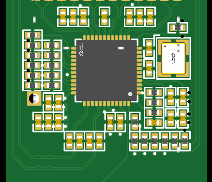
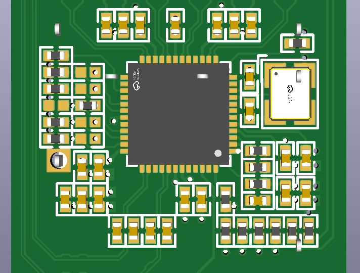
This design aims for minimal size. The SFP, network port, DC-DC converter, main chip, network transformer, and a large number of configuration resistors and filter capacitors need to be squeezed together, so the layout method needs to be prioritized. This design ultimately adopts a layout where only the RJ45 and SFP are placed on the front, and all other components are placed on the back.
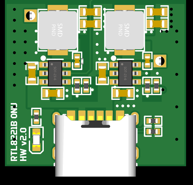
Front view:
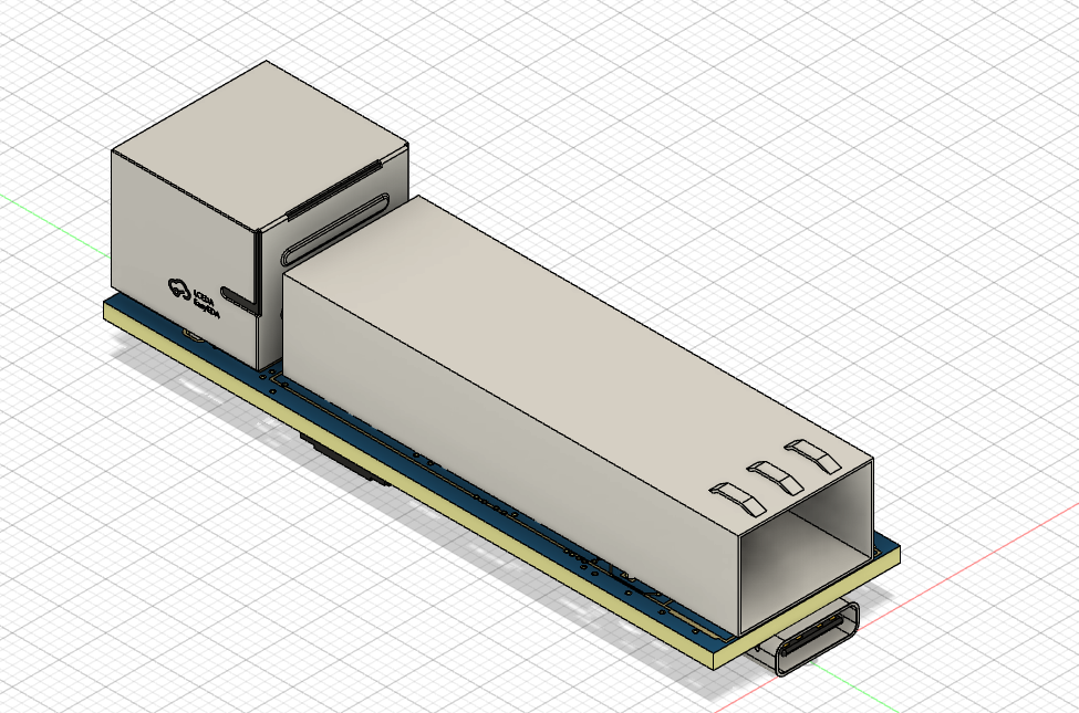
Back view:

This layout method can minimize the PCB size. However, because the TYPEC female connector and SFP cage are on top of each other, even with a board thickness of 1.6mm, the outer sheath of the TYPEC cable will interfere with the SFP module. Therefore, when using this design, it is necessary to scrape off part of the outer sheath of the TYPEC interface with a knife, or use a 10mm extended TYPEC cable (available on Taobao).
III.
Power Supply Design:
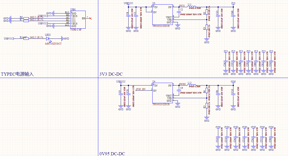
A Type-C female connector is used as the power input interface. 5.1K pull-down resistors are configured on the CC lines to support the CC wires.
Using TI's webench, the DC-DC circuit is built and laid out, resulting in the following design.
Note that the MLCC capacitor has bias characteristics. The pads for the DC-DC filter capacitor section in this design are designed to be 0603, but 0805 capacitors can actually be soldered. If you require a higher input voltage, you can solder 0805 capacitors yourself.
RTL8221 Main Chip Design:
The crystal oscillator and start-up capacitor are placed close to the main chip.
Filter capacitors and configuration resistors are placed as close to the main chip as possible (in the case of small size and single-sided layout, it is impossible to have filter capacitors near every pin).
Coupling capacitors are placed close to the main chip (due to space constraints, HSO and HSI coupling capacitors are placed close to the main chip).
Network Transformer and Ethernet Port Design:

The RTL8221's LED and PHYAD share pins. For design flexibility, the LED and PHYAD are configured in flexible mode. You can solder the corresponding resistors according to your needs. The specific soldering relationships are as follows:

Generally, solder according to the red text (i.e., do not solder any marked NC). The final soldering effect should look like this:

4. SFP cage pin modification: This design has deleted most of the SFP cage pins (only 1, 8, 9, 10, 16, and 17 are retained, and the stability is not a problem in actual testing). Before soldering the SFP cage, be sure to trim the pins.
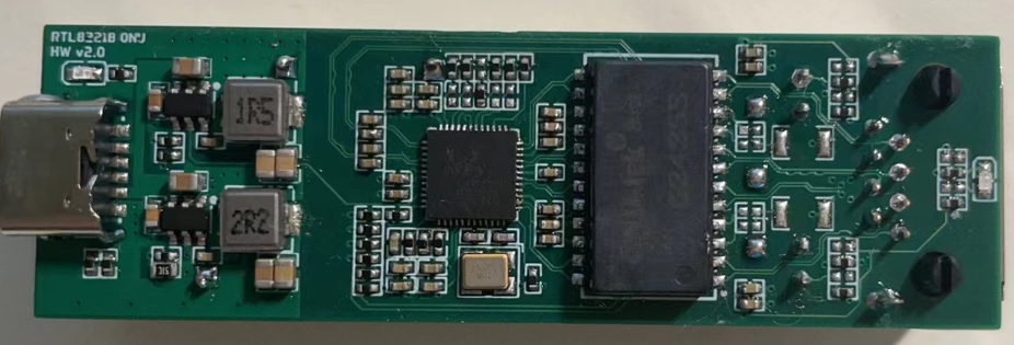
IV. Soldering
This design uses a large number of 0402 resistors and capacitors. It is recommended to use solder paste stencil + heating table for soldering.
The pads of RTL8221B have been elongated. If there is solder bridging after soldering on the heating table, use a pointed soldering iron + flux to smooth it out.
The soldering effect is as follows:
V. Testing
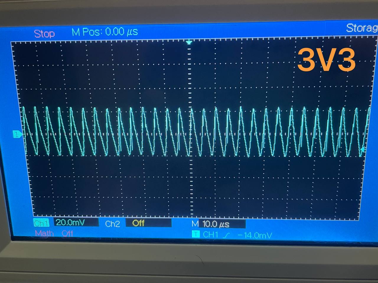
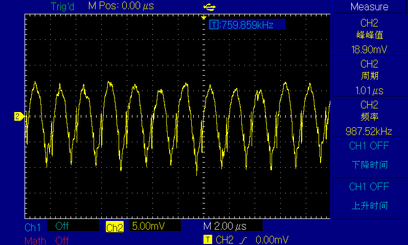
1. Test whether the voltage and ripple of the DCDC section meet the requirements. After actual testing, both voltage outputs are normal, the ripple also meets the expectations, and the chip switching frequency is not much different from the description in the manual.
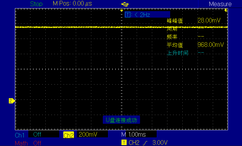
3.3V voltage and ripple test screenshot:
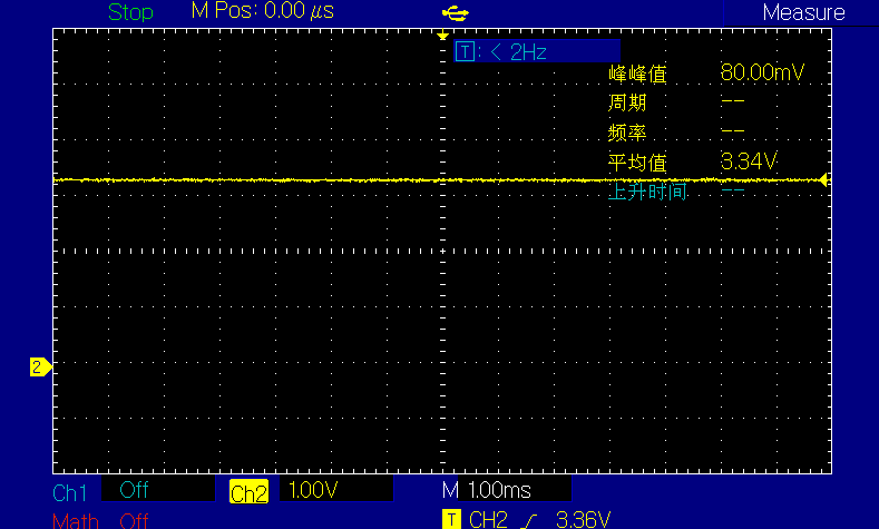

0.95V voltage and ripple test screenshot:
2. RJ45 part test:
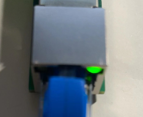
Connect a 2.5G device and check the link negotiation status. At this time, the green LED on the right side of the network port lights up.

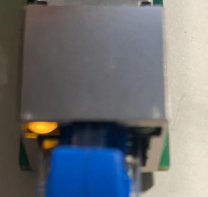
Connect a 1G device and check the link negotiation status. At this time, the yellow LED on the left side of the network port lights up.

Connect a 100M device and check the link negotiation status. At this time, the LED at the bottom of the network port lights up.


3. SFP part test
: A certain H brand 2.5G 1310nm 2km optical module was used for testing.
The test peer device was an RTL8372N switch.
The SFP worked normally in the test (this design does not have a reserved SFP status indicator light
. You can modify this design yourself). Why did the transceiver not work normally when I inserted a 1G optical module? Because the default SGMII interface type of the RTL8221B is the HiSGMII interface, with a rate of 2.5G. You can add an external microcontroller and use the MDIO interface to change the SGMII interface type to the ordinary SGMII.
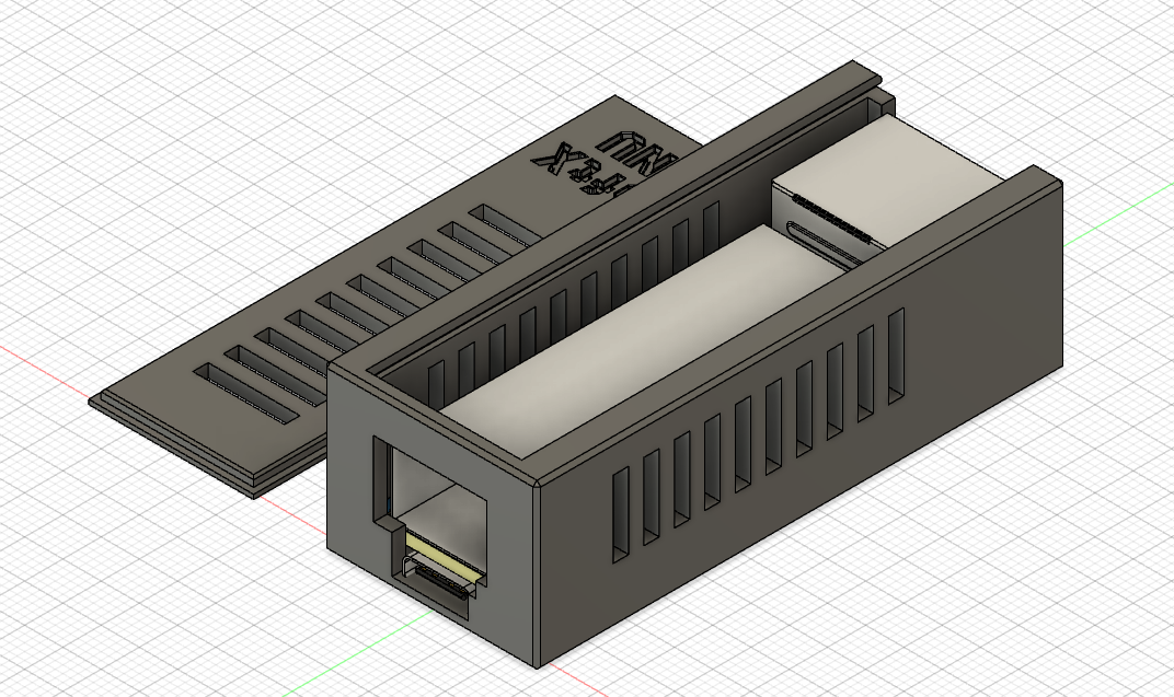
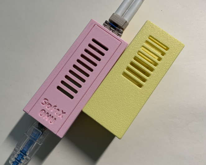
VI. Shell Printing
You can directly print the shell shown in the design appendix, or you can design your own shell.
It is recommended to use high-temperature resistant materials for printing.
VII. Pressure Testing
1. Ping Test

2. DPerf Streaming Test
Experimental Environment:
Physical Machine Configuration
| Key | Value |
| --- | --- |
| Host | M920X |
| OS | PVE 7.1 |
| CPU | G5420 |
| MEM | 2xDDR4-4G@3200MHz |
| DISK | MICRON 2200 1TB |
| NIC | SP310 |
VM Configuration
| Key | Value |
| --- | --- |
| OS | Debian 11 |
| CPU | 2vCPU |
| MEM | 3G |
| DISK | 50G |
| NIC | SP310(1Port) |
| Hugepage | 2M*1024 |
| DPDK Version | 23.11.2(LTS) |
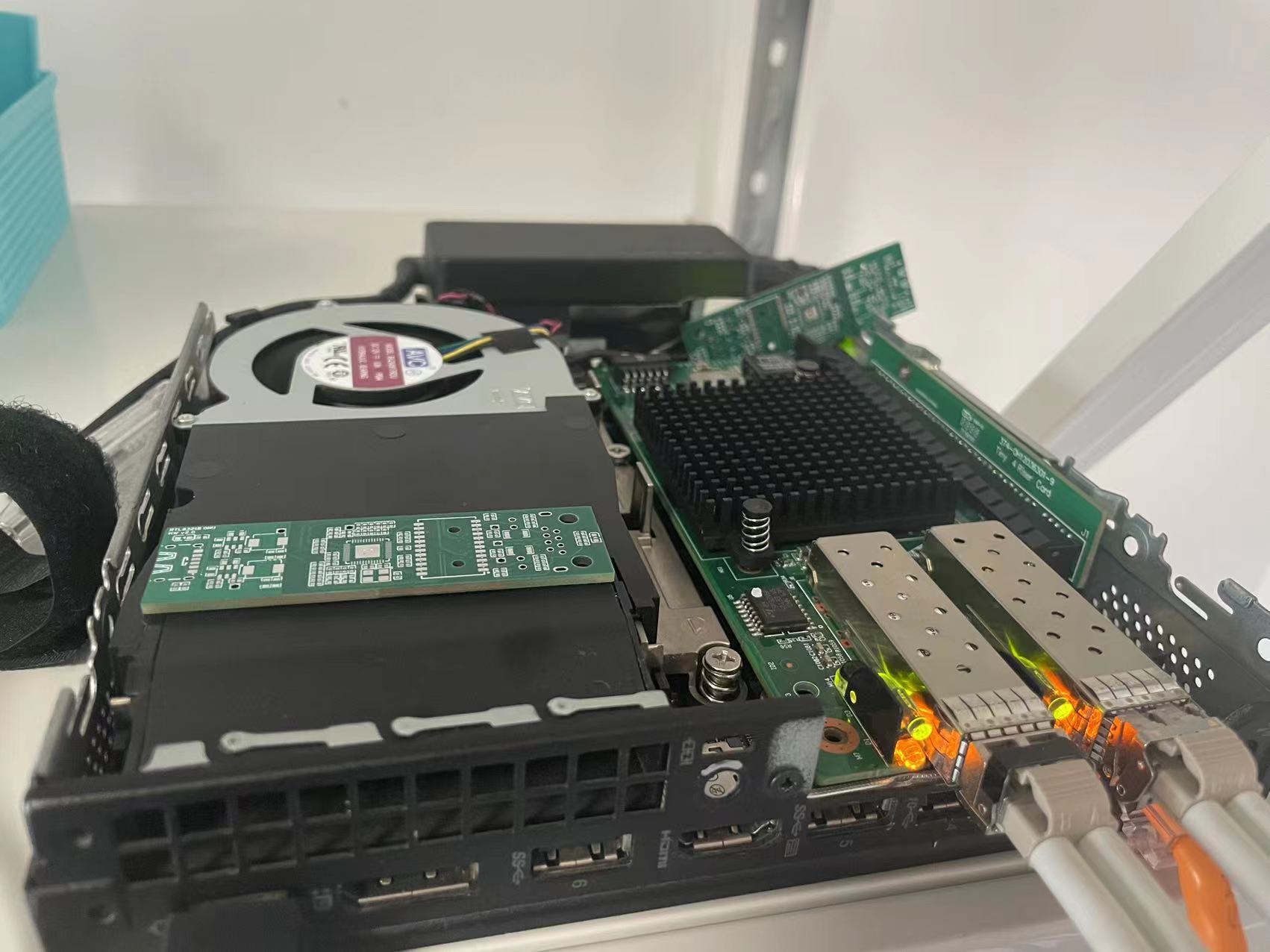
| DPerf Version | 1.8.0-dev The physical
machine is an M920X with an SP310 network card. The two ports of the network card are directly connected to two VMs (this can be achieved by enabling PCIe ACS override).

Since the CPU does not support 1GB Hugepages, 1024 2MB Hugepages are allocated to each VM.

The network card is mounted to the DPDK protocol stack using the uio_pci_generic driver.

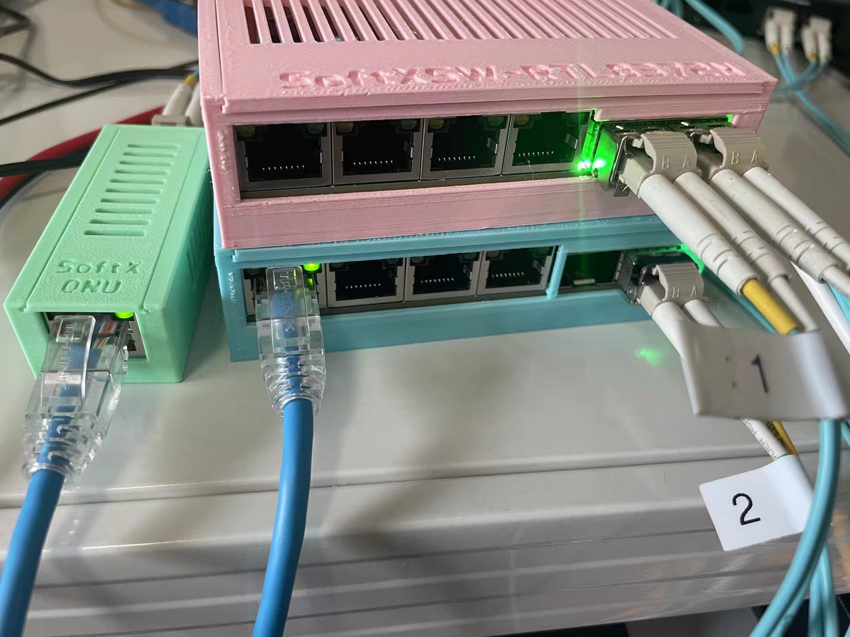
The test machines are named VM1 and VM2, and the system connection is shown in the figure.
VM1_10G <--10G--> SW1 <--2.5G RJ45--> SoftXONU <--2.5G SFP--> SW2 <--10G--> VM2_10G.
A unidirectional bandwidth test was performed on SoftXONU, yielding the following results (only the RX signals on both sides are considered; TX is meaningless):
RJ45 to SFP, speed approximately 2.459Gbps (1500 large packets);

SFP to RJ45, speed approximately 2.459Gbps (1500 large packets).
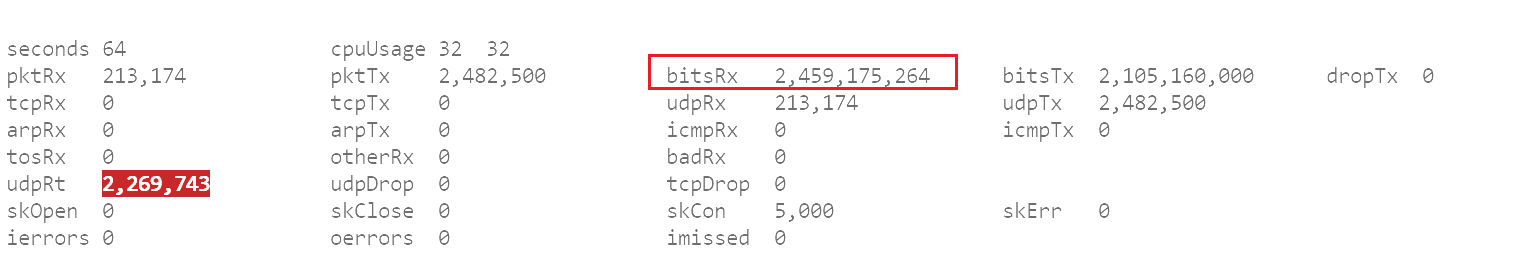
We can assume that SoftXONU can fully utilize the unidirectional bandwidth.
Bidirectional streaming was performed on the SoftXONU, and the following test results were obtained (full CPU usage on the client side is normal; the inability to fully utilize the bidirectional 2.5G bandwidth is not a bottleneck on the client side).
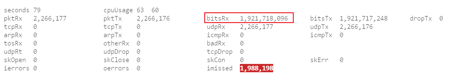
SFP to RJ45: speed approximately 1.921Gbps (64K small packets).
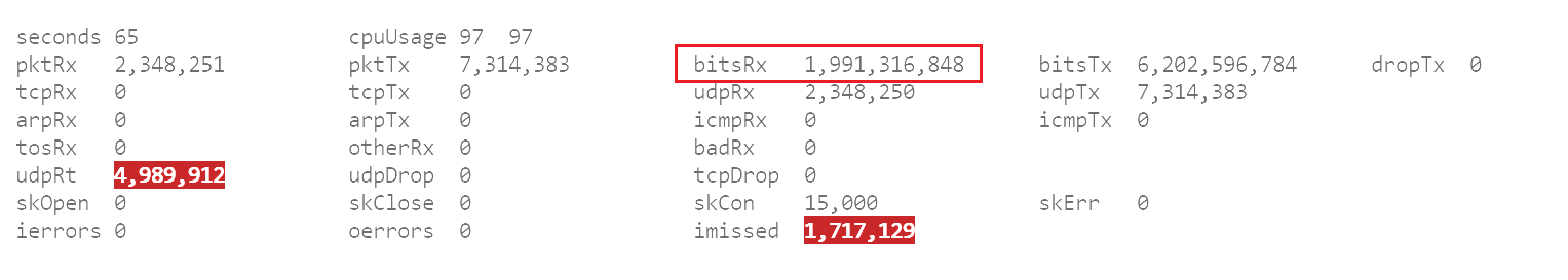
RJ45 to SFP: speed approximately 1.991Gbps (64K small packets).
The conclusion is that the SoftXONU cannot fully utilize the bidirectional bandwidth. This is likely because the SoftXONU uses gigabit network ports and adapters, which cannot meet the high bandwidth requirements of fully utilizing the bidirectional 2.5G bandwidth (2.5GBASE-T uses PAM16 code with a symbol rate of 200 Mega Baud, compared to 1000GBASE-T's PAM5 code of 125 Mega Baud; 2.5GBASE-T has higher requirements for network adapters and ports).
Compact 2.5G network adapters are hard to find on the market. If you have a more suitable 2.5G network adapter recommendation, please leave a message or send a private message!
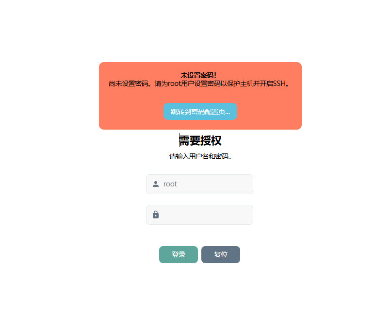
Screenshots of the Cat Stick test are as follows:
VIII. Design Demonstration

SoftXONU casing.step
Gerber PCB Design Files - SoftXONU - V2.0.zip
PDF_SoftXONU-2.5G Fiber Optic Transceiver.zip
Altium_SoftXONU-2.5G Fiber Optic Transceiver.zip
PADS_SoftXONU-2.5G Fiber Optic Transceiver.zip
BOM_SoftXONU-2.5G Fiber Optic Transceiver.xlsx
91137
CSPS-ATX12VO Smart Power Supply
The CSPS power supply intelligent power engineering project, including the power supply board, core board, and hard drive power supply board, is open-sourced for those who need it. The power supply board was inspired by the CSPS power supply board open-sourced by the user wuyu, and has been ported to the existing power engineering project. Some circuits have been modified to meet specific requirements.
CSPS Smart Power Supply
Project References:
【wuyu无语】Huawei 460W_CSPS Power Supply_esp8266 Smart (?) Power Supply Board - JLCPCB EDA Open Source Hardware Platform (oshwhub.com)
ATX Power Plan - JLCPCB EDA Open Source Hardware Platform (oshwhub.com)
ATX Power Plan Interface Adapter - JLCPCB EDA Open Source Hardware Platform (oshwhub.com)
GitHub - hitsword/csps_esphome: CSPS Power Supply PMBUS For ESPHome
GitHub - KCORES/KCORES-CSPS-to-ATX-Converter: Super ATX Power!
ESP8266 Pin Usage Notes and Recommendations - Zhihu (zhihu.com)
I. Project Overview
The project includes:
Power interface board (ATX3.0)
Core board (ATX3.0)
II. Detailed Introduction
1. Power Interface Board (ATX3.0)
It adopts a Noguchi 64P input, 4 XT60PW-F and MX3.0-10P (ATX3.0 standard) outputs.
The DC-DC main controller uses TPS563201DDCR, SMF3.3A (or ZMM3V3) for overvoltage protection
, 2N7002 for I2C level conversion, and
ESP8266 (ESP-12F or... ) After the ESP-12E is linked with Home Assistant, it can be remotely started and its voltage, current, power, efficiency, and
other data can be read in real time. More power data can be read through custom register addresses.
Compatible power supplies: EPW750-12A, PS-2751-7H; other power supplies have not yet been tested.
Due to size and cost limitations, the recommended total power of this power board is no more than 600W.
A copper busbar soldering position (6mm (width) * 50mm (length)) has been reserved.
A forced output shutdown function has been added, which requires Home Assistant. Firmware must be flashed to force IO2 to go high; otherwise, the physical switch will not work. See Figure
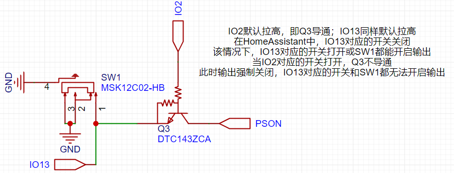
2 for details. Core Board (ATX3.0):
The main circuits of the core board have been windowed.
One PW22ASAB is used for both 5V and 3.3V outputs, and one ZXDN10 is used for 5VSB.
The main control chip is either WT7510 or TPS3510.
III. Postscript:
Because everyone's development environment is different, tutorials on Home Assistant and ESPHOME are not provided. Related tutorials can be found on Bilibili or other platforms.
For firmware flashing of the ESP8266, please prepare a jumper cap and a USB-to-serial adapter module. The silkscreened TX and RX should correspond to the TX and RX of the programmer (the order does not need to be swapped).
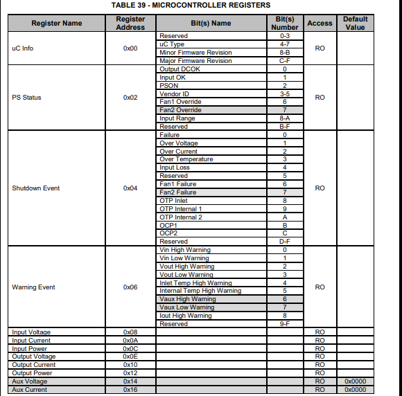
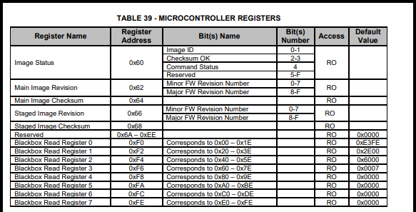
IV. PMBUS I2C Address Reference (PS-2751-7H)

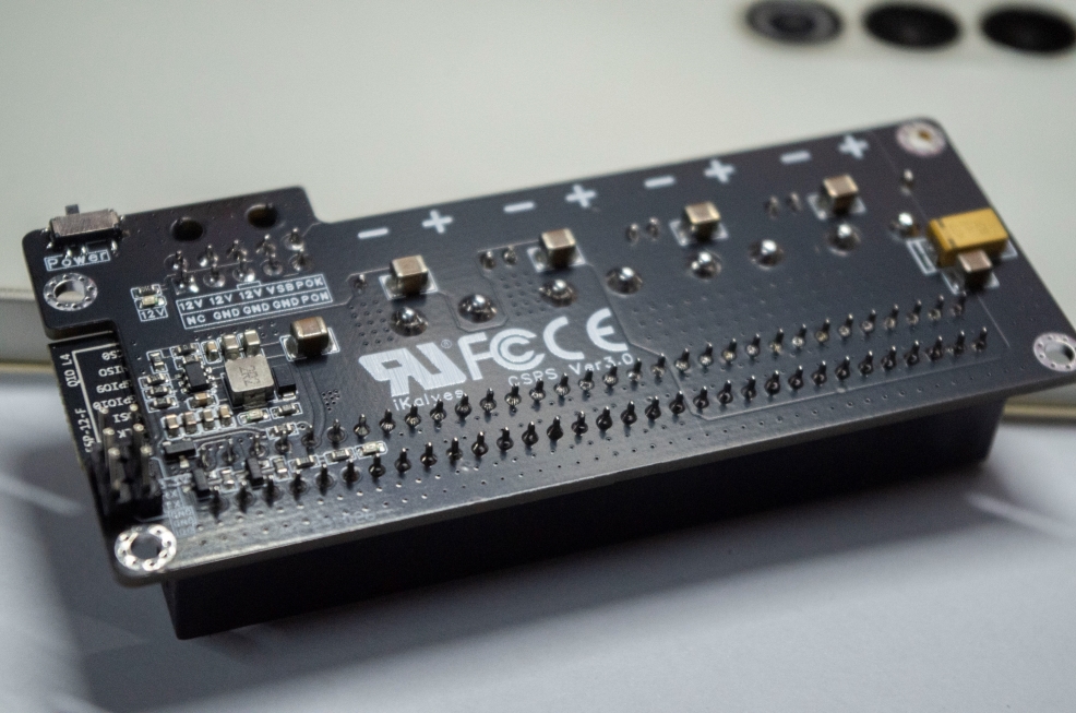
V. Reference Images


flash_download_tool_3.9.5_0.zip
esp-12f_product_specification_zh_v1.0_2.pdf
csps_esphome_code (Ver3.0).zip
csps-power-Ver3.0 firmware.bin
Huawei-EPW750-12A-datasheet.pdf
PS-2751-7H-LF Lite-On 750W Platinum Power Supply Datasheet (VDpdf)
NAK12S20(PW22AS)(1).pdf
Power Supply Compartment Model (SFX Bezel).step
BOM_Power Interface Board (ATX3.0) 2024-09-26.xlsx
PDF_CSPS-ATX12VO Smart Power Supply.zip
Altium_CSPS-ATX12VO Smart Power Supply.zip
PADS_CSPS-ATX12VO Smart Power Supply.zip
BOM_CSPS-ATX12VO Smart Power Supply.xlsx
91139
electronic


 京公网安备 11010802033920号

 C630C109KDR5TA


