Risk Warning:
This project involves 220V high-voltage electricity, and there are serious electrical risks during use.
Please ensure you have professional electrical skills or seek support from a professional electrician for installation and operation.
You are solely responsible for any electrical risks, and I am not liable for any loss or damage caused by using this project.
Project Background:
This is my first self-taught project since getting into PCB design. Lacking any software or hardware background, I relied purely on blind confidence, so it took me more than six months to complete intermittently. I estimate it will take another six months to reach my ideal form.
Replicating
the Initial Non-Metering Version Product Design: The initial non-metering version design was a replica of the smart socket by "520world". Click to jump to
the second updated metering version hardware design, which referenced the magnetic latching metering socket by "oldfox". Click to jump to the BL0937 chip
update:
2024.9.13
Last week, based on the BL0937 documentation, I updated the power supply and metering chip routing. After testing today, both voltage and current are displayed stably; and the YAML file and calibration values have been updated.
For those interested, you can try to replicate this.
To-do:
Since ESPHome displays real-time power consumption as xxx W, I'm currently testing how HA can effectively calculate cumulative power consumption by day.
With the hardware design successful, I plan to update the chip to ESP32 and modify a metering socket using the ESP-IDF protocol. This way, it won't be limited to HA, allowing Apple ecosystem users to use it out of the box. Wishing myself good luck with my coding studies!
2024.9.7
Special note: The metering function is not calibrated. Other functions are normal and usable. However, adjusting the metering function may affect the circuit design. If you don't mind, you can try replicating it. I'm posting it now, hoping some experts can help guide me!
2024.7
I wanted to replicate a metering socket, but coincidentally, two classmates used two different shell molds on the market. After using 520world's PCB design, converting it to a metering version requires using oldfox's metering circuitry. I had to assemble it manually.
Fortunately, after half a year of learning and exploration, and wasting countless PCBs, I've finally grasped the basic principles of PCB design. After two mistakes, I finally succeeded in replicating the metering circuitry onto the original circuitry in terms of hardware. I also modified the 8266 chip layout and power supply location (I had indeed blown one up before). The first version of

the 2024.2
hardware is a replica, so there's no scenario for sharing it.
For software, I used ESPHOME, which is better than Tasmota because it makes it easier for beginners to learn the code.
Final Form (Unrealized, Ideal Goal):
My ideal form is one that can directly connect to an iPhone and display metering correctly. Therefore, adjustments are still needed:
Matter protocol support (the chip will likely be upgraded to ESP32
, and the code might be changed to Espressif's Rain chip);
and I'm currently learning about metering calibration, as I haven't yet grasped the underlying principles. Any
guidance from experts would be greatly appreciated.
Version Update
2024.5.1 V0.1.0: Completed the replication of the standard version. The code was compiled using ESPHome and can directly connect to Home Assistant. Of course, if you don't use HA, you can also control it via a web browser (though I doubt anyone would be that bored).
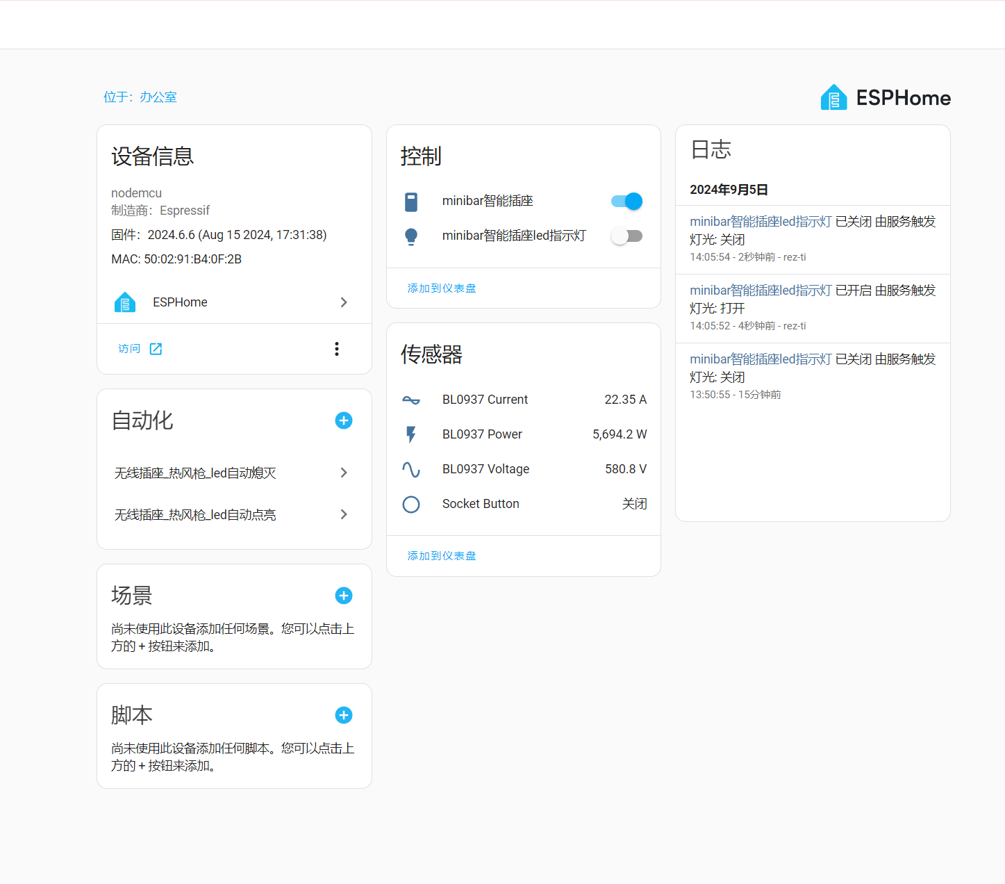
2024.8.30 V0.2.0: Completed the hardware replication of the metering socket and optimized the circuit design; the updated ESPHome code can display "voltage," "current," and "power" values, but the calibration process is still not fully understood. I'm sharing this now in the hopes of receiving guidance from experts.
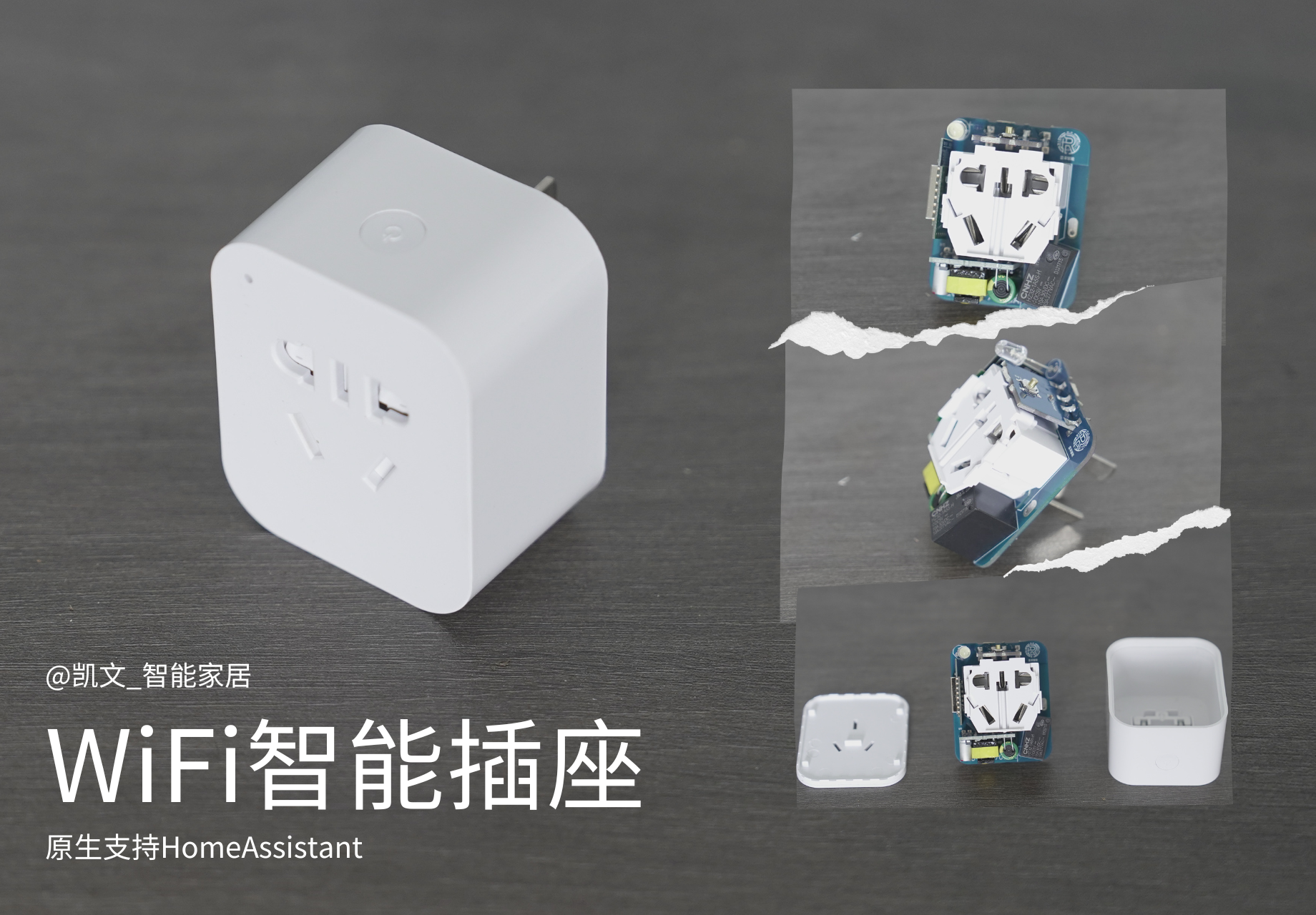
Finished Product Display
Cost Estimate and Purchase Suggestions
Cost Estimate:
Around 20 RMB, depending on your PCB cost fluctuations. Main Components Required for Purchase:
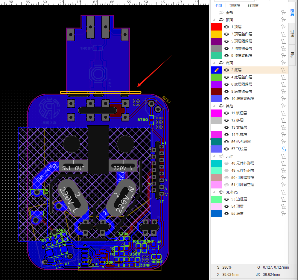
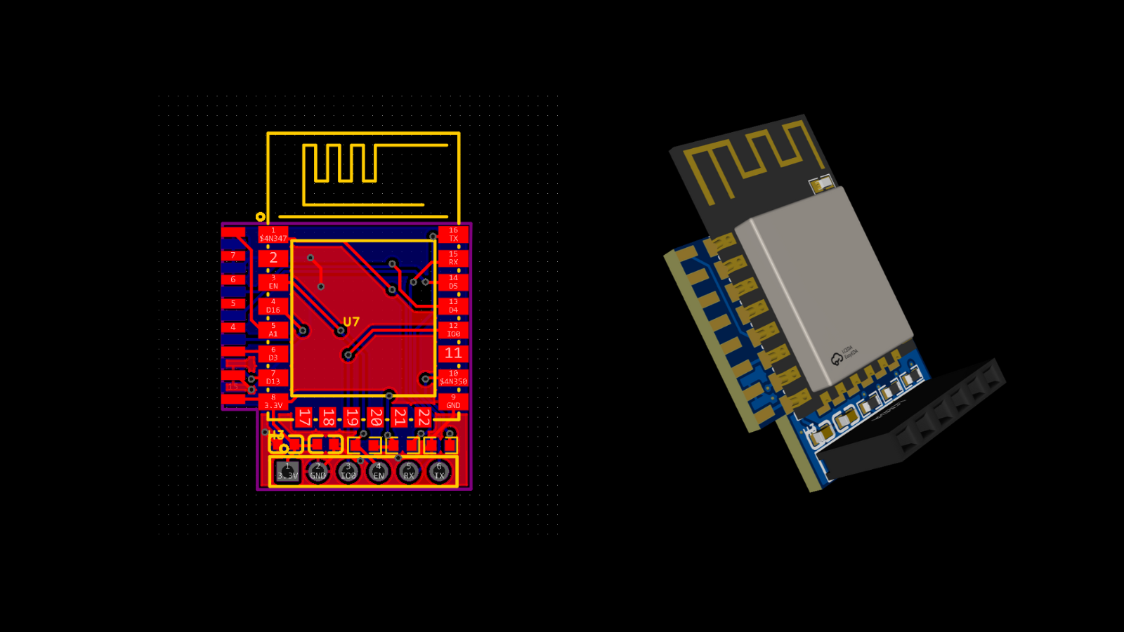
Component Name Reference Price Purchase Channel Link Universal Mold Shell Set 5.5 Alibaba Click to Jump AC-DC Power Module 3.9 Taobao (Shenzhen Youxin Electronics) Search in Store Small Relay 1.5 Taobao (Recommended: My Store - Source Factory) Click to Jump BL0937 Metering Chip 0.89 Taobao (Hengxin Kechuang Electronics) Click to Jump PCB Circuit Boards 2 Pieces / Jialichuang / ESP8266 chip 5.2 Alibaba ( click to jump) capacitors, resistors, and other accessories / Taobao (recommended Shenzhen Youxin Electronics) search in the store. The prices above do not include shipping. Note that Alibaba and other stores require separate shipping fees, so try to buy everything in one place. I've encountered some pitfalls, especially note: there are two types of socket molds, so be careful not to buy the wrong one. For AC-DC, you can buy 5V 700mA. I've been using this without any problems, but it seems that the lowest price on the market is more than 2 yuan. If you have better cost-effective recommendations, please share. Relays: there are many relay models, so be sure to pay attention to the model. I'm using a 5V 4-pin normally open ESP8266 chip. Buy the best-selling ones on Alibaba. They work without problems, but if you want to use the deep sleep function, you need to optimize the circuit. You can find detailed hardware design/PCB design instructions online . The PCB design consists of two parts: the smart socket body and the ESP8266 chip circuit . The smart socket body shouldn't be anything special; you can just follow the instructions for board design. I've added capacitor and resistor values to my silkscreen for easier soldering. They're all 0603 packages, which are easy to solder. The original author added the design shown in the image below to the PCB design; you can cut it open with a blade after receiving it. This PCB can accommodate a 1.6mm thick ESP8266 chip circuit. I modified the design, increasing the length and placing all the resistors on one side for easier soldering. Note that this board needs to be 1.0mm thick.
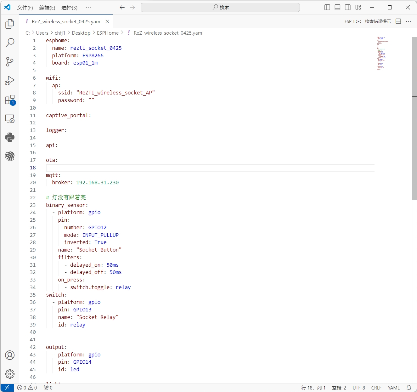
The software design/code reference
ESPHome's code (more accurately, the YAML configuration file) is very suitable for beginners. I'm sharing my source code and bin file with everyone;
the source code is for beginners to understand ESPHome's configuration logic
, and the bin file can be used directly for flashing. After flashing, refer to the usage tutorial.
Note that
the metering is currently uncalibrated; I'm still exploring it. However, it works fine as a normal smart switch. I'll update the bin file and provide it to everyone after I figure out how to calibrate it. OTA upgrades are available.
For usage tutorials
,
refer to my online documentation (link to be updated).
Screenshots.
Open Source License: GPL 3.0
Project Name:
Metering Version Smart Socket (ESPHome Version)
Copyright (C)
2024 LeiZe Smart
This project is open source under the GPL 3.0 license, meaning you are free to use, modify, and distribute the source code of this project, but you must comply with the following conditions:
When using, modifying, or distributing this project, you must clearly indicate the original author as "LeiZe Smart" and must not remove the original "LeiZe Smart" brand logo from the open source work.
Use of this project is limited to non-commercial applications. Commercial use requires additional authorization from the original author.
You must also open-source any modifications or derivative works based on this project under the GPL 3.0 license and retain the original author information.
Risk Warning:
This project involves 220V high-voltage electricity, therefore posing serious electrical risks. To ensure safe use, users must follow these recommendations:
Users must possess professional electrician skills or seek support from a professional electrician for installation, commissioning, and maintenance.
When using this project, relevant safety standards and regulations must be followed, including but not limited to proper grounding, the use of suitable insulation materials, and safety equipment.
Users must understand and be aware that incorrect installation or operation may lead to serious safety accidents such as electric shock and fire; therefore, users assume full responsibility for electrical risks.
The reference materials in this project are for reference only, and we are not liable for any risks or losses arising from the referenced projects. Users must assess the risks themselves and take appropriate safety measures when using this project.
Under no circumstances shall Raize Intelligent and related contributors be liable for any direct or indirect loss or damage resulting from the use of this project. By using this project, users have understood and accepted these risks and responsibilities.
Please note that this project is provided "as is" without any express or implied warranties or conditions. To the fullest extent permitted by applicable law, Rez Intelligent will not be liable for any direct, indirect, incidental, special, punitive, or consequential loss or damage.
For more information, please refer to the GPL 3.0 agreement document.
Contact information:
WeChat ID: rez-ti


 京公网安备 11010802033920号

 PTN2512K1042BGBS


