I. Project Background
ADC (Analog-to-Digital Converter) converts analog signals into digital signals in electronic systems, supporting signal processing, measurement, and data acquisition. Digital voltage and current meters combine ADC technology to accurately display voltage and current, improve measurement accuracy and efficiency, and help engineers with circuit design and troubleshooting. It not only ensures the accuracy and safety of circuit design, but also supports product quality control and maintenance.
Participate in the CW32 training camp and design a voltage and current meter based on your own needs.
II. Innovation Points and Optimizations
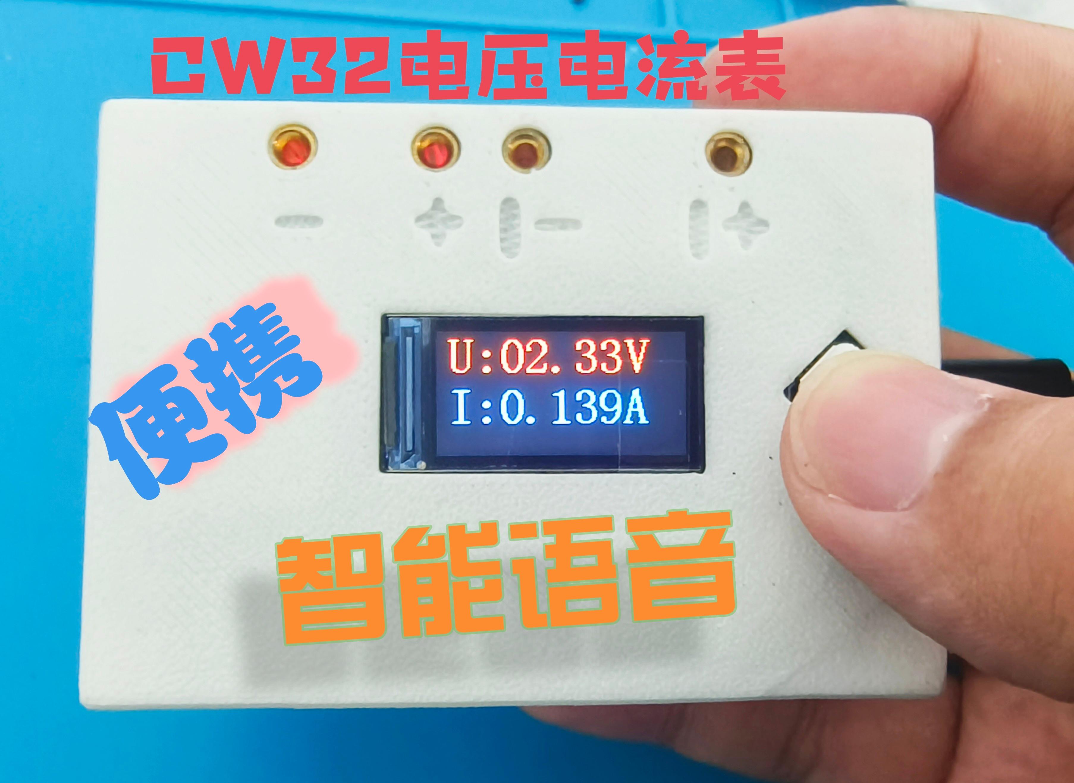
(1) Intelligent voice interaction
realizes voice dialogue, which can broadcast current and voltage values, turn on the fill light, etc.
(2) Increased quantity without increased price Increased materials without increased volume
Most components adopt common surface mount packaging, retain the original functions, upgrade to LCD high-definition display, add dazzling RGB function, RGB color soul, improve 100% performance (not really)
Optimize layout and wiring, so that the PCB area is controlled within 50mm*72mm, making it more portable. Use 3D printing to customize the shell, making the work more practical.
III. Overall Design
3.1. Requirements Analysis
Voice Interaction
Considering that the project is mainly used in daily life scenarios and may not have a stable network environment, and is also sensitive to power consumption, an offline voice interaction method is chosen.
High-Definition
Display The original case's digital tube display effect is limited, and it is recommended to replace it with an LCD to obtain a better display effect.
Lighting
The original case used ordinary lighting beads, which requires additional design of a driver circuit. To improve ease of use, WS2812 beads are used, which are sufficient for flashlight lighting and have high playability.
Power Management
The battery pack used in the original case is not portable enough, and lithium batteries have certain safety risks. A "23A 12V" battery was used for simple testing, but USB power supply is recommended for daily use.
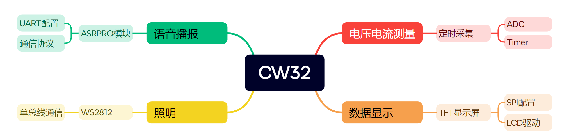
3.2 System Scheme Block Diagram
3.3 System Resources
IV. Hardware Design
The main body is designed based on the reference case. Please refer to the case for specific principles. The following is an introduction to my circuit.
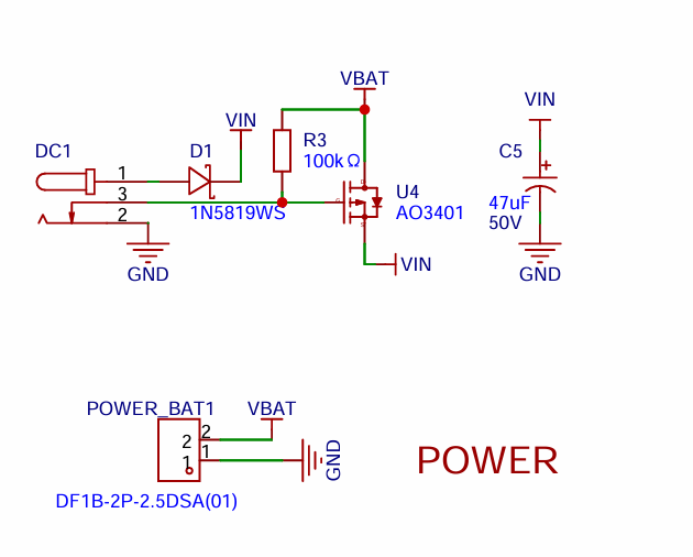
4.1. Power Circuit
The power circuit is divided into two parts: power input and LDO.
4.1.1 Power Input
The project supports both DC power and 12V battery power input. Compared to the example circuit, this one adds a MOSFET as a switch. When both DC power and a VBAT battery are connected simultaneously, the MOSFET is off, and the system uses DC as the power source.
4.1.2 The LDO circuit
is the same as the example. Here, the capacitors are changed to surface-mount capacitors. An LDO is used as the power source. Considering that most voltmeter products are used in industrial scenarios with 24V or 36V power supplies, this project chose the SE8550K2 with a maximum input voltage of up to 40V. The main reason for not using a DC-DC step-down circuit to handle large voltage differences is to avoid introducing DC-DC ripple interference during the design process; a secondary reason is to reduce project costs.

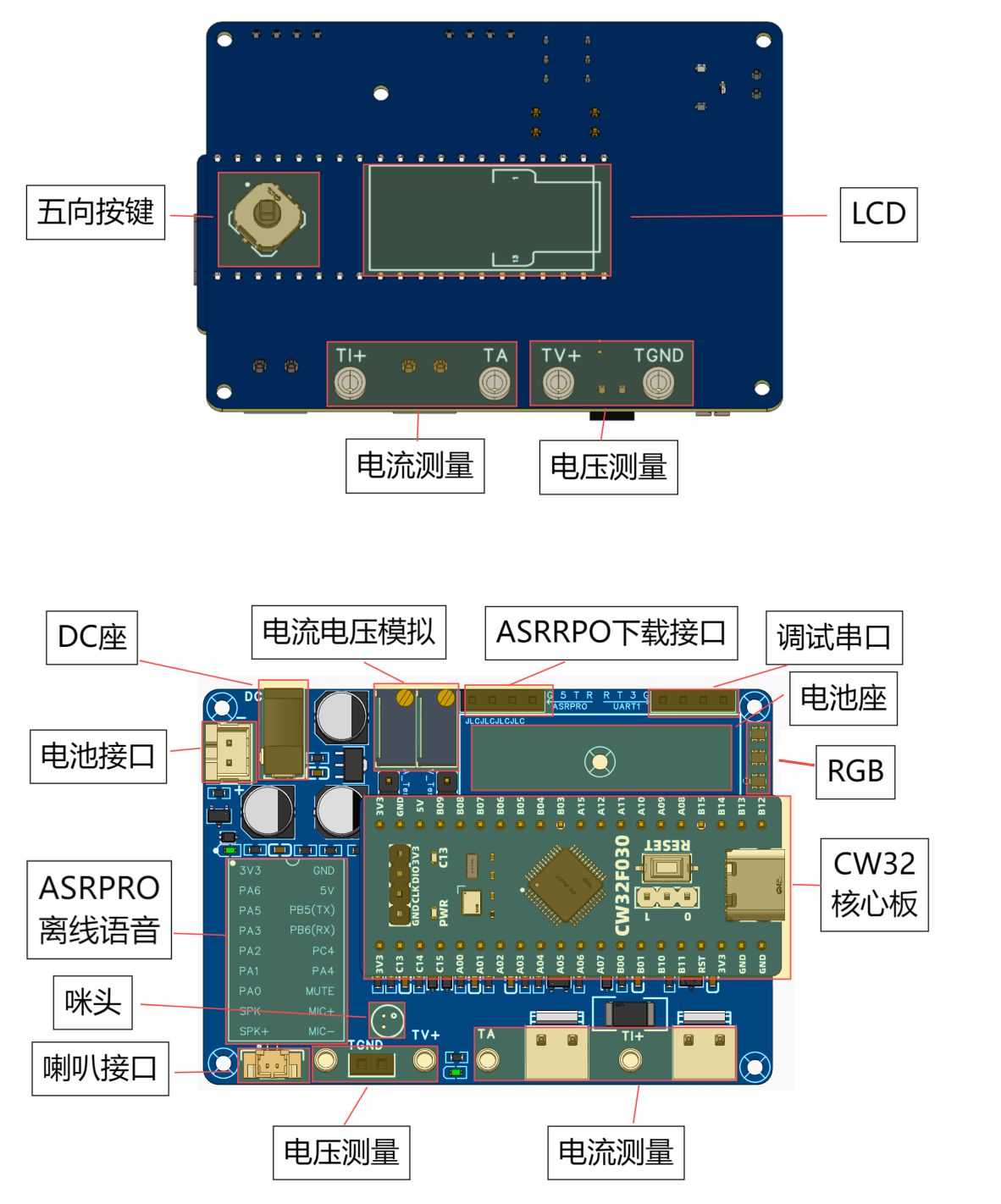
4.2 Five-way button

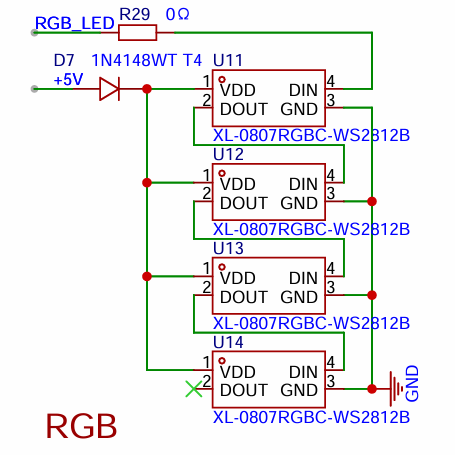
4.3 The RGB
WS2812 is a digital LED that uses single-wire serial communication. Each LED contains red, green, and blue light-emitting diodes and has a built-in control chip. Control signals are transmitted through a single data line, and the data is encoded using pulse width modulation (PWM) to determine the LED's color and brightness. Signals are passed from one LED to the next, forming a cascading effect. Four LEDs are cascaded here, powered by 5V. Actual debugging revealed that diodes improve data stability. DIN is directly connected to the microcontroller's I/O output.
4.4 The LCD circuit
references the manufacturer's application circuit design. Hardware SPI1 is used for driving.

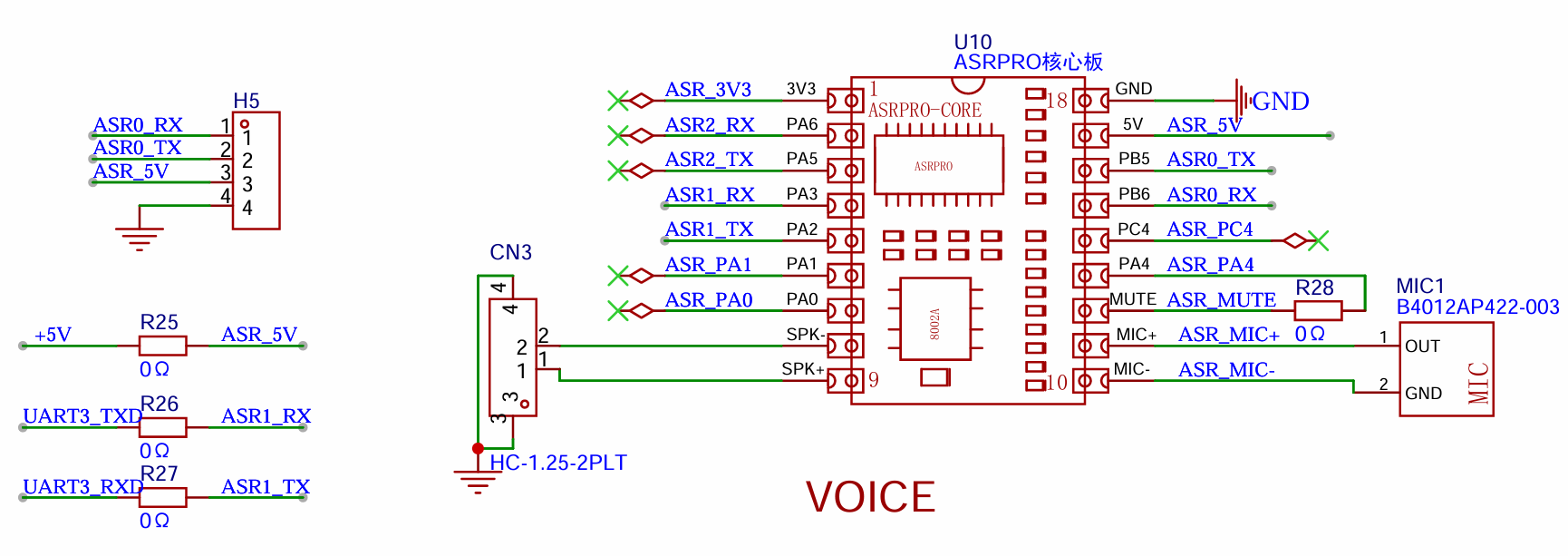
4.4 The offline voice circuit
uses ASRPRO, which is powerful and costs around 9.9 (mainly because it's cheap...).
Serial port 0 on the core board is used for program download and debugging, and serial port 1 of ASR1 is connected to the microcontroller for communication control .
V. Software Design
The program is not yet complete; a hex file is provided first. The software consists of two parts: CW32 and ASRPRO software. The focus is on the serial communication part.
5.1.
For the CW32 program driver, refer to the driver manual for adaptation. Manual link: Diwenxing Module Manual | LCSC Development Board Technical Documentation Center (lckfb.com).
An application program was written, and a simple timed execution cycle task was implemented. Every two counts, the received messages from the serial port are processed; after five counts, the average filtered voltage is calculated; after 50 counts, the screen display is updated.
void app_run(void)
{
static uint32_t time_cnt = 0;
time_cnt++;
delay_1ms(10);
if (time_cnt % 2 == 0)
app_handle_msg();
if (time_cnt % 5 == 0)
{
Volt_Cal();
}
if (time_cnt % 50)
{
char str[20] = {0};
float V_Show = (float)V_Send / 100;
if (V_Show
sprintf(str, "U:0%.2fV", V_Show);
else
sprintf(str, "U:%.2fV", V_Show);
LCD_ShowString(8, 0, (const uint8_t *)str, RED, BLACK, 32, 0);
sprintf(str, "I:%01.3fA", (float)I_Send / 1000);
LCD_ShowString(8, 32, (const uint8_t *)str, BLUE, BLACK, 32, 0);
}
}
5.2. ASRPRO Program
The ASRPRO program is developed using the accompanying Tianwen Block, and the software includes user documentation. It supports graphical programming and is easy to learn.
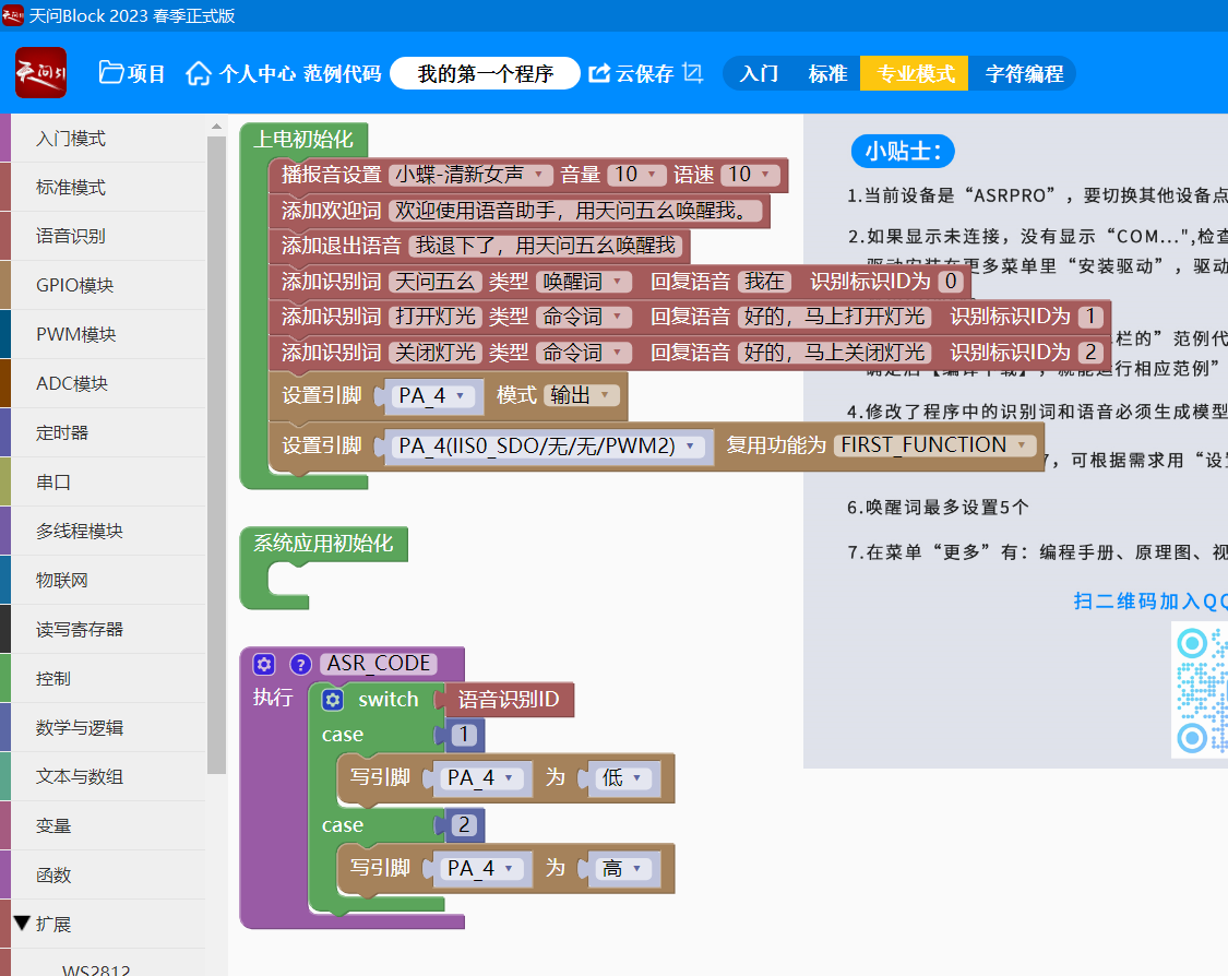
Drag and drop is not as fast as typing, so I'll use character-based programming here. The code is already integrated with FreeRTOS, so you can use it directly.
Create a thread to process the data received from the serial port. Note that to play audio, you need to wake up `enter_wakeup();` first.
The main code is as follows.
void Task_UART1Handle()
{
while (1)
{
delay(200);
if (Serial1.available() > 0)
{
//Serial1.println("read buff");
uart1_rx_string = Serial1.readString();
size_t length = uart1_rx_string.length();
if (length > 200)
continue;
delay(200);
enter_wakeup(10000);
delay(200);
char *msg_array = (char *)malloc(sizeof(char) * (length + 1));
strcpy(msg_array, uart1_rx_string.c_str());
handle_msg((const char *)msg_array, sizeof(msg_array));
free(msg_array);
msg_array = NULL;
}
//DEBUG_PRINT_FUNC("Task_UART1Handle");
}
vTaskDelete(NULL);
The
voltage and current values are displayed using movable type printing. This means displaying individual digits combined into a single unit.
A function is created to generate the corresponding audio. When needed, the audio with the corresponding ID is simply played.
void test_number()
{
//{ID:517,keyword:"command word",ASR:"fun link play",ASRTO:"zero"}
play_audio(517);
//{ID:518,keyword:"command word",ASR:"warm link play",ASRTO:"one"}
play_audio(518);
//{ID:519,keyword:"command word",ASR:"fierce link play",ASRTO:"two"}
play_audio(519);
//{ID:520,keyword:"command word",ASR:"play silk link",ASRTO:"three"}
play_audio(520);
//{ID:521,keyword:"command word",ASR:"link play",ASRTO:"four"}
play_audio(521);
//{ID:522,keyword:"command word",ASR:"official silk play",ASRTO:"five"}
play_audio(522);
//{ID:523,keyword:"command word",ASR:"silk official play",ASRTO:"six"}
play_audio(523);
//{ID:524,keyword:"command word",ASR:"grain official play",ASRTO:"seven"}
play_audio(524);
//{ID:525,keyword:"command word",ASR:"bacterial official play",ASRTO:"eight"}
play_audio(525);
//{ID:526,keyword:"command word",ASR:"pure official play",ASRTO:"nine"}
play_audio(526);
}
/*Describe this function...
*/
void test_other()
{
//{ID:527,keyword:"command word",ASR:"fun official play",ASRTO:"fun"}
play_audio(527);
//{ID:528,keyword:"command word",ASR:"warm official play",ASRTO:"peaceful"}
play_audio(528);
//{ID:529,keyword:"command word",ASR:"fierce official play",ASRTO:"Opening"}
play_audio(529);
//{ID:530,keyword:"command word",ASR:"shuttle grain connect",ASRTO:"closing"}
play_audio(530);
//{ID:531,keyword:"command word",ASR:"connect grain play",ASRTO:"point"}
play_audio(531);
//{ID:532,keyword:"command word",ASR:"official grain play",ASRTO:"voltage"}
play_audio(532);
//{ID:533,keyword:"command word",ASR:"silk grain play",ASRTO:"current"}
play_audio(533);
//{ID:534,keyword:"command word",ASR:"grain silk play",ASRTO:"for"}
play_audio(534);
}
To announce the 3.3V voltage, play the following in sequence (note that to announce the audio, you need to wake up enter_wakeup() first):
//"Voltage"
play_audio(532);
//"for"
play_audio(534);
//"three"
play_audio(520);
//"point"
play_audio(531);
//"three"
play_audio(520);
//"volt"
play_audio(527);
5.3 Communication Processing Program
The communication protocol is very simple. Each frame ends with a newline character (0x0d 0x0a).
First, let's introduce the CW32 receiving program.
void UART3_IRQHandler(void)
{
if (USART_GetITStatus(CW_UART3, USART_IT_RC) != RESET)
{
// Receive one byte
g_rx_data3[0] = USART_ReceiveData_8bit(CW_UART3);
// Clear the flag
USART_ClearITPendingBit(CW_UART3, USART_IT_RC);
if ((g_usart3_rx_sta & 0x8000) == 0) /* Receive not complete */
{
if (g_usart3_rx_sta & 0x4000) /* Received 0x0d (i.e., Enter key) */
{
if (g_rx_data3[0] != 0x0a) /* Received not 0x0a (i.e., not newline key) */
{
g_usart3_rx_sta = 0; /* Receive error, restart */
}
else /* Received 0x0a (newline key) */
{
g_usart3_rx_sta |= 0x8000; /* Reception completed */
}
}
else /* 0X0d (Enter key) not received yet */
{
if (g_rx_data3[0] == 0x0d)
g_usart3_rx_sta |= 0x4000;
else
{
g_usart3_rx_buf[g_usart3_rx_sta & 0X3FFF] = g_rx_data3[0];
g_usart3_rx_sta++;
if (g_usart3_rx_sta > (USART_REC_LEN - 1))
{
g_usart3_rx_sta = 0; /* Data received error, restart receiving */
}
}
}
}
}
}
The high two bits of `g_usart3_rx_sta` are the receive flags, and the following 14 bits record the length. `g_usart3_rx_sta` equal to 0x8000 indicates successful reception.
The function to get the received length is:
`uint16_t uart3_get_receive_len(void)
{
return (g_usart3_rx_sta & 0x8000) ? (g_usart3_rx_sta & 0x3FFF) : 0;
}`.
Communication format:
For example, for the "turn on lights" command, D=1
. The frame header is defined using an enumeration:
`enum MSG_FRAM_HEAD_t
{
MSG_VOLTAGE_HEAD = 'U',
MSG_CURRET_HEAD = 'I',
MSG_LED_HEAD = 'D',
MSG_MUTE_HEAD = 'M',`
};
The code that handles the received data uses a switch statement to match the processing function for the corresponding frame header.
static int app_uart3_hanle_rec(const char *buff, unsigned short len)
{
if (NULL == buff || len > BUFFER_MAX_SIZE)
return -127;
// handle
switch (buff[0])
{
case MSG_VOLTAGE_HEAD:
handle_voltage(buff, len);
break;
case MSG_CURRET_HEAD:
handle_current(buff, len);
break;
case MSG_LED_HEAD:
handle_led(buff, len);
break;
default:
return -126;
}
return 0;
}
When D=1 is received, it is the control of the LED, and the processing function is as follows.
static int handle_led(const char *buff, unsigned short len)
{
unsigned short index = 2;
if (buff[1] != MSG_FLAG_SEPARATOR && len > 20)
{
return -1;
}
else
{
if (buff[index] == '0') // D=0
{
rgb_off();
}
else if (buff[index] == '1')
{
rgb_on();
}
else
{
LED_Toggle();
}
}
return 0;
}
Other processing functions follow the same logic. To facilitate the broadcasting of floating-point voltage and current data, they can be multiplied by 100 or 1000 and transmitted as integers.
void Volt_Cal(void)
{
V_Buffer = Mean_Value_Filter(Volt_Buffer, ADC_SAMPLE_SIZE); // Use mean filtering
I_Buffer = Mean_Value_Filter(Curr_Buffer, ADC_SAMPLE_SIZE); // Use mean filtering
V_Send = ((float)V_Buffer/4095)*1.5*(220+10)/10 * 100;
I_Send = ((float)I_Buffer/4095)*1.5*10 * 1000;
}
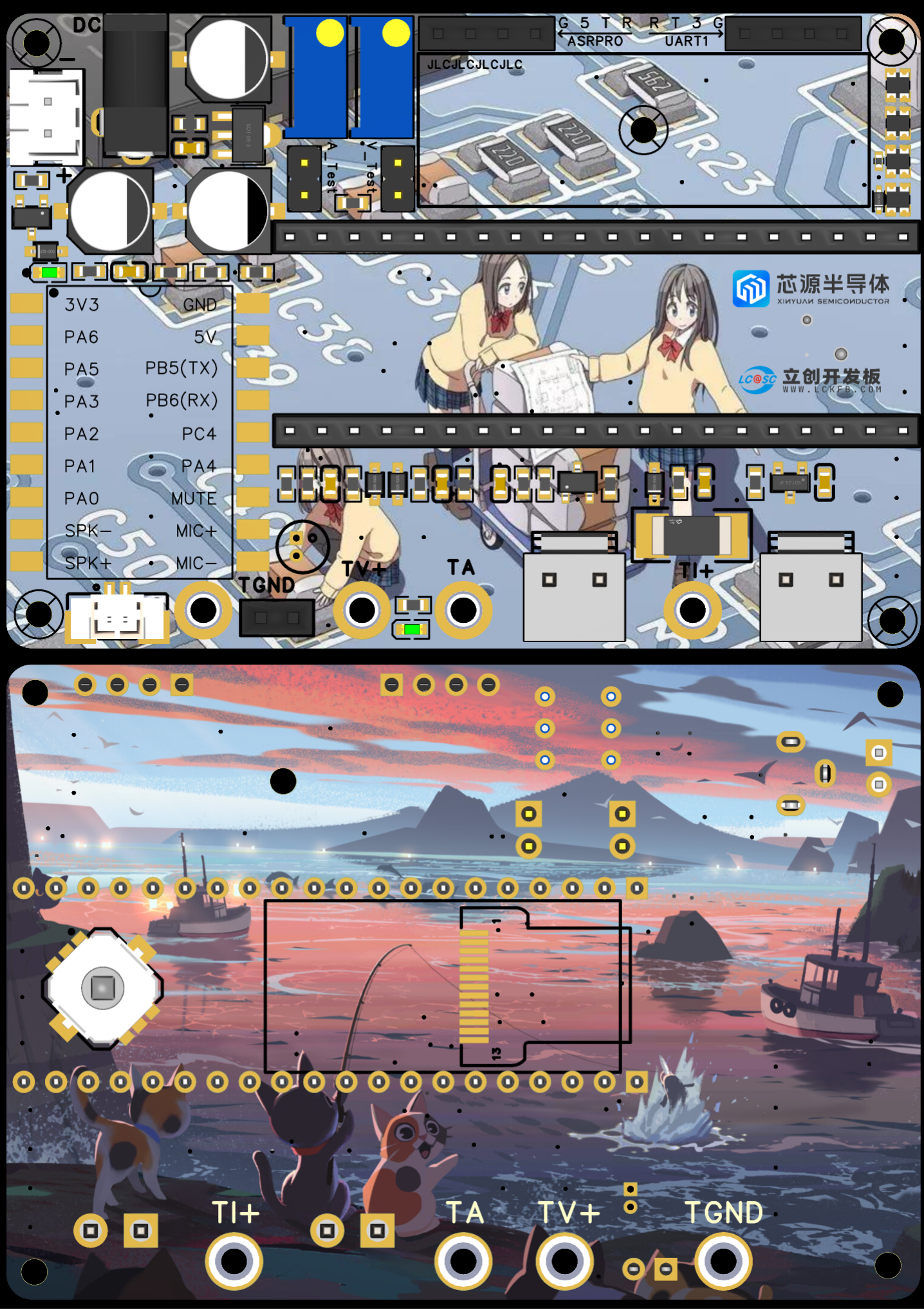
VI. Demonstrating
the PCB layout
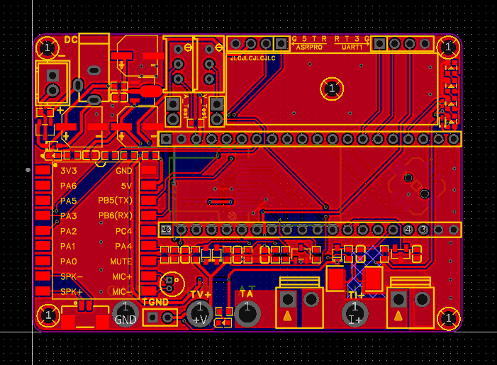
rendering:
The color silkscreen is really sweet and beautiful.
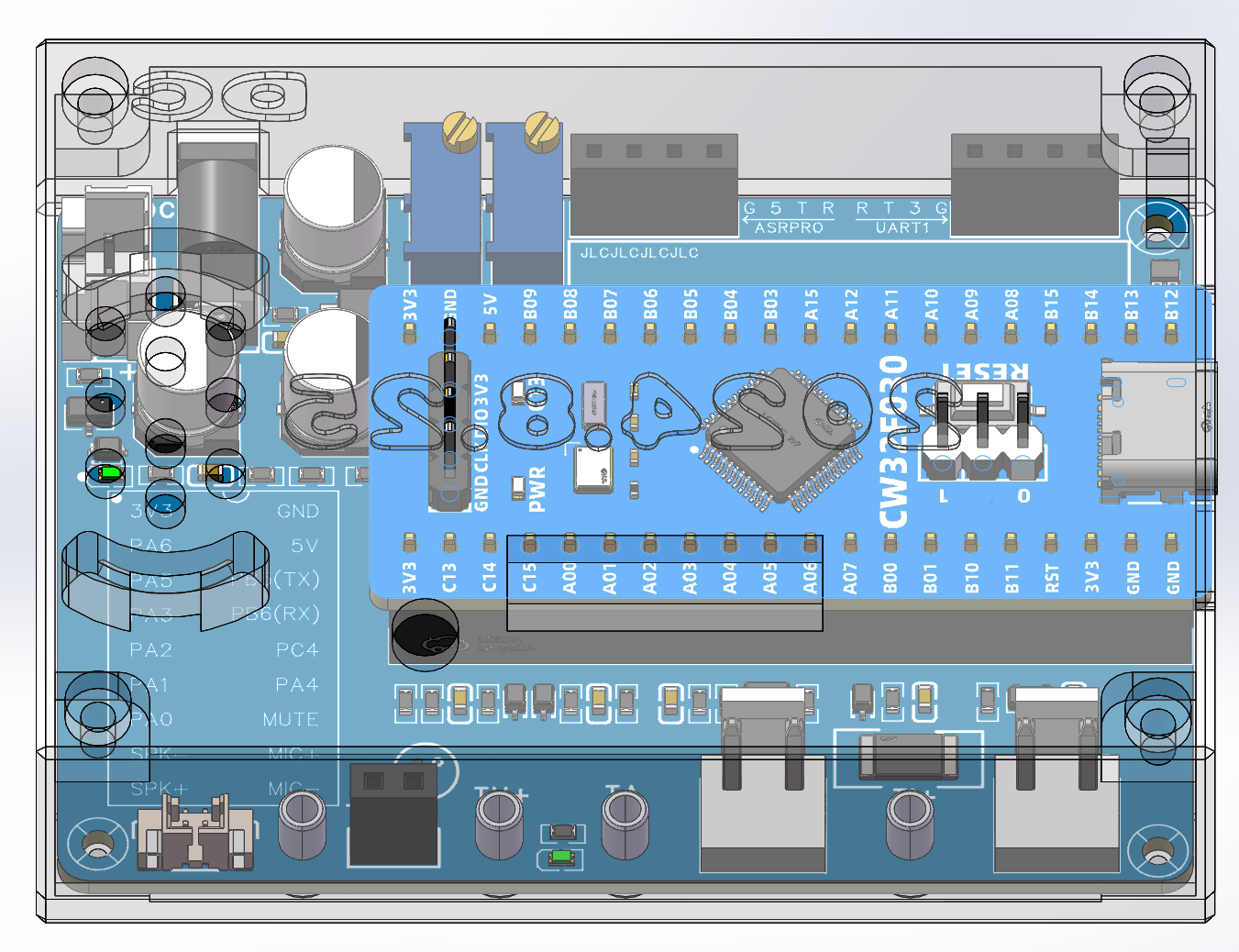
In order to achieve the coordination and unity of the small blue board, the blue board was soldered first.
The blue board was debugged first, and then the color silkscreen was soldered after it was determined. Sigh~
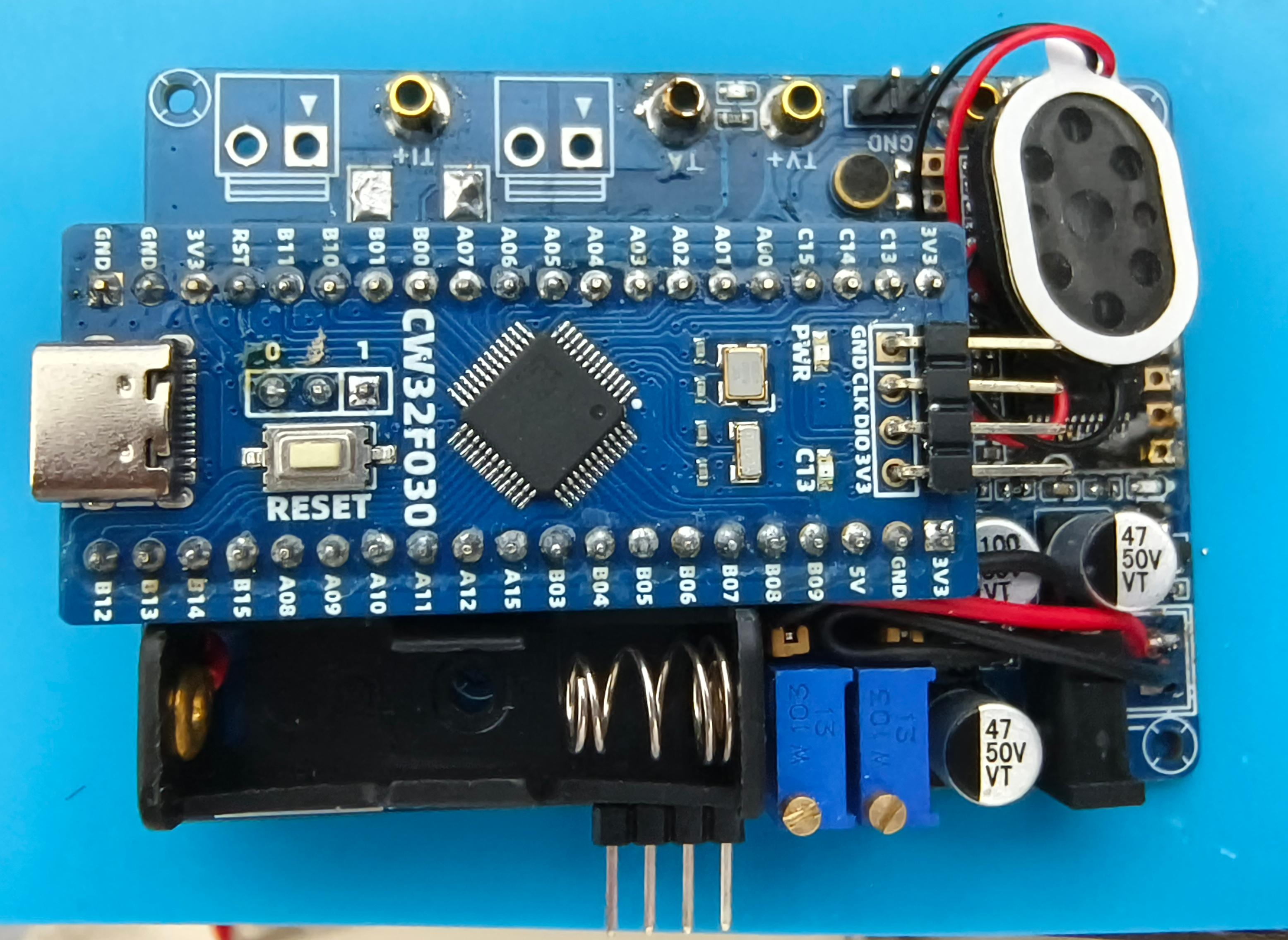
The shell model rendering and
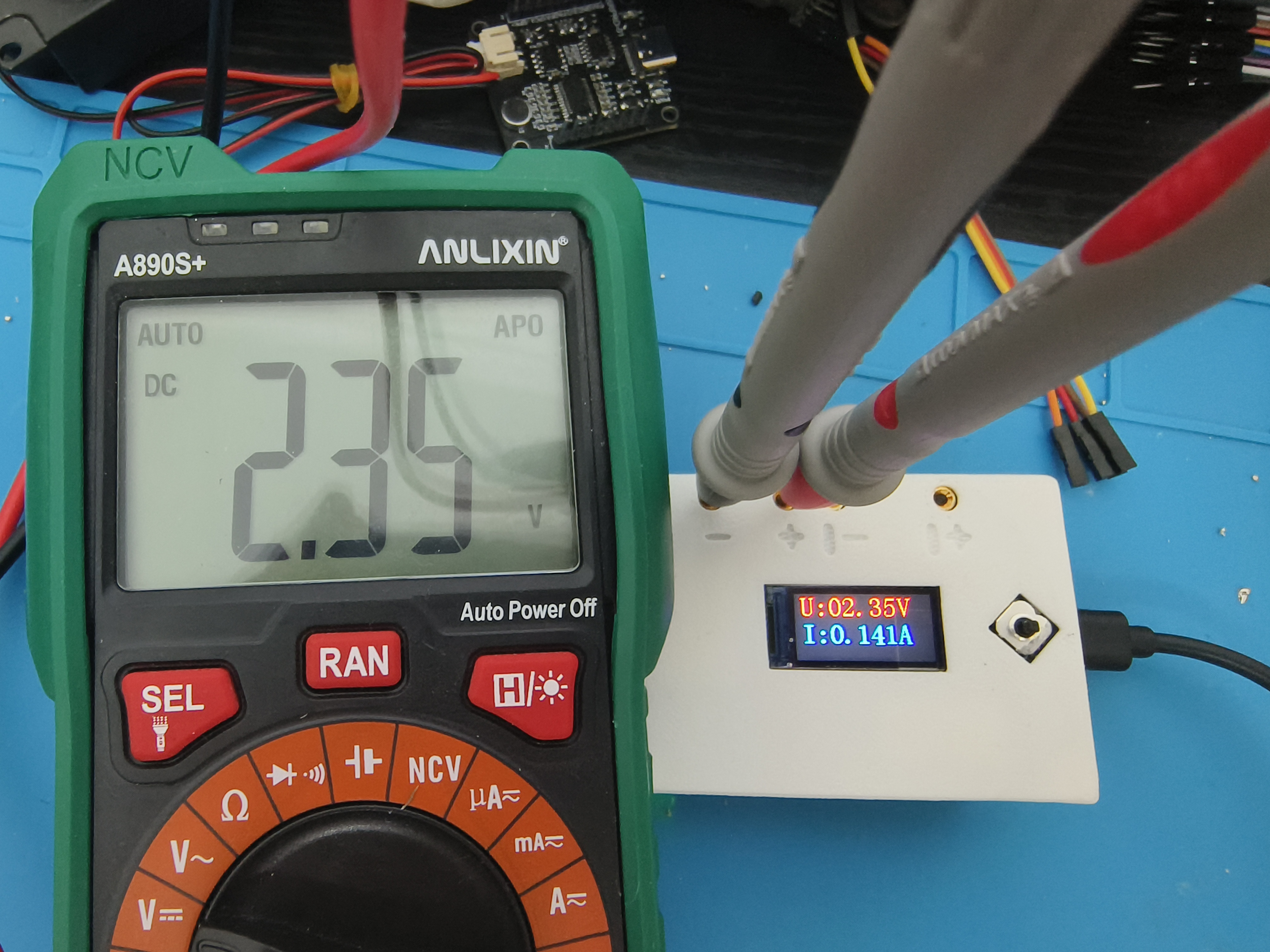
physical display

are compared with my own multimeter. This ADC is pretty awesome.
VII. Summary:
Voltage and current production completed.
Thanks to LCSC and CW32.
Video Link: https://b23.tv/qsXpQAJ
VIII. Material Purchase and Others:
These are all common materials that can be purchased.
The voice module core board can be found by searching "ASRPRO voice" on Taobao.
The speaker is oval-shaped, size 2014, and includes a plug.
I'll add more as I think of them later.
Please like, save, and follow. Feel free to ask questions.


 京公网安备 11010802033920号

 1CIS101-01GGRTV


