Function Description:
1. Data Acquisition: Single-channel data acquisition using the core board's ADC function.
2. Adjustable Signal Attenuation: Through resistor voltage division, it can be set to 50X, 10X, etc., with 10X recommended.
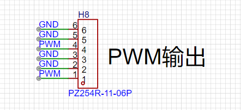
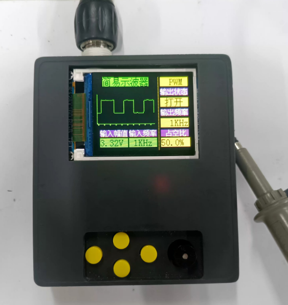
3. Supports PWM square wave output: 1K, 2K, 4KHz output, with adjustable duty cycle in 5% steps.
4. Waveform Display: Displayed on a 1.8-inch TFT screen with a resolution of 128X160.
5. Compatible with multiple core boards including CW32, GD32, and STM32.
6. Supports Frequency Measurement: Achieved through the MCU's GPIO capture function.
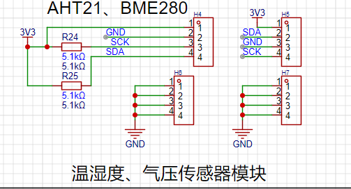
7. Reserved sensor interfaces, such as temperature and humidity sensors, barometers, etc.
Design Background
: Oscilloscopes are indispensable tools for electronic engineers. They are divided into analog and digital oscilloscopes based on the signal type. Analog oscilloscopes use analog circuits and electron guns to display waveforms by projecting an electron beam onto the screen, while digital oscilloscopes use digital circuits and digital storage technology to digitize and display the waveform.

Analog Oscilloscopes vs. Digital Oscilloscopes (e.g., Rigol DS6104):
In the process of oscilloscope upgrades and iterations, traditional analog oscilloscopes can no longer meet the needs of modern electronic measurements. Compared to analog oscilloscopes, digital oscilloscopes offer higher measurement accuracy, more stable display, and better signal transmission. With technological advancements, the performance and functionality of oscilloscopes continue to improve. Modern oscilloscopes utilize technologies such as high-speed ADCs and FPGAs, featuring high bandwidth, high sampling rates, and deep memory depth. Furthermore, digital oscilloscopes support various triggering methods and signal analysis functions, such as FFT transformation and spectrum analysis.
To learn how to use the CW32 core board as the main controller, this study will explore the construction method of a simple oscilloscope.
The implementation process involves
circuit principle analysis
. A digital oscilloscope is an instrument used to display electrical signal waveforms, mainly composed of analog front-end processing circuits, microcontroller circuits, power supply circuits, control circuits, triggering circuits, calibration circuits, and other circuits. As this project is an introductory oscilloscope project, several core circuits were selected in the circuit design to help beginners better understand the principles and design methods of oscilloscopes. These mainly include the following circuits:
Analog front-end processing circuit: responsible for processing the input analog signal and then sending it to the microcontroller for identification. Specific circuits include AC/DC coupling selection circuit, voltage attenuation circuit, signal processing circuit, and frequency detection circuit, which is the core of the entire circuit.
Power supply circuit: responsible for providing positive and negative power to the operational amplifier and system power, ensuring the normal operation of the circuit.
Microcontroller circuit: provides the control core of the system, responsible for the acquisition, processing, and output of input signals.
Human-machine interface circuit: used to control oscilloscope functions, including buttons, knobs, LEDs, display screen, and other input/output interfaces, providing a foundation for the development of oscilloscope functions.
Schematic Design of
Analog Front-End Processing Circuit
: In the entire oscilloscope circuit design process, the analog front-end processing circuit is the most important. It extensively utilizes knowledge of analog circuits, including an input AC/DC coupling switching circuit, an input signal attenuation circuit, and a signal conditioning circuit.
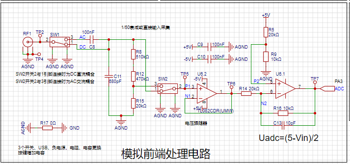
The AC/DC coupling switching circuit
can classify signal types into DC and AC signals. Real-world signals are often not ideal waveforms. For example, a DC power supply signal should be a horizontal DC signal, but it will always contain power supply ripple (AC signal). When acquiring AC signals, DC signals may also be mixed in, affecting the peak-to-peak value of the waveform. To ensure accurate measurement of the input AC signal, the characteristic of a capacitor to pass AC and block DC is utilized. By connecting a capacitor in series with the circuit, the DC component in the signal can be filtered out; this is the concept of AC coupling. DC coupling, on the other hand, involves not processing the input signal in any way.

The input signal attenuation circuit,
after passing through the AC/DC coupling selection circuit, uses switch SW3 to select two channels. When switches 2 and 3 are connected together, the input signal flows directly into the subsequent voltage follower circuit. When switches 2 and 1 are connected together, the input signal is attenuated to 1/50th of its original value after passing through a resistor divider network composed of resistors R8, R12, and R15. That is,
when switches 2 and 1 are connected together, the measurable input signal amplitude is -1.6V to 5V;
when switches 2 and 3 are connected together, the measurable input signal amplitude is -80V to 250V.
Therefore, when the input signal amplitude is small, the lower voltage range should be selected first. If the input signal amplitude is uncertain during measurement, the higher voltage range can be used first. If it falls within the lower voltage range, the lower voltage range can be used to obtain a more accurate measurement result, while simultaneously protecting the circuit.
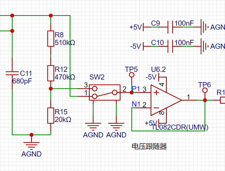
The signal conditioning
circuit includes a voltage follower and a signal amplification circuit composed of operational amplifiers. When analyzing this part of the circuit, it is necessary to understand the virtual open and virtual short principles of operational amplifiers.
(1) Voltage Follower Circuit:
In the U6.2 chip, the inverting input pin 2 of the op-amp is connected to the output pin 1 of the op-amp. Combined with the virtual short characteristic of the op-amp, V+=V-=Vout. According to the virtual open circuit, the input impedance of the op-amp is relatively large, so the forward input current of the op-amp is very small. The output impedance of the op-amp is small, so the output current is very large. It is said that the voltage follower here plays the role of impedance matching.
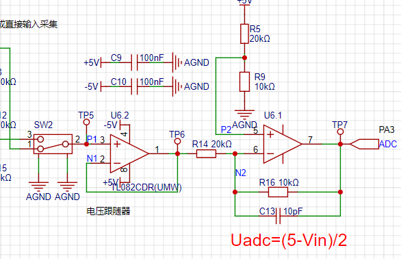
(2) Proportional Amplifier Circuit
: When analyzing the circuit composed of the op-amp U6.1, it can be decomposed into a non-inverting proportional amplifier circuit and an inverting proportional amplifier circuit for separate analysis and then combined together.
Low voltage range measurement range: -1.6V~5V, high voltage range measurement range: -80V~250V.
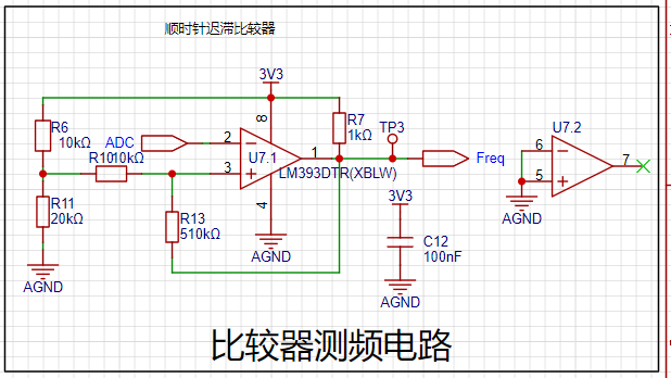
Comparator Frequency Measurement Circuit :
In order to realize the frequency detection function, the ADC input signal is compared with the input signal through a hysteresis comparator to realize the frequency measurement function. A hysteresis comparator is a type of voltage comparator. A conventional voltage comparator is a single-threshold comparator, meaning the circuit has only one threshold voltage. However, even a small change in the input voltage near the threshold will cause a significant change in the output voltage. To enhance the circuit's anti-interference capability, positive feedback is introduced into the single-threshold comparator, ensuring signal stability within a certain range. The hysteresis comparator circuit outputs a square wave signal, and the microcontroller's timer capture function is used to calculate the period of the input waveform.
The rotary encoder circuit
is a special type of button. The EC11 rotary encoder used in this project has five pins. Pins D and E are similar to ordinary button pins; they are activated when pressed and deactivated when released. The remaining three pins,
A, B, and C, are used to detect the rotation direction of the knob. Pin C is the common terminal and can be directly grounded. During rotary encoder operation, there is a phase difference between the A and B signal pins. That is, a change in the signal on one pin precedes a change in the signal on the other pin; the two pins do not change simultaneously. By detecting which pin changes first, the clockwise or counterclockwise rotation function can be determined.

The LED indicator circuit
is relatively simple in design, using a low-level drive method. When the microcontroller pin outputs a low level, a potential difference exists across the LED, and the LED lights up; when the microcontroller pin outputs a high level, the LED turns off.

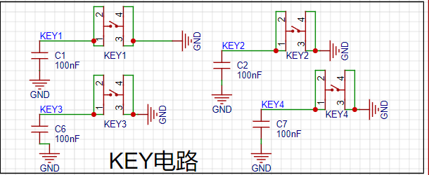
Key input detection circuit.
In addition to the rotary encoder, this project also uses four independent buttons to control the system. One side of each button is directly grounded, and the other side is connected to a microcontroller pin. When the microcontroller pin detects a button press, it connects directly to GND (Ground). The microcontroller receives this grounding signal and then executes the corresponding function. To save hardware costs, debouncing can be introduced in the software design to avoid false triggering due to mechanical button bounce.
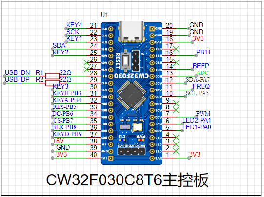
The main controller selected
is the LCSC CW32F030C8T6 development board, a microcontroller development board based on the ARM Cortex-M0 core, provided by LCSC Mall (LCSC website). The following is a detailed introduction to this development board:
Basic Information
: Brand and Model: LCSC development board, model LCKFB-DWX-CW32F030C8T6.
Processor: Equipped with a CW32F030C8T6 microcontroller, a 32-bit MCU based on the ARM Cortex-M0 core, suitable for low-power, high-performance embedded applications.
Features and Functionality
Extensibility: Offers rich expansion interfaces, such as the SMT extension library, facilitating secondary development and functional expansion according to user needs.
Debugging and Programming: Supports efficient debugging and program burning using debugging tools such as J-Link, improving development efficiency. It also supports programming in development environments such as Keil.
Low Power Consumption: Utilizing a Cortex-M0 core, this development board features low power consumption, suitable for applications with strict power requirements.
Accessories and Documentation
: Accessories: Typically, this development board comes with two 1x20P straight headers, one 1x4P right-angle header, and one instruction manual. Please note that these accessories may not be covered by after-sales service. Documentation:
A detailed datasheet (PDF format) is provided, which users can download and consult through channels such as LCSC Online Store for better understanding and use of the development board.
Purchase and Inventory
Pricing: According to LCSC Online Store, the price of this development board is relatively affordable; however, the specific price may vary due to promotional activities and other factors.
Inventory: LCSC Online Store has warehouses in Jiangsu and Guangdong, with ample inventory, so users can purchase with confidence.
Development and Usage
: It is recommended to use an Integrated Development Environment (IDE) such as Keil for program development. These environments provide rich features and tools, helping users get started quickly and develop efficiently.
Application Scenarios: Due to its low power consumption and high performance, the LCSC Diwenxing CW32F030C8T6 development board is suitable for various embedded application scenarios, such as smart homes, industrial automation, and IoT devices.
In summary, the LCSC Diwenxing CW32F030C8T6 development board is a cost-effective and feature-rich microcontroller development board suitable for a wide range of embedded developers. The 1.8-inch TFT
LCD display circuit
is a color display with 128 x 160 color pixels. It connects to the microcontroller using a four-wire SPI communication method, with a total of eight pins. The module pin description and connection to the microcontroller are as follows:
Pin Number
Pin Name
Pin Description

1. GND Power Ground Pin
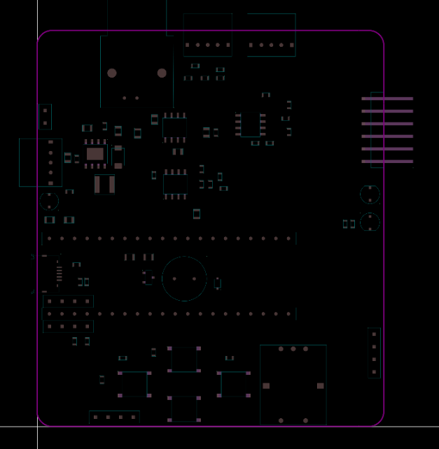
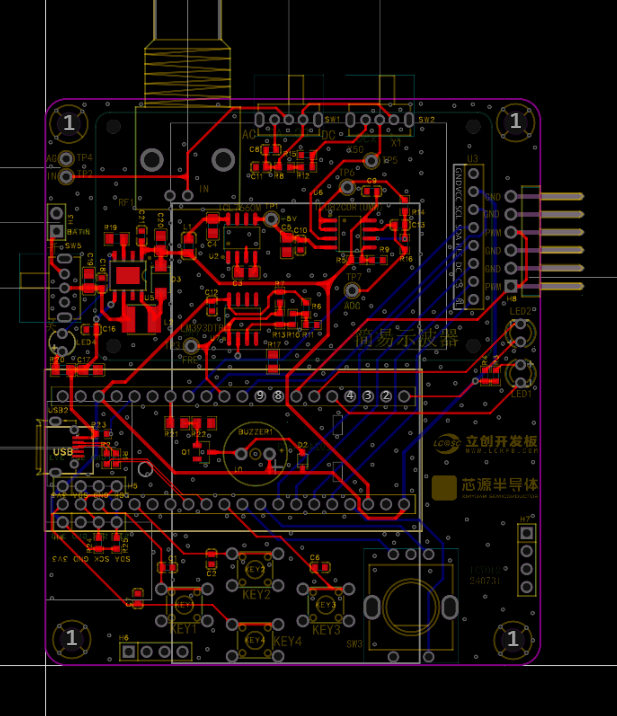
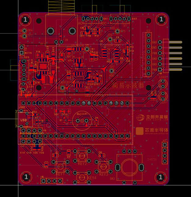
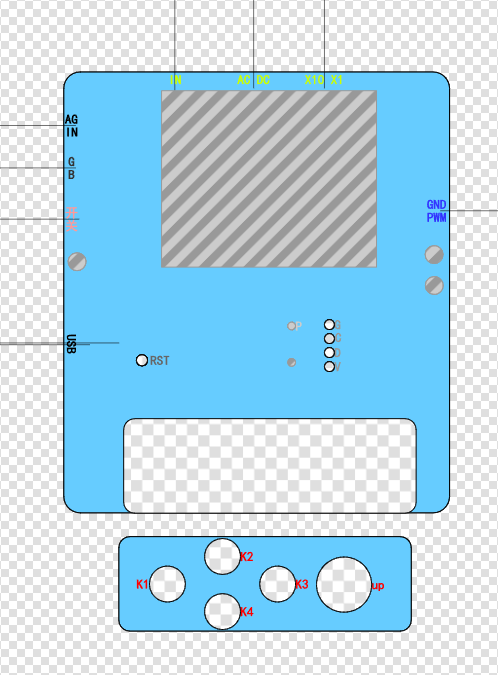
2 VCC Power Supply 3 SCL SPI Serial Clock Signal 4 SDA SPI Data Pin (MOSI) 5 RES Reset Pin 6 DC Command and Data Select Pin 7 CS LCD Chip Select Pin 8 BL Backlight Pin The power supply design supports lithium battery power and USB power. USB charging is used. Other circuits, in addition to the oscilloscope detection function, have a separate PWM signal to simulate a simple function generator function. By changing the frequency and duty cycle of the output PWM, a simple square wave signal can be output. A sensor interface is also reserved, supporting AHT21 and BMP280 access. The PCB design is carried out using LCEDA open source software. The layout design is compact, convenient and practical. The trace design should be as short as possible. Based on EMC and EMI principles, wire diameter and vias should be designed, and power traces should be designed according to load capacity and current carrying capacity. Ground segmentation is implemented to separate analog and digital grounds. The enclosure design uses LCEDA open-source software, paying particular attention to precise hole placement and tolerance allowances; otherwise, installation will be impossible. The panel design also uses LCEDA open-source software, again emphasizing the importance of precise hole placement and tolerance allowances; otherwise, misalignment will be unsightly and installation will be difficult. Labels should be clear, accurate, and easily identifiable. The main control code implementation of the program is as follows: #include "main.h" #include "tft.h" #include "tft_init.h" #include "led.h" #include "adc.h" #include "timer.h" #include "freq.h" #include "key.h" void RCC_Configuration(void); volatile struct Oscilloscope oscilloscope={0}; void Init_Oscilloscope(volatile struct Oscilloscope *value); extern uint16_t adc_value[ADC_VALUE_NUM]; int main() { uint16_t i=0; // intermediate value float median=0; // peak-to-peak value


float voltage=0,vpp=0;
// Trigger voltage value
float max_data=2.5f;
// Waveform amplification factor
float gainFactor=15.0f;
// Trigger edge marker
uint16_t Trigger_number=0;
// Initialize oscilloscope parameters
Init_Oscilloscope(&oscilloscope);
// Clock initialization
RCC_Configuration();
// LED initialization
Init_LED_GPIO();
// Screen initialization
TFT_Init();
// Initialize ADC pins
Init_ADC(oscilloscope.ADC_ClkDiv,oscilloscope.ADC_SampleTime);
// ADC DMA initialization
ADC_DMA_Init();
// Fill with black
TFT_Fill(0,0,160,128,BLACK);
// Initialize PWM output
Init_PWM_Output(oscilloscope.timerPeriod-1,oscilloscope.pwmOut);
// Initialize EC11 pin
Init_EC11_GPIO();
// Initialize button pin
Init_Key_GPIO();
// Initialize frequency timer
Init_FreqTimer();
// Initialize static UI
TFT_StaticUI();
while(1)
{
// Key scan processing function
Key_Handle(&oscilloscope);
if(oscilloscope.showbit==1)
{
oscilloscope.showbit=0;
oscilloscope.vpp=0;
// Convert voltage value
for(i=0;i
{
oscilloscope.voltageValue[i]=(adc_value[i]*3.3f)/4096.0f;
// Get peak voltage of the entire data segment
vpp=(5-(2.0f*oscilloscope.voltageValue[i]));
if((oscilloscope.vpp)
{
oscilloscope.vpp = vpp;
}
if(oscilloscope.vpp
{
oscilloscope.gatherFreq=0;
}
}
// Find the starting display waveform value
for(i=0;i
{
if(oscilloscope.voltageValue[i]
{
for(;i
{
if(oscilloscope.voltageValue[i] > max_data)
{
Trigger_number=i;
break;
}
}
break;
}
}
// If the amplitude is too small, the amplification factor will be too large, causing the waveform display to be abnormal.
if(oscilloscope.vpp > 0.3)
{
// Calculate the intermediate amplitude. The lowest input point is 2.5V, and the highest is (5-vpp)/2. The intermediate amplitude is the lowest value minus the highest value/2.
median = (2.5-(5 - oscilloscope.vpp)/2.0f)/2.0f;
// Amplification factor. It is necessary to determine the range after amplification. I fix the waveform display in (18.75~41.25). (41.25-18.75)/2=11.25f
gainFactor = 11.25f/median;
// The lowest value minus the median amplitude equals the median value
median = 2.5 - median;
}
// Display the next 100 data points sequentially to prevent waveform scrolling
for(i=Trigger_number;i
{
if(oscilloscope.keyValue == KEYD)
{
oscilloscope.keyValue=0;
do
{
if(oscilloscope.keyValue == KEYD){
oscilloscope.keyValue=0;
break;
}
// After pausing, judge the waveform frequency and change the ADC sampling rate to make the waveform display optimal
if(oscilloscope.gatherFreq
{
oscilloscope.ADC_ClkDiv=ADC_Clk_Div128;
}
else if(oscilloscope.gatherFreq
{
oscilloscope.ADC_ClkDiv=ADC_Clk_Div64;
}
else if(oscilloscope.gatherFreq
{
oscilloscope.ADC_ClkDiv=ADC_Clk_Div32;
}
else if(oscilloscope.gatherFreq
{
oscilloscope.ADC_ClkDiv=ADC_Clk_Div16;
}
else if(oscilloscope.gatherFreq
{
oscilloscope.ADC_ClkDiv=ADC_Clk_Div8;
}
else if(oscilloscope.gatherFreq
{
oscilloscope.ADC_ClkDiv=ADC_Clk_Div4;
}
else
{
oscilloscope.ADC_ClkDiv=ADC_Clk_Div2;
}
}while(1);
Init_ADC(oscilloscope.ADC_ClkDiv,oscilloscope.ADC_SampleTime);
}
voltage=oscilloscope.voltageValue[i];
if(voltage >= median)
{
voltage = 30 - (voltage - median)*gainFactor;
}
else
{
voltage = 30 + (median - voltage)*gainFactor;
}
drawCurve(80,voltage);
}
ADC_DMA_Init();
}
//Parameter display UI
TFT_ShowUI(&oscilloscope);
}
}
void RCC_Configuration(void) //External clock 8M, PLL:64M
{
RCC_AHBPeriphClk_Enable(RCC_AHB_PERIPH_FLASH, ENABLE); //Enable FLASH clock
RCC_HSE_Enable(RCC_HSE_MODE_OSC, 8000000, RCC_HSE_DRIVER_NORMAL, RCC_HSE_FLT_CLOSE); //Enable external high-speed clock HSE, the actual frequency needs to be filled in according to the actual crystal frequency
RCC_PLL_Enable(RCC_PLLSOURCE_HSEOSC, 8000000, RCC_PLL_MUL_8); // Enable PLL, PLL clock source is HSE
FLASH_SetLatency(FLASH_Latency_3);
FirmwareDelay(100000); // Sufficient delay to ensure clock stability
if (RCC_SysClk_Switch(RCC_SYSCLKSRC_PLL) == 0x0U) // Successfully switched system clock
{
RCC_HSI_Disable(); // Disable source clock HSI
FirmwareDelay(400000);
}
}
/*
* Function content: Initialize oscilloscope parameter structure
* Function parameter: volatile struct Oscilloscope *value -- pointer to oscilloscope parameter structure
* Return value: None
*/
void Init_Oscilloscope(volatile struct Oscilloscope *value)
{
(*value).showbit = 0; // Clear display flag
(*value).ADC_ClkDiv = ADC_Clk_Div64; // ADC clock
(*value).ADC_SampleTime = ADC_SampTime10Clk; // ADC clock cycle
(*value).keyValue = 0; // Clear key value
(*value).outputbit = 0; // Output flag
(*value).gatherFreq = 0; //Sampling frequency
(*value).outputFreq =1000; //Output frequency
(*value).pwmOut =500; //PWM duty cycle of PWM pin output
(*value).timerPeriod =1000; //PWM output timer period
(*value).vpp =0.0f; //Peak-to-peak value
}
See the attachment for other code. See the Bilibili demo for a demonstration:
https://www.bilibili.com/video/BV15FWretEfv/?vd_source=e36622a05269c0356d6cd566056a2488 In summary, the CW32's ADC is more accurate and has lower noise than STM32 and GD32. Domestic chips are indeed well-made. This deserves praise. Through this training camp, I also learned that the CW32, a niche product, does have some amazing aspects, such as the ADC reference voltage selection of internal 1.5V, 2.5V, etc. Previously, an external reference power supply was needed for a more stable power supply, which was expensive and difficult to design. This learning experience allowed me to meet many experts and learn a great deal. Thank you LCSC and Sinyuan.


 京公网安备 11010802033920号

 1.5KE150CA-T3


