This is the simplest USB to dual serial port
STC adapter, a very basic tool that can be used as a programmer for other STC microcontrollers. It comes in
an SOP16 package, is easy to solder
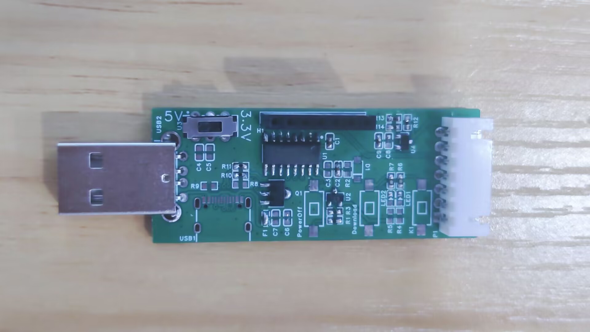
, and offers selectable 3.3V/5V output power. It supports manual control via a K1 button
and can be used as a USB development board. It is compatible with official STC source code examples
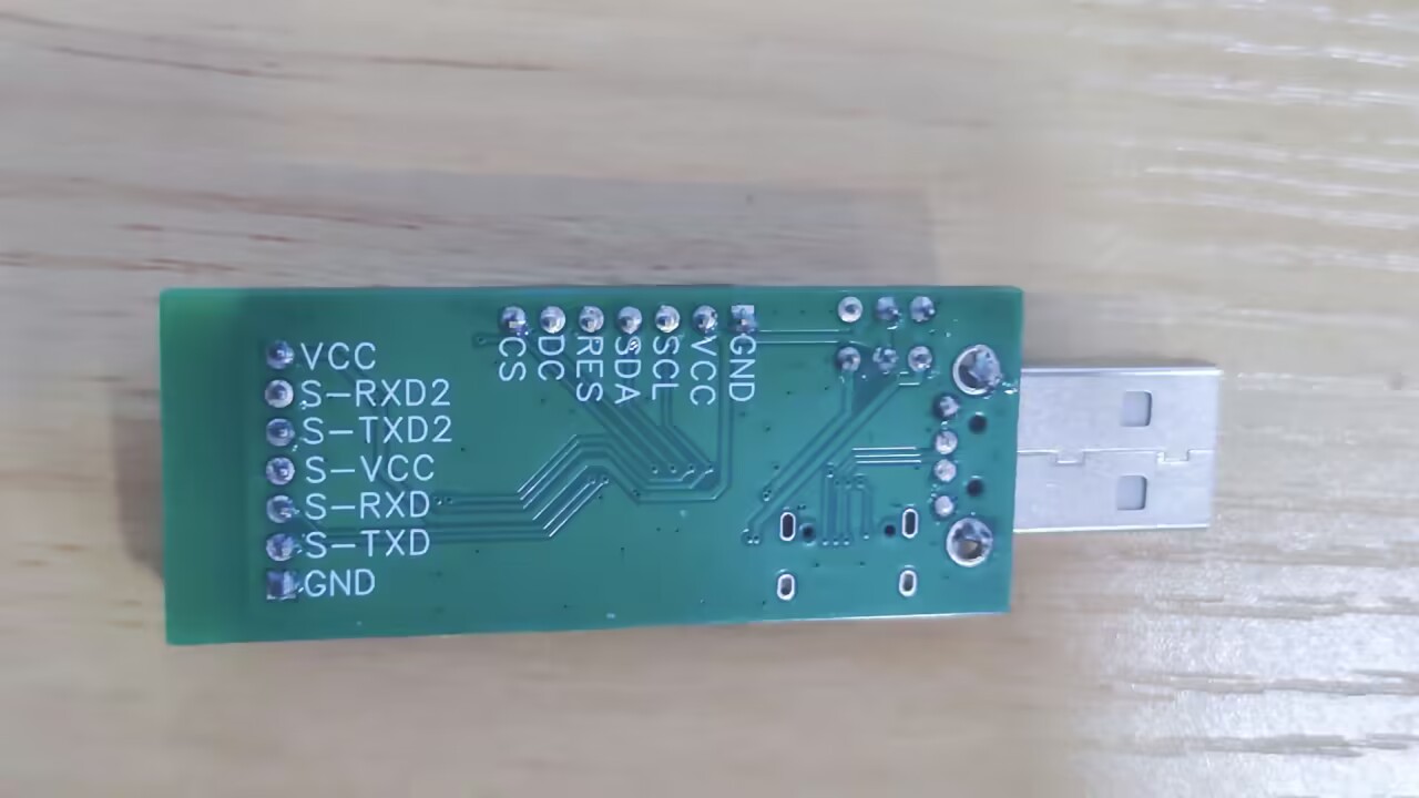
and includes an OLED display interface, supporting both 4-wire I2C and 7-wire SPI interfaces.
It also features a program update/download button, allowing program updates without disconnecting the USB cable.
Download
the STC-ISP software. The
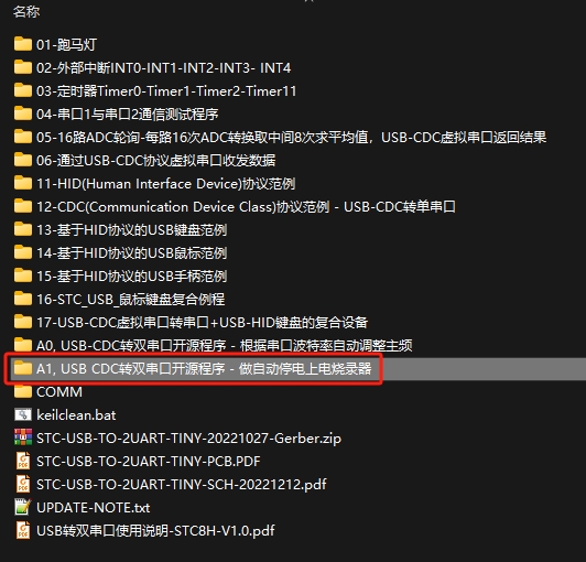
source code for this USB to dual serial port learning board
is available
on the official website: www.stcai.com. Download the compiled source code for the software tools/core function experimental board. [

Source code
for the USB to dual serial port learning board/A1, USB CDC to dual serial port open source program - for automatic power-off and power-on programmer] The program obtains the burning file stc_usb_2ser.hex.
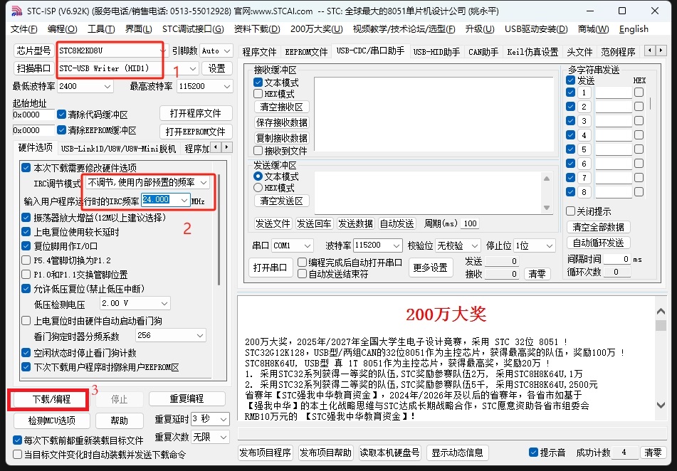
Using STC-ISP, download the program to the chip.
Insert the small board into the computer's USB port, press and hold the [Download] button, then press and quickly release the [PowerOff] button, and then release the [Download] button again. Open the ISP software; it will recognize a HID device. Select the chip model: stc8h2k08u, internal 24MHz frequency. Open the stc_usb_2ser.hex program and click the [Download] button to download the program.
Verification:
Remove the small board from the USB port and insert it into the computer's USB port. You should see two serial ports appear on the computer, indicating normal operation.

(Image of the board's appearance)
PDF_STC's Simplest USB to Dual Serial Port Converter.zip
Altium_STC Minimal USB to Dual Serial Port Converter.zip
PADS_STC Simplest USB to Dual Serial Port Converter.zip
BOM_STC Minimal USB to Dual Serial Port Converter.xlsx
91304
(Verified) Power supply board based on SW3518S chip
The functional verification board for the SW3518S chip has been verified.
Precautions:
1. The SW3518S essentially integrates a buck converter (as stated in the datasheet). According to numerous user tests, it's best to connect it to a 24V power supply. However, it can also be used with voltages below 24V, such as 20V. Currently, there are fewer experiments with this; I will test it more when I have time.
2. When modifying the device, be sure to select the correct voltage rating for each component!
3. The SW3518S chip generates a significant amount of heat during use. I recommend, like I did, using two heatsinks.
ISmartWare-SW3518S.pdf
SW3518S.html
PDF_(Verified) Power Board Based on SW3518S Chip.zip
Altium (verified) power board based on SW3518S chip.zip
PADS (Verified) Power Board Based on SW3518S Chip.zip
BOM (Verified) Power Board Based on SW3518S Chip.xlsx
91305
Automatic screen ambient lighting based on Anxinco RD03E
Using the RD03E radar module from Anxinco as a sensor, the system detects the presence of a person in front of the screen and automatically switches the screen's ambient lighting mode based on that presence.
The project
utilizes the Axiomtek RD03E radar module as a sensor to detect the presence of a human body in front of a screen and automatically switch the screen's ambient lighting mode accordingly.
The project began with a radar module I received for free at an Axiomtek event. The task was to complete a practical project using the module. Due to the recently set up, simple table and insufficient ambient lighting, the screen was very glaring, causing discomfort to the corpse's eyes after prolonged sitting. Therefore, the idea arose to create an ambient lighting effect to provide backlighting and improve the corpse's comfort.
Because the project is relatively simple, requiring few external connections, and the radar module itself is quite small, all external connections were soldered instead of plug-in interfaces to maintain a compact size for the casing. So far, there have been no breakages during multiple tests. The plan is to add silicone rubber for further fixation when installing the casing.
For details on the implementation process and some software debugging process, please refer to the posts on the Axico forum:
【Radar Lighting Control】Axico Rd-03E+ Ambient Light (ESP32 S3)
【Radar Lighting Control】Axico Rd-03E+ Ambient Light (ESP-02 PCB Version)
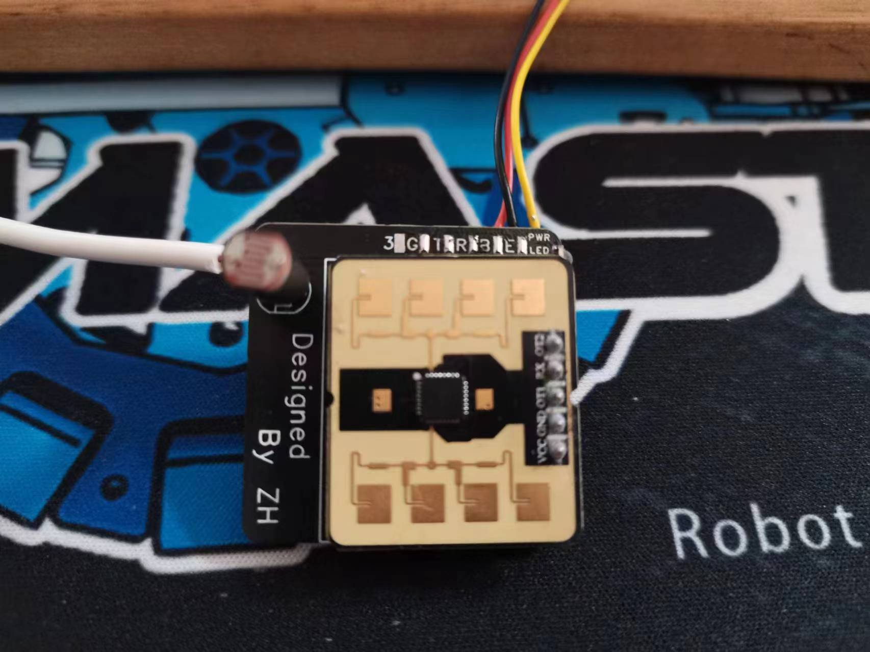
The current physical prototype
does not have a casing because I don't go back to school often and don't need the lab printer. I will update it later when I design it. For now, I'll use a dental floss box to house it (a friend in the group said it makes radar detection more accurate).
The following three pictures show the front and back of the PCB and the dental floss box installation diagram.


Functionality:
1. Automatically switch ambient light modes based on radar status.
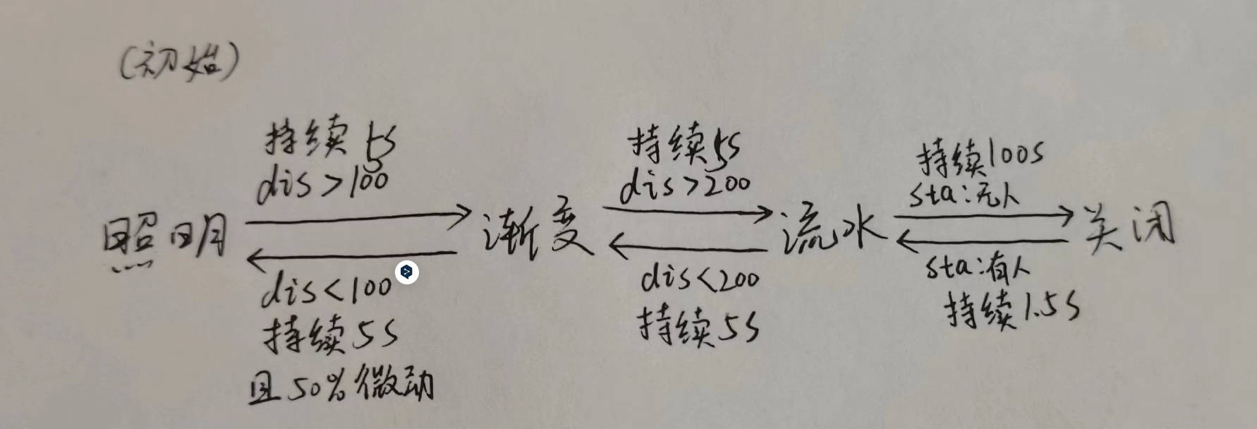
Lighting effects and switching logic:
Initialization: Enters lighting mode, i.e., a fixed warm yellow ambient light, illuminating the wall behind the screen; If someone is more than 1 meter away for 5 seconds, switches to gradient mode, where the same color of the light strip cycles on the RGB color wheel; If someone is more than 2 meters away for 5 seconds, switches to flowing light mode, where the light strip displays a flowing light effect; If no one is around for 100 seconds, turns off the light for slight energy saving; If someone is present for 1.5 seconds, switches back to flowing light; If someone is more than 2 meters away for 5 seconds, switches to gradient mode; If someone is within 1 meter for 5 seconds and is in a micro-movement state for 50% of the time, switches back to lighting mode;
2. Detects ambient light and adjusts ambient light brightness
; 3. Connects to an MQTT server, uploads ambient light to the MQTT server and HA; Receives control commands from HA via MQTT to manually adjust ambient light brightness, mode, and on/off status.
Project progress
3.12 Completed the experimental version based on the LCSC ESP32 S3 development board, completing basic functions.
3.22 After the graduation project defense, completed the schematic and PCB design of the current version.
4.2 Updated the Radar 9600 baud rate firmware, completed the software porting of the ESP02 version, completed functions 1 and 2 , and added MQTT
as planned . Completed function 3 (after completing the graduation project demonstration video control board, located on the right side of the monitor stand with the red light ). Upon power-on, the default lighting mode switches to gradient mode after approximately 15 seconds (green light off) , then switches to flowing light mode after approximately 45 seconds, switches back to gradient mode after approximately 1 minute and 22 seconds, and switches back to lighting mode after approximately 1 minute and 40 seconds (green light on).
ed2e078b34cce289c5399dbdc910794a.mp4
radarlight02.zip
PDF_Automatic Screen Ambient Light Based on Aisinco RD03E.zip
Altium_Automatic Screen Ambient Light Based on Anxinco RD03E.zip
PADS_Automatic Screen Ambient Light Based on Anxinco RD03E.zip
BOM_Automatic Screen Ambient Light Based on Anxinco RD03E.xlsx
91306
Taishan relies on BGM audio system modification board
This project involves using PCB design to modify a Tarzan-style toy, adding background music (BGM) speakers. It emits different "chicken sounds" on four different occasions: power on, power off, plugged in, and unplugged, giving the Tarzan-style chicken character the ability to sing, dance, rap, and play basketball.
"Taishan Kao" Electric Toy Audio Modification
: I. Basic Information
"Taishan Kao" is a popular toy among many fans, but unfortunately, it lacks its own background music (BGM). I previously modified it to play Chicken Bro's exclusive BGM during movement. A modification video was posted on Bilibili: Modifying "Taishan Kao"—Giving an Electric Toy its Own BGM.
This modification differs from previous ones, using a circuit board. Inspired by netizens, I added corresponding "Chicken Sounds" for different operating states, totaling four states:
1. Plug in charger—"Wow, it really is you!"
2. Unplug charger or turn off switch—"Isn't your Kun Bro awesome?"
3. Turn on switch—Initiation theme song, and the toy starts moving.
4. Turn on switch while charging—"What are you doing~ Ouch~" (Reminding you not to start while charging)
The above four states are controlled by the RS2255XN analog switch control chip.
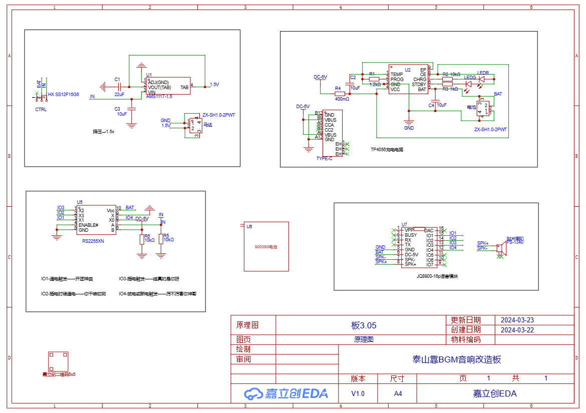
II. The basic schematic diagram
consists of 5 parts: step-down module, charging module, voice control module, battery, and voice playback module.
III. PCB Design
The design follows these principles:
1. Utilize existing space and components as much as possible, and minimize destructive modifications;
2. Save money and make soldering easier (use 0805 capacitors, resistors, etc.);
3. Must include GEIGIE elements ;

4. 0.8mm thick FPC board is recommended, as thicker boards will affect installation.
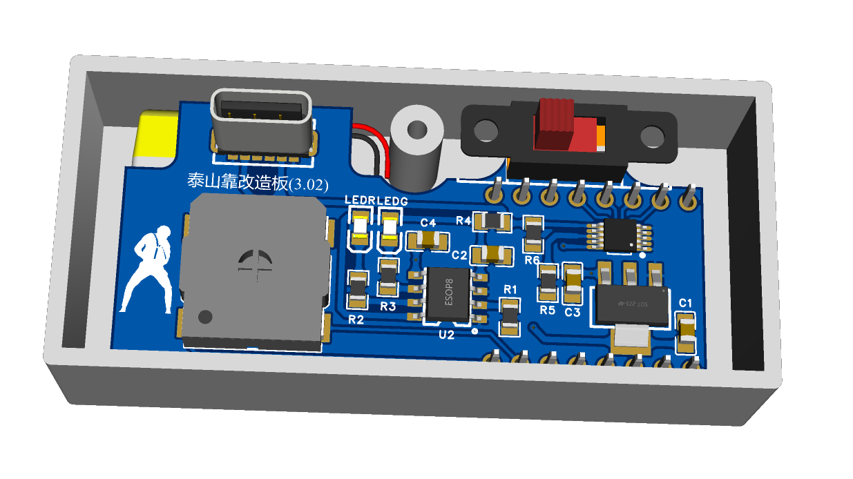
Front and
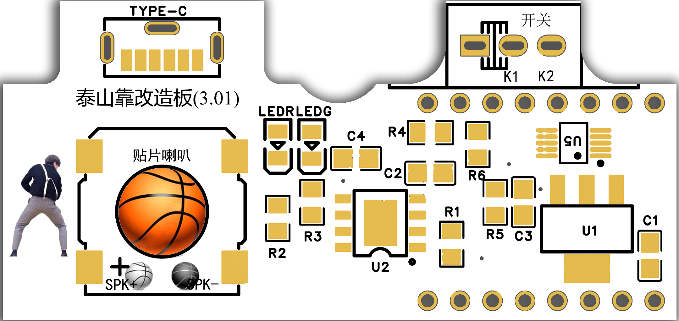
back

IV. Shell Design
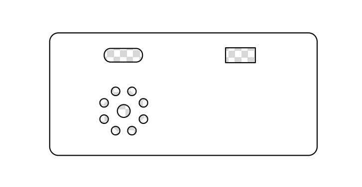
Since the Taishan Kao (a type of cardboard box) already has a shell, you need to drill holes in the back cover yourself. Therefore, two options are provided here.
(I) Do it yourself. Drilling holes in the existing back cover requires strong hands-on skills, but the advantage is that it saves money. Here I provide a drilling positioning file, which can be printed out and pasted onto the back cover for easy drilling positioning. See Attachment 1.
(II) 3D printing. If you have plenty of money, or your hands-on skills are too poor, or you have a 3D printing voucher, you can choose 3D printing. You only need to print the back cover.
Note: Because JLCPCB's 3D design software has certain limitations compared to professional CAD software, I re-drew a 3D model of the back cover using UG, see Attachment 2. (You can also use the 3D model in JLCPCB EDA without much problem.)

V. Panel Design
Since JLCPCB provided a panel coupon, take advantage of it. Of course, you can also print the corresponding color stickers yourself.

VI. Bill of Materials and Other Notes
1. Most materials can be purchased from the LCPCB online store. For ease of soldering components, I mainly use 0805. Of course, if you want to use 0603 or others, just replace them with the same value, and you will need to modify the schematic diagram yourself.
2. For voice, I directly used the readily available JQ8900-16P voice module, which can be purchased on Taobao. The relevant configuration files are in Attachment 3 (just put the 4 decompressed files in the root directory). Of course, you can also modify the voice later (explore Attachment 4 yourself).
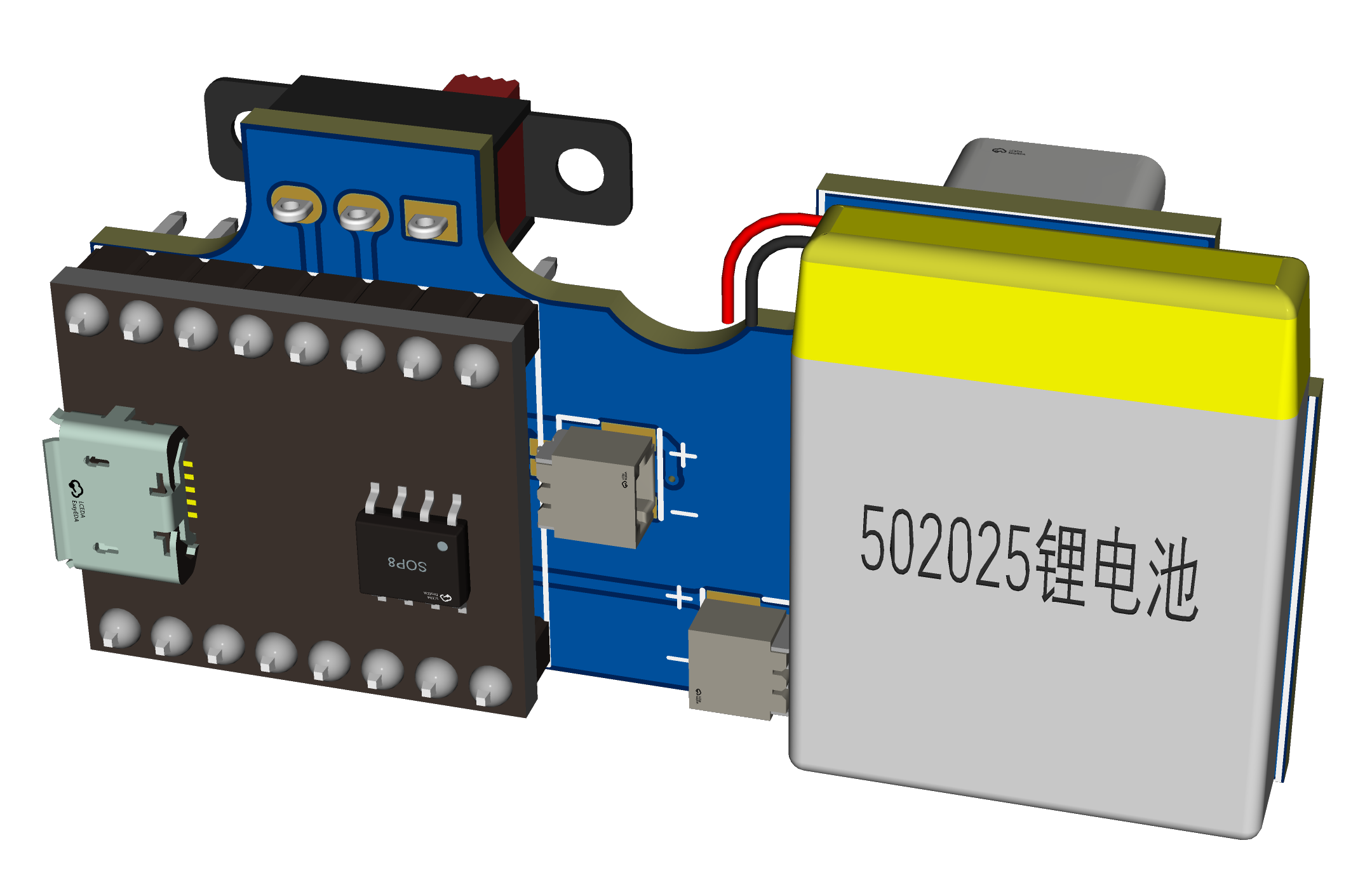
3. The motor and battery terminals are optional; you can solder the corresponding wire ends onto the large solder pads. I designed this to facilitate installation and battery replacement.
4. The slide switch is also optional; it is exactly the same as the original.
5. Ideally, a 702025 battery should be used, as its thickness fits perfectly (however, LCSC is out of stock, so a 502025 battery can be used as a substitute, requiring the bottom of the battery to be raised by 1-2mm).
VII. Assembly :
Assemble and solder as shown in the diagram, then install it into the original casing. Don't forget the motor wires; make sure to connect the corresponding wires. The simulation diagram is slightly incomplete.
Assembly is relatively simple. The tutorial has been uploaded to Bilibili: Electronic "Fool's Fun" - Taishan's Toy Speaker Modification Board Soldering and Assembly Tutorial

VIII. Results
: Enough talk, watch the video
. IX. Some Notes:
1. Due to several design changes, it differs slightly from the initial version. Some images haven't been updated yet, so please pay close attention.
2. The charging module references Animal's open-source project | Tp4056 Charging Module (Compatible with Perforated Boards) - LCSC EDA Open Source Hardware Platform (oshwhub.com). Thank you!
3. This design is open-source for learning and exchange; commercial use is prohibited without permission.
4. The finished products will be available on Xianyu (a second-hand marketplace). If you're interested, please visit https://m.tb.cn/h.5CoC7Qa?tk=iiNNWoOzEUH.
5. To expedite the open-source release, I haven't had time to print the back cover and panel yet. I'll add them later if needed.
Attachment 1_Drilling Positioning Sticker.pdf
Attachment 2_Back Cover.stp
Attachment 3_Voice Module Configuration File.rar
Attachment 4_JQ8900-16P Voice Module Data Package V1.1.zip
March 23 (1)_x264.mp4
PDF_Taishan Lean BGM Audio System Modification Board.zip
Altium_Taishan Lean BGM Audio Modification Board.zip
PADS_Taishan Lean BGM Audio Modification Board.zip
91307
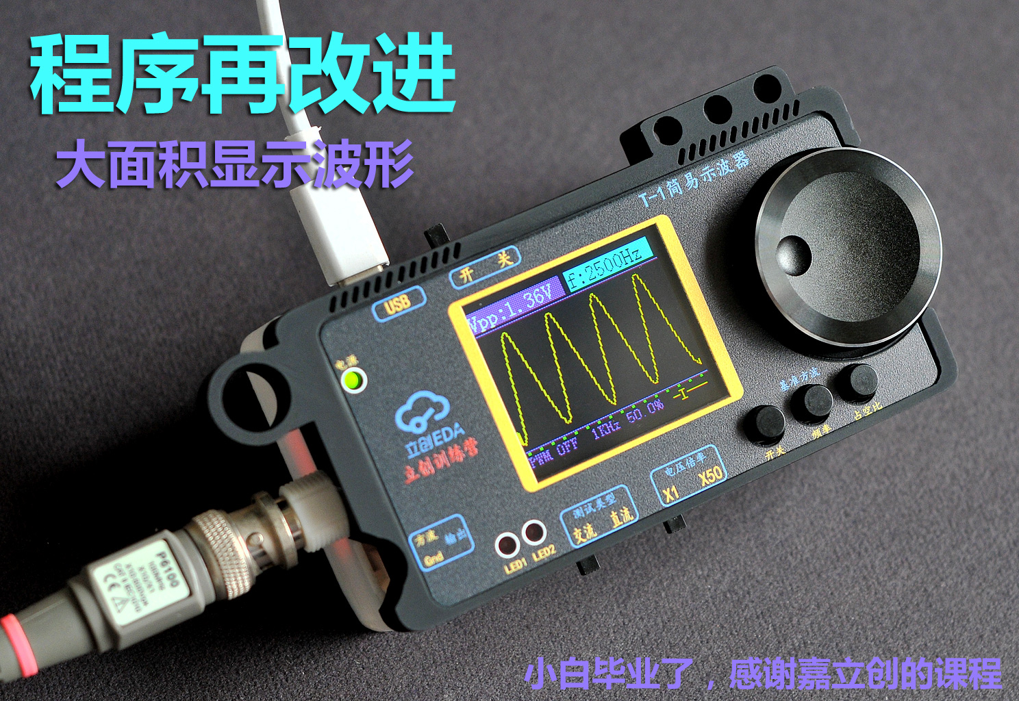
#Training Camp# Simple Oscilloscope [Open Source File Download] 9.9 RMB GD32 Microcontroller STM32 Microcontroller 1.8-inch 7735 Screen - 632263W
Cost: The entire circuit costs around 30 yuan [a simple oscilloscope based on a 9.9 yuan GD32 microcontroller, a 1.8-inch 7735 screen costs 7-11 yuan, PCB provided free of charge by JLCPCB, and other parts totaling 10 yuan]. If the casing uses LCPCB blind boxes (X resin), it costs around 22 yuan.
In March 2024
, I participated in the LCSC training camp, learning the principles of a simple oscilloscope, PCB fabrication, GD32 microcontroller programming experiments, and how to design the casing for LCSC EDA. It was my first time using LCSC EDA to design casings and panels, and I was truly impressed by its power, ease of learning, and convenience. Crucially, LCSC has promised to provide LCSC EDA permanently free of charge; LCSC's contributions to the nation are immeasurable, and I deeply admire them.
As an audiophile who frequently works on audio circuits, I already own an oscilloscope, but it's quite bulky. For a long time, I've wanted a mini oscilloscope—not requiring high precision or high frequency measurements, just something convenient for checking circuit waveforms. This training camp was perfect for me.
After learning, I modified the layout, prioritizing practicality and ease of use: the left hand operates the probe (input is on the left), and the right hand operates all function keys and knobs (most function keys are located within right-hand reach), conforming to my usual usage habits.
On the software side, I'm a complete beginner with the GD32 microcontroller (I had never even heard of it before joining the training camp). I'm currently learning programming, referencing the default program from the training camp, replicating and improving it. The improved version is available for download in the attachment. (Links to the official tutorial videos and complete materials are below; I won't repeat the principles and circuits here.)
Regarding the casing, I was surprised how convenient it was to design the casing using "LCSC EDA" (I've never learned any other 3D modeling software, always considering it a huge hurdle). Because this PCB design uses connectors for the microcontroller and display, the overall thickness is relatively high. This was my first time designing a casing, so the focus was on familiarizing myself with the software's functions and the order-making process. Next time, I'll design a second version with an integrated circuit board, where the casing can be made ultra-thin.

The actual product is more refined and attractive than the pictures. I often play with it on my desk. Aside from its functionality, I use it as a stress-relieving toy (like a ZIP lighter)


.
This was my first time attending LCSC's training camp, and I learned a lot. I felt very refreshed and corrected my bad habits when doing PCB design. I used to think that LCSC EDA was just more convenient than Protel, but now I know that in addition to being easy to use for PCB design, LCSC EDA can also be used to make 3D shells and product panels. It's a one-stop shop for design and production, and the entire product can be directly output. I went through the entire process, thanks to JLCPCB, I'm awesome!
Official materials for this training camp: (Downloadable files below include: official documents and my own work after learning)
Oscilloscope Project Documentation https://www.yuque.com/wldz/jlceda/dso?singleDoc
Hardware Design Recordings https://www.bilibili.com/video/BV13x4y1k7mk/?spm_id_from=333.999.0.0
Software Design Recordings https://www.bilibili.com/video/BV1kw4m1o73g/?spm_id_from=333.788
Also, because I registered for the training camp late, the QQ group was full, and the official website videos were also full due to the large number of participants. So I was essentially adrift and couldn't see the group discussions, which was a bit of a disappointment. Thankfully, the training camp provided very comprehensive online materials and learning videos. So I can confidently tell anyone wanting to replicate this project: don't hesitate, come and replicate it! The official materials are very comprehensive, and you'll learn a lot.
The actual costs have been explained in the Bilibili videos; there are four videos on Bilibili:
http://bilibili.com/video/BV1jJ4m1578k/?spm_id_from=333.999.0.0&vd_source=aa5025be82f5969b7242b0126842d2f5
https://www.bilibili.com/video/BV1ZC41157bk/?vd_source=aa5025be82f5969b7242b0126842d2f5 From
another perspective, JLCPCB provided manpower and resources, designing and producing circuit products and courses that we can learn from. I don't know the time the teachers spent in the initial preparation phase, but just from the start of the course to graduation, managing and answering student questions took more than a month. Thank you to all the teachers for your hard work! Over 2,000 students submitted assignments .
If we assume 2,000 students, and JLCPCB sponsored an average of 100 RMB per person, then over 200,000 RMB would have been given to us for free (and this is just one training camp session). This is the first time we've encountered such a wonderful company. Thank you, JLCPCB, from the bottom of my heart! I hope JLCPCB grows stronger and stronger!!
Bilibili:
http://bilibili.com/video/BV1jJ4m1578k/?spm_id_from=333.999.0.0&vd_source=aa5025be82f5969b7242b0126842d2f5
https://www.bilibili.com/video/BV1ZC41157bk/?vd_source=aa5025be82f5969b7242b0126842d2f5
There are 3 videos below + 4 videos on Bilibili (This page limits playback to 3 videos directly; there are 2 more unique videos on Bilibili).
GD32 microcontroller writing tool.rar
HEX file of the program.rar
Program source file.rar
Osc4gai3KET Full Screen Display - Modified Encoder Program - HEX File.rar
Program modified to full-screen waveform.mp4
New Program Instructions.mp4
Limit Frequency Test.mp4
PDF_#Training Camp# Simple Oscilloscope [Open Source File Download] 9.9 Yuan GD32 Microcontroller STM32 Microcontroller 1.8-inch 7735 Screen - 632263W.zip
Altium_#Training Camp# Simple Oscilloscope [Open Source File Download] 9.9 Yuan GD32 Microcontroller STM32 Microcontroller 1.8-inch 7735 Screen - 632263W.zip
PADS #Training Camp# Simple Oscilloscope [Open Source File Download] 9.9 Yuan GD32 Microcontroller STM32 Microcontroller 1.8-inch 7735 Screen - 632263W.zip
BOM_#Training Camp# Simple Oscilloscope [Open Source File Download] 9.9 Yuan GD32 Microcontroller STM32 Microcontroller 1.8-inch 7735 Screen - 632263W.xlsx
91308
electronic


 京公网安备 11010802033920号

 162-40-764-30-180000


