Project Introduction: This project uses an STM32 series microcontroller as the control core to design a simple dual-channel digital oscilloscope and waveform generator. It uses a 3.5-inch TFT LCD display and an oscilloscope probe to detect signal waveforms. The waveform generator circuit can output common waveforms such as sine waves, triangle waves, and square waves.
Main Functions:
The system uses an STM32F103CVT6 as the main controller. The 3.5-inch TFT display shows the main waveform parameters. Through independent buttons, an EC11 rotary encoder, and a BNC20 oscilloscope probe, it can output common waveforms such as sine waves, square waves, and triangle waves, as well as SinC or other custom waveforms, achieving arbitrary waveform output. Waveform parameters can be generated using Matlab software.
I. Circuit Principle Analysis:
A digital oscilloscope is an instrument used to display electrical signal waveforms. It mainly consists of analog front-end processing circuits, microcontroller circuits, power supply circuits, control circuits, etc. Since this project is an introductory project for oscilloscopes, some core circuits were selected in the circuit design, mainly including the following circuits:
(1) Analog front-end processing circuit: responsible for processing the input detection analog signal and then giving it to the microcontroller for recognition. It is the core of the whole circuit.
(2) Waveform signal generation circuit: responsible for processing the microcontroller output signal and outputting common waveforms such as sine wave, triangle wave, and square wave. It is the core of the whole circuit.
(3) Power supply circuit: responsible for providing positive and negative power to the operational amplifier and power to the system. It is the basis for ensuring the normal operation of the circuit.
(4) Microcontroller circuit: provides the control core for the system and is responsible for the acquisition, processing and output of the input signal.
(5) Human-computer interaction circuit: used to control the functions of the oscilloscope, including buttons, knobs, display screen and other input and output interfaces, providing the foundation for the development of oscilloscope functions.
1. Analog front-end processing circuit
from left to right is an inverting proportional operational amplifier circuit, a dual diode BAT54S voltage clamping circuit, an adder, and an inverting proportional operational amplifier circuit.
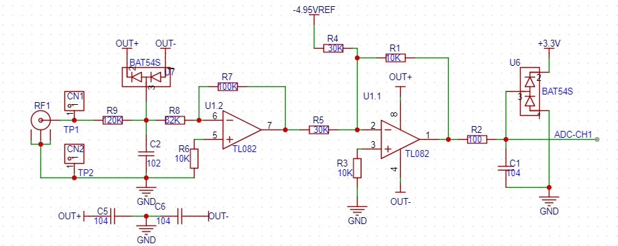
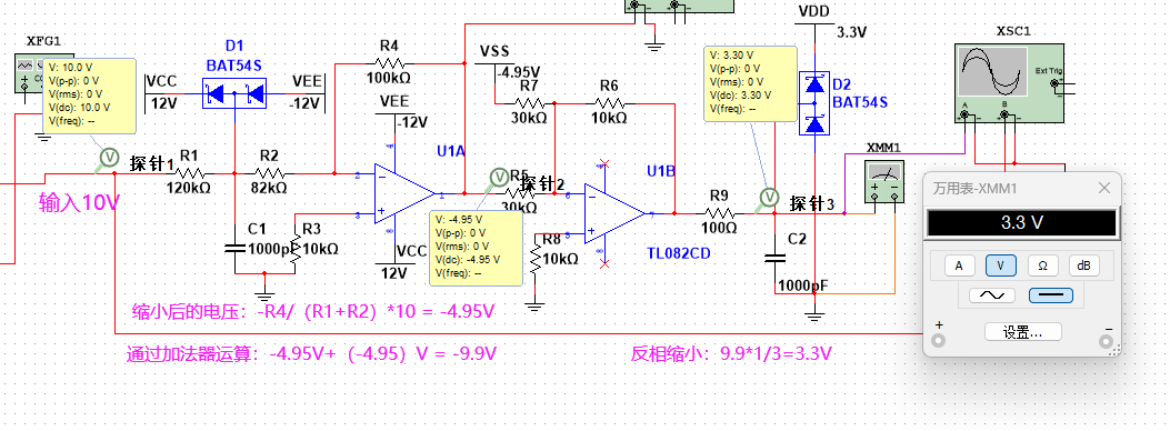
We analyze from input to output: The input acquisition part uses an inverting proportional operational amplifier circuit to reduce (about) 1/2, enters the adder circuit, and then reduces it by 1/3 before passing through the inverting proportional operational amplifier to the microcontroller circuit for acquisition. The following is an analysis and calculation process with an input of 10V:
2. Signal generation
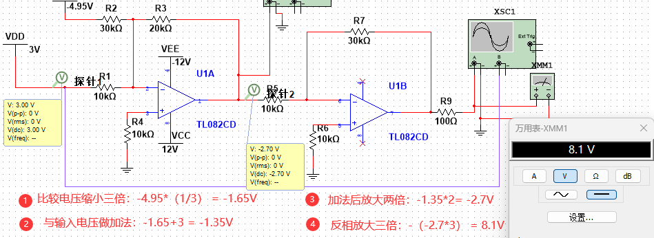
circuit implementation: An inverting proportional operational amplifier circuit is used to reduce the output voltage by 3 times, after passing through the adder, it is amplified by 2 times, and then amplified by 3 times by an inverting proportional operational amplifier circuit to obtain the final output voltage value.
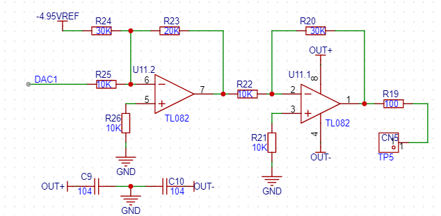
The following is the analysis process:
Note: Here, 1.65V is taken as the zero point, that is, when the output voltage is less than 1.65V, it is a negative voltage. This is something to pay attention to when writing the program.
3. Power supply circuit
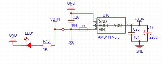
(1) +5V and +3.3V power supply circuit
The +5V and +3.3V power supply circuits in this project use MP2359 and AMS1117-3.3 chips.
MP2359 is a single-chip buck switching converter with built-in power MOSFET. It provides a peak output current of 1.2A over a wide input range, exhibiting excellent load and linear regulation performance. The current control mode offers fast transient response and makes the loop easier to stabilize.
The MP2359 operates from 4.5V to 24V with a wide input voltage range and an adjustable output range of 0.81V to 15V.
The design references the MP2359 datasheet (official English version) for a 12V to 5V voltage regulation. The datasheet provides a classic example of implementing 12V-5V buck operation and its peripheral circuit design. Here, I added a switch control for external power input when the DIP switch is on.

The AMS1117-3.3 is a 3.3V forward low-dropout regulator suitable for high-efficiency linear regulators, switching power supply regulators, battery chargers, active small computer system interface terminals, and power management batteries for laptop power supplies.
AMS1117-3.3 Output voltage range: 3.201 V~3.399 V; accuracy: 1%
. From left to right, they are input, ground, and output. After the 12V is regulated to 5V, VBTN is connected to the chip input +5V network. In addition, an F1 self-resetting fuse is added for overcurrent protection, and C25 and U17 are output filter capacitors used to suppress self-oscillation. If these two capacitors are not connected, the output of the linear regulator will usually be an oscillating waveform.
(2) Positive and negative power supply circuits
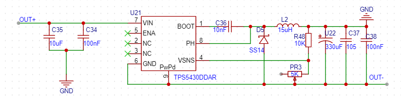
1. ±12V power supply circuit (recommended, used in this project test)
The ±12V power supply circuit in this project uses the TPS5430 chip. The TPS5430 is a high output current PWM converter that integrates a low resistance, high-side N-channel MOSFET. The substrate with the listed features also includes a high-performance voltage error amplifier, an undervoltage lockout circuit (to prevent startup before the input voltage reaches 5.5V), an internally set slow-start circuit (to limit inrush current), and a voltage feedforward circuit.
The circuit design uses a combination of a large and a small capacitor for filtering, reducing power supply ripple while achieving better transient response.
The OUT+ power input is 12V. The output voltage can be adjusted by adjusting the adjustable resistor PR3. The negative voltage Vout-=((R48+PR3)*1.221)/PR3.
D5 and L2 are the inductor and freewheeling diode in the BUCK-BOOST reverse voltage circuit topology.
2. ±5 power supply circuit (not recommended for use after testing, not used in this project)
The ±5 power supply circuit uses the SGM3204 charge pump chip, a switched capacitor voltage converter, with a maximum output of 200mA, and can be used for operational amplifier amplification, filtering, and other circuits.
Input voltage: 1.4V~5.5V Output voltage: -5.5V~-1.4V

(3) Reference voltage source
When using ±12V as input in this project, the voltage reference chip is TL431AIDBZR. This device is a three-terminal adjustable parallel regulator that can meet the specified thermal stability within the applicable automotive, commercial and military temperature ranges. The output voltage can be set to any value between Vref (approximately 2.5V) and 36V using two external resistors. Note: The value of Vin must ensure that IKA is between 1-100mA, i.e., 1mA.
An adjustable resistor is added to this circuit design to adjust the output voltage. The resistance value calculated by simulation is: -Vout=(1+(4.7+0.54)k/(4.7+0.46)k)*2.5 = -4.95V.

When the project uses ±5V as input, the voltage reference circuit is as follows (it is not recommended to use after testing, R47 should not be soldered):

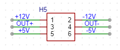
(4) Test power selection circuit:
Use jumper caps to select the required power gate. This project uses ±12V for testing.
4. Microcontroller circuit
The microcontroller control core is STMicroelectronics' STM32F1 series mainstream MCU - STM32F103VCT6. The MCU uses a Cortex-M3 core, with a maximum CPU speed of 72 MHz, 256KB Flash, various control peripherals, a USB full-speed interface, and CAN.
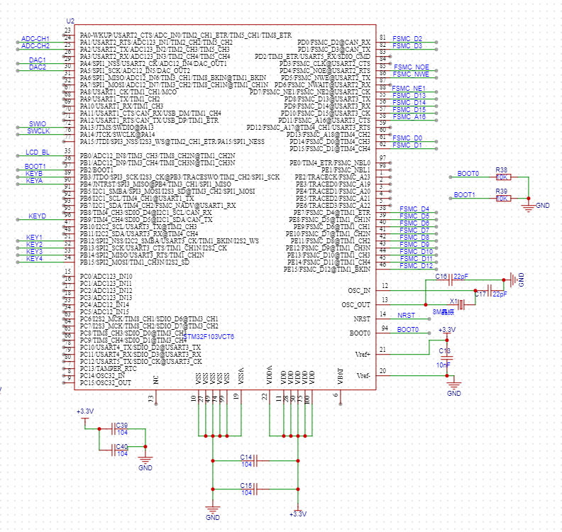
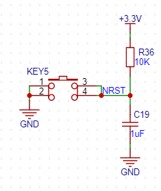
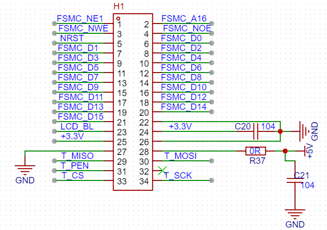
Reset circuit and STLINK debugging circuit
5. Human-machine interaction circuit
(1) 3.5-inch TFT LCD screen
The information display part of this design uses a 3.5-inch TFTLCD module LCD screen from Zhengdian Atom (I got it for free~~~). The screen has a resolution of 480*320, a wide viewing angle, and a delicate and non-glaring display. It uses a 16-bit 80 parallel port. Of course, it can also be replaced with a cheaper SPI screen. Since I have the project code, I will not use other displays here for convenience.
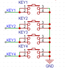
(2) The key input detection circuit
uses four independent keys to control the system. One side of each key is directly grounded, and the other side is connected to the microcontroller pin. When the microcontroller pin detects that a key is pressed, it is directly connected to GND. The microcontroller receives the grounding signal from the key and then performs the corresponding function. To save hardware costs, debouncing can be introduced in the software design to avoid false triggering when the mechanical key bounces.
(3) Rotary encoder circuit The
rotary encoder is a special type of key. The EC11 rotary encoder used in this project has five pins. Pins D and E are similar to ordinary key pins. They are turned on when pressed and turned off when released. The remaining three pins A, B, and C are used to detect the rotation direction of the knob. Pin C is the common terminal and can be directly grounded.
When the rotary encoder is in operation, there is a phase difference between the A and B signal pins. That is, the signal of one pin changes and then the signal of the other pin changes. The two pins do not change at the same time. By detecting which pin changes first, it can be determined whether it is a forward or reverse rotation function.

6. Power Supply Soldering Test

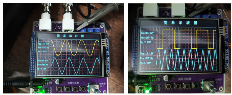
II. Experimental Phenomena:
Detecting sine waves, triangle waves, and square waves emitted by the signal generation circuit.
III. Operating Instructions
: Buttons from left to right: Increase sine wave frequency, decrease sine wave frequency, increase triangle wave frequency, decrease triangle wave frequency.
Encoder: Clockwise knob: Amplify the waveform; Counterclockwise knob: Reduce the waveform.


 京公网安备 11010802033920号

 12159AGK-13CECC


