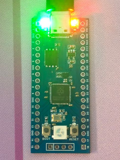
It uses a Type-C interface, has 16MB of onboard Flash memory, a power indicator, an LED connected to GPIO25 (the default pin in the Blink example), and an RGB LED. It has been verified through power-on and program testing.
Design reference: hardware-design-with-rp2350
PDF_RP2350 Development Board Pi Pico 2.zip
Altium_RP2350 development board pico 2.zip
PADS_RP2350 development board pi pico 2.zip
BOM_RP2350 development board pi pico 2.xlsx
93129
#Training Camp#Digital Oscilloscope
Simple Digital Oscilloscope
1. Description: A simple oscilloscope/signal generator, using a GD32 microcontroller as the main controller with on-chip ADC sampling. It also features an OLED screen and three control buttons for convenient display and operation.
2. Hardware Design:
1. Microcontroller: Uses a GD32 microcontroller as the main controller, providing sufficient processing power and rich library function support. 2. Analog Input: Receives external signals using analog input pins and converts analog signals to digital signals via an ADC (Analog-to-Digital Converter). 3. LCD Display: Uses a 128x64 pixel LCD screen for real-time waveform display. 4. Power Supply: Powered via USB, with an LDO circuit converting the power supply to the operating voltage required by the microcontroller and LCD.
3. Software Design:
1. Signal Acquisition: Writes GD32 standard library code, configures analog input pins, and uses built-in ADC library functions to sample and convert analog signals. 2. Waveform Display: Uses graphics library functions to draw waveform images on the LCD screen. Basic graphics drawing algorithms can be used. 3. Interface Design: Design a simple and intuitive user interface, allowing users to control the oscilloscope's operation via buttons or knobs, such as selecting the sampling frequency and adjusting the display range. 4. Signal Processing: Signal processing functions, such as filtering, peak detection, and spectrum analysis, can be added to enhance the oscilloscope's capabilities.
WeChat image_20240814190651.jpg
WeChat image_20240814190659.jpg
PDF_#Training Camp#Digital Oscilloscope.zip
Altium_#Training Camp#Digital Oscilloscope.zip
PADS_#Training Camp#Digital Oscilloscope.zip
BOM_#Training Camp#Digital Oscilloscope.xlsx
93130
DAPLINK Downloader
DAPLink Downloader based on AT32F425-F8P7
This project
uses the AT32F425-F8P7 as the main control chip, which is inexpensive and has USB functionality. An 8MHz active crystal oscillator is used onboard; note that it is active to ensure the stability of the debugger system. Other peripherals are limited to a minimum system board, resulting in a simple structure. Soldering
Precautions:
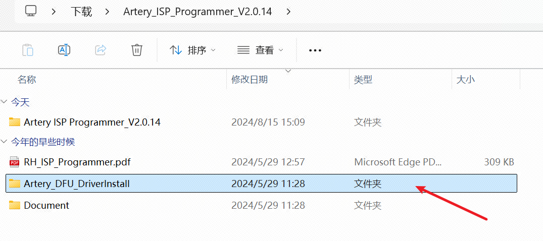
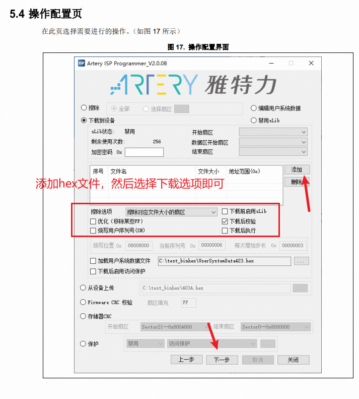
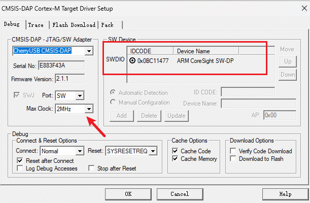
The active four-corner crystal oscillator has a specific orientation; pay close attention during soldering. The project references the open-source AT32F425 downloader from FanHuaCloud; you can download the project's program files directly from that user's Gitee link or directly using the hex file. The pinout is universal. In addition, if you want to save costs further, you can also use the internal crystal oscillator version directly. All the above information will be placed in the attachment . Note: The hex file in the attachment is for the external crystal oscillator. Programming instructions: 1. You can choose to open Keil 5, follow the corresponding support package for AT32, and then open the program file. Use another Link to connect to the GND, 3V3, SWDIO, and SWCLK pins for programming. After successful programming, it can be used as a DAPlink. This method is no different from ordinary programming, so no pictures or text descriptions are provided here. 2. Select the AT32 ISP download tool and use the serial port to burn and download hex files. After downloading the ISP tool, you need to install the driver first; simply double-click to install. Then open the ISP tool; the board is not powered on at this point. Find a CH340 serial port programmer and connect 3V3, GND, RX, and TX. Note that TX and RX are reversed. Then, press and hold the BOOT button, connect the power supply, and release it after one or two seconds. In the ISP, select UART. After successful burning, the device can now be used as a DAPlink to download programs to other devices. In Keil5 configuration , click the magic wand , select debug, and then select dap. The link should now communicate normally with the board. If it cannot communicate normally, check if the board is connected or powered on. Note that the download speed is not recommended to exceed 5MHz; too fast a speed may cause download failure. This is not a high-speed USB . In summary, you can now use it normally to burn and debug programs.


at32f425_template.hex
at32-f425_-dap-master (external crystal oscillator).zip
Project (with built-in crystal oscillator).7z
PDF_DAPLINK Downloader.zip
Altium_DAPLINK downloader.zip
PADS_DAPLINK Downloader.zip
BOM_DAPLINK Downloader.xlsx
93131
E72 CC2652P Z2M
zigbee2mqtt USB dongle
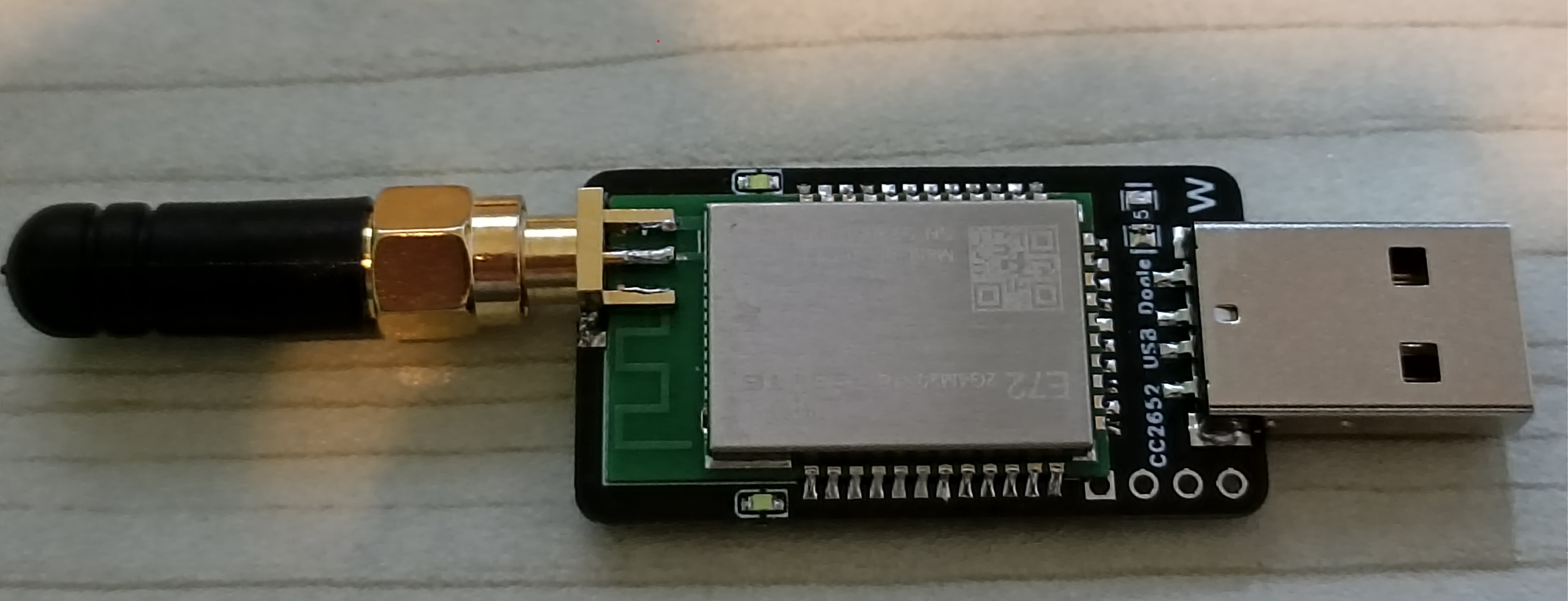
The front and
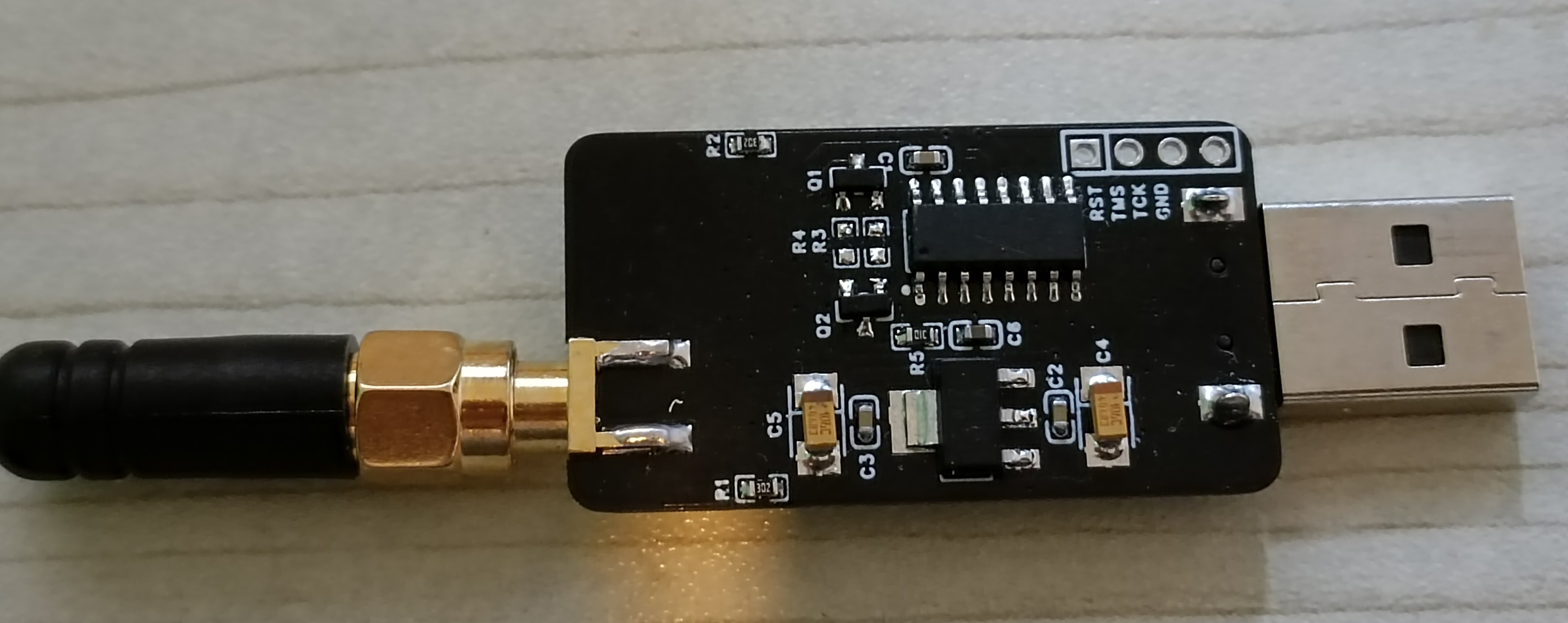
back views
show the E79 module from Ebisoft, paired with zigbee2mqtt as a Zigbee gateway. Currently, zigbee2mqtt supports over 2700 third-party devices from more than 390 vendors, making it an excellent open-source project for quickly implementing Zigbee smart home solutions. Zigbee2mqtt, combined with Home Assistant, is a must-have.
This PCB does not use foreign open-source boards; all measurements were done manually, and multiple prototypes were made to achieve the appropriate dimensions.
Important: If you want to use an antenna mount, the PCB thickness must be 0.8mm, and the ink needs to be scraped off to expose the copper for soldering, as shown in the image.
If you don't want this complicated process, you can directly use the module's onboard antenna, which has no PCB thickness requirement. (The actual test results are also acceptable.)
PS:
The green box in the schematic diagram doesn't allow soldering (I originally wanted to put two buttons, but adding a casing wouldn't be convenient), because when zigbee2mqtt starts up, it calls USB to operate RTS and DTR, causing CC2652 to enter SBL mode, resulting in a timeout error during zigbee2mqtt startup. I haven't found the cause yet; I'll check the part where Z2M calls the USB library later. If anyone solves this, please share it for reference.
The attachment is a downloaded version from GitHub, compatible with the E72 module. You can also modify the program to adapt to other modules, following the official instructions to patch it. Here's the link:
https://github.com/Koenkk/Z-Stack-firmware/tree/master/coordinator
(in Z-Stack_3.x.0)
. ---
If the E72 module isn't available, I also drew an E79 module, which can be found in the open-source marketplace. Of course, there are many other compatible open-source projects; choose according to your preference. You can also choose to DIY your own zigbee sensor; I'll put a link here, and I hope everyone will support it. https://oshwhub.com/myjuly/ji-yucc2530-dizigbee3-0-men-ci---
CC2652P_Film_20221226.zip
PDF_E72 CC2652P Z2M.zip
Altium_E72 CC2652P Z2M.zip
PADS_E72 CC2652P Z2M.zip
BOM_E72 CC2652P Z2M.xlsx
93133
LCD-BL-240805
LCD backlight driver test board
LCD backlight circuit test board with PWM dimming control pins.

PDF_LCD-BL-240805.zip
Altium_LCD-BL-240805.zip
PADS_LCD-BL-240805.zip
BOM_LCD-BL-240805.xlsx
93134
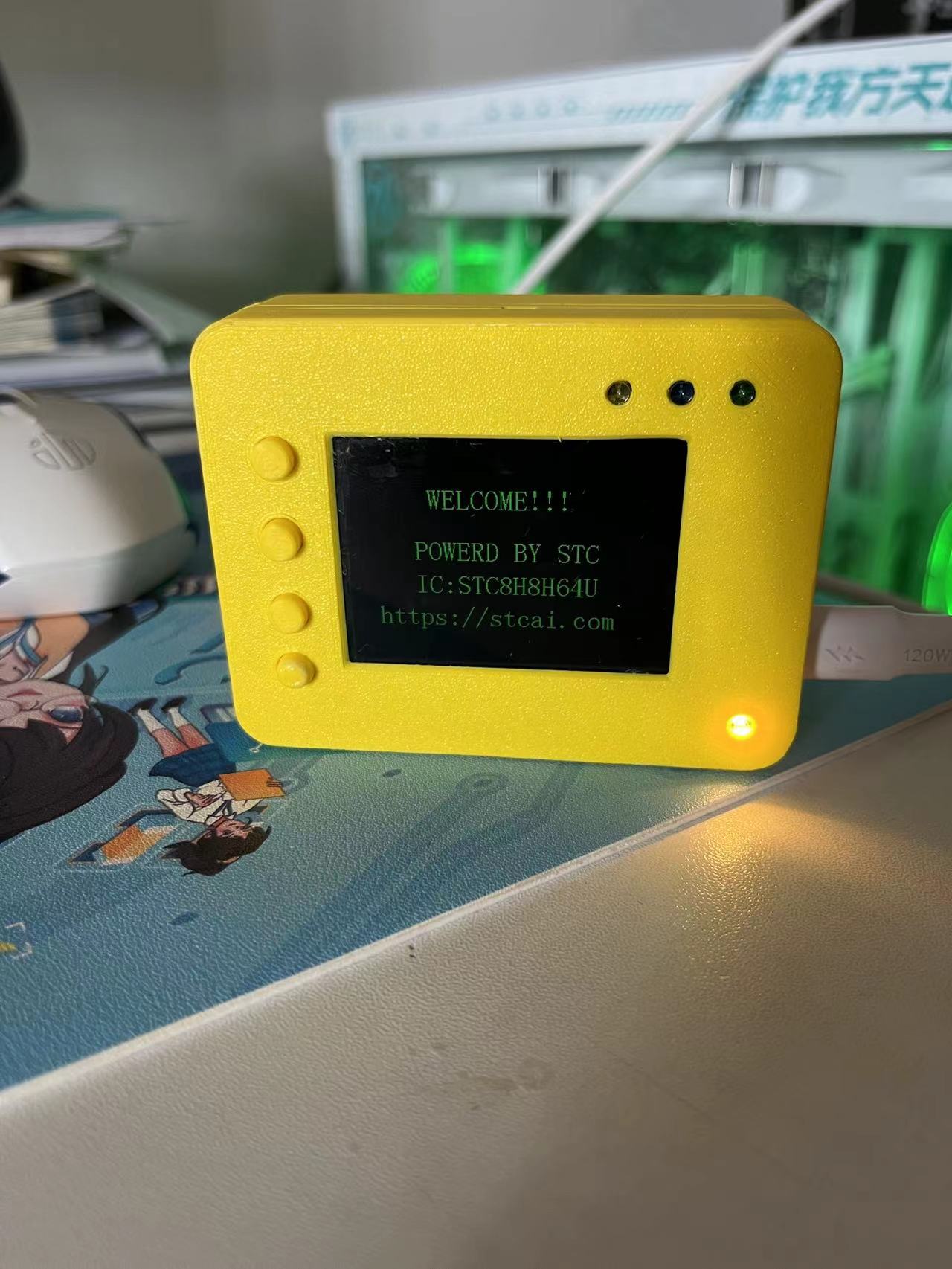
Temperature and humidity monitoring
This temperature and humidity sensor is based on the domestically developed STC 51 microcontroller. It displays information on an LCD screen, allowing for user interaction via buttons and the screen. Additionally, a voice module is included for temperature and humidity alerts, and a Bluetooth module allows for temperature and humidity data to be obtained via a mobile phone.
Peripherals used
: GPIO: for screen driver, LEDs, buttons, etc.;
UART: uses two serial ports to interact with the Bluetooth module and voice module respectively;
SPI: used to communicate with external flash memory and store fonts, etc.;
main function
buttons are used to set temperature and humidity alarm values, which
are then displayed on the LCD;
Bluetooth connects to a mobile phone, allowing users to check temperature and humidity from the comfort of their bed;
the voice module is used to alert users when temperature and humidity reach alarm values
. Additionally, this project uses battery power, and
semi-finished products such as battery charging and discharging circuits are shown.

PDF_Temperature and Humidity Monitoring.zip
Altium_Temperature and Humidity Monitoring.zip
PADS_Temperature and Humidity Monitoring.zip
BOM_Temperature and Humidity Monitoring.xlsx
93135
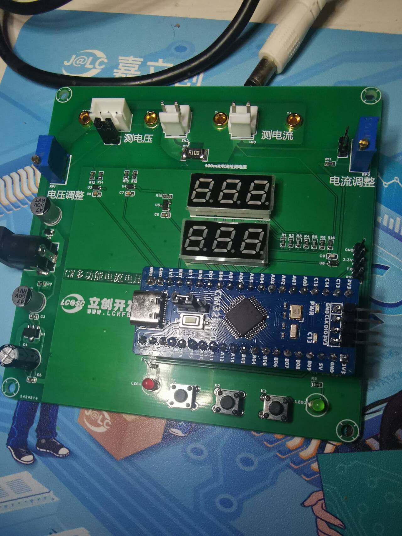
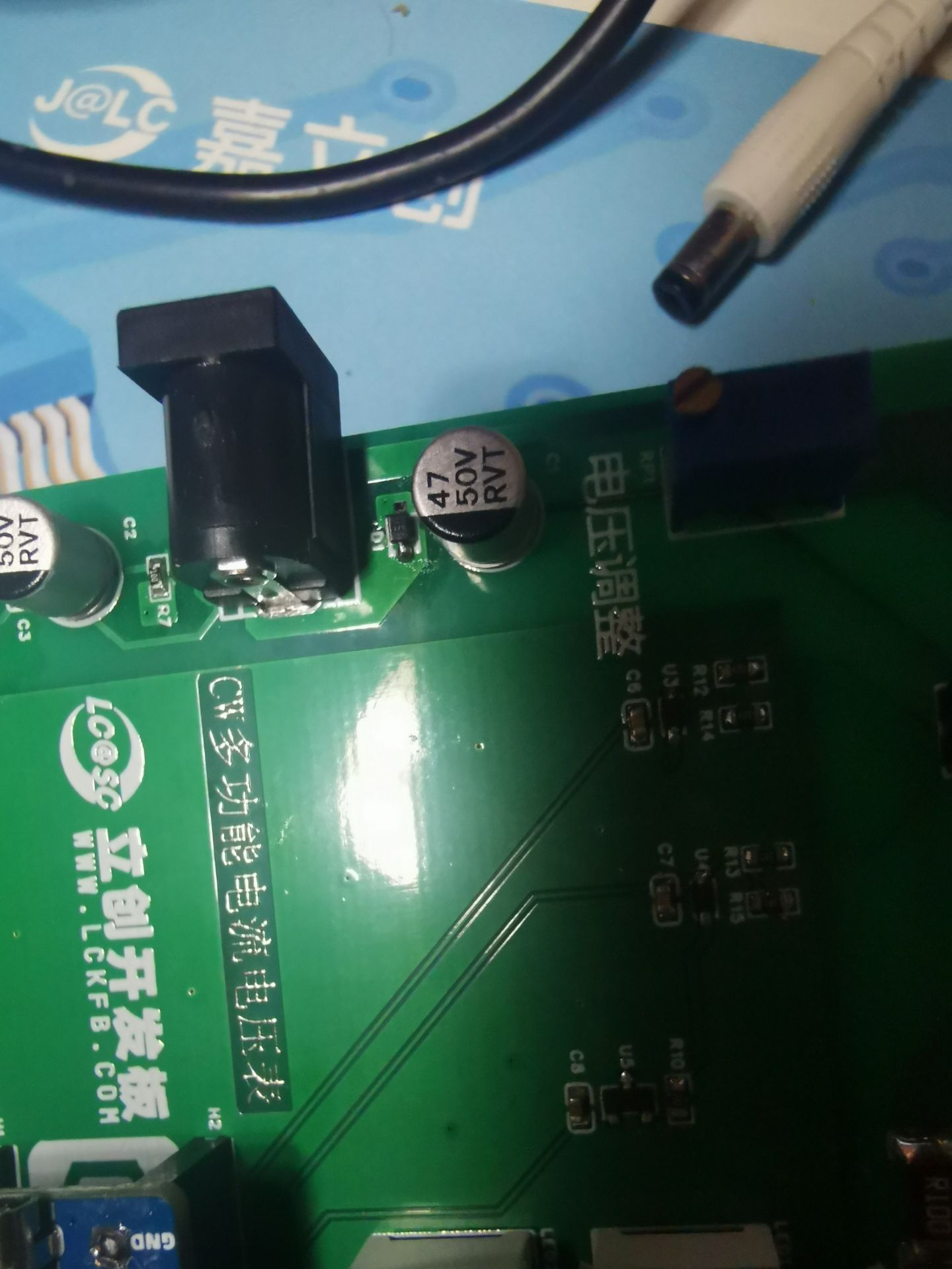
CW32 Simple Voltage and Current Meter
Based on the CW32F030C8T6 simple voltmeter and ammeter, a very useful digital voltmeter and ammeter.
I'd always heard about the high accuracy of the CW32
's ADC, but I'd never had the chance to use it. I even missed the training camp organized by the CW32 ecosystem community. Thanks to LCSC EDA and the CW32 ecosystem community for providing the 1 RMB development board and other coupons, and for organizing this training camp, they taught us how to build a voltage and current meter step-by-step.
On the hardware side
, this voltage and current meter offers two voltage division ratios for measuring voltage,
provides four sockets for comparative testing and calibration with multimeters and other measuring tools,
uses a 100 milliohm resistor for voltage sampling, calculates and measures current,
increases current routing, and supports high current input.
On the software side
, it supports switching ADC sampling pins to change ranges,
switching reference voltages to change accuracy and calibration, and
calibration to adjust measured values .
During the construction process
, I followed the teacher's schematics step-by-step, learning a lot of key technical knowledge and PCB design skills
, but I still encountered many pitfalls, including accidentally drawing the board incorrectly. After soldering, the power indicator light didn't turn on when plugged into a DC power supply, but it did work when plugged into a USB port. After much research and testing with a multimeter, I finally found the problem. I had drawn the diode at the DC power input position backwards, preventing power from flowing. I removed the diode, reversed its orientation, and the problem was fixed.
The schematic has also been corrected.

Below is a picture of the actual circuit .

QQ Video 20240814114558.mp4
Digital voltmeter and ammeter.hex
PDF_CW32 Simple Voltage and Current Meter.zip
Altium_CW32 Simple Voltage and Current Meter.zip
PADS_CW32 Simple Voltage and Current Meter.zip
BOM_CW32 Simple Voltage and Current Meter.xlsx
93136
AI_M61-32S Core Board
The core board was designed using the Ai-Thinker AI_M61-32S module, with all pins brought out for easy functional testing.
I previously worked with the Anxinco
AI-M61-32S kit development board for a while, but found some minor flaws. So I designed my own, with pins fully compatible with the AI-M61-32S kit. I added a USB port and used an RS2227 to switch between USB and UART serial ports. It also includes an automatic download circuit.
All resistors, capacitors, and LEDs are 0402 diodes. It has one onboard common-cathode RGB LED, and a jumper cap allows selection between USB and serial ports. A custom-coded 50x50 QR code is included.
The BOM is inaccurate; please refer to the schematic .
(Two attached images are included.)
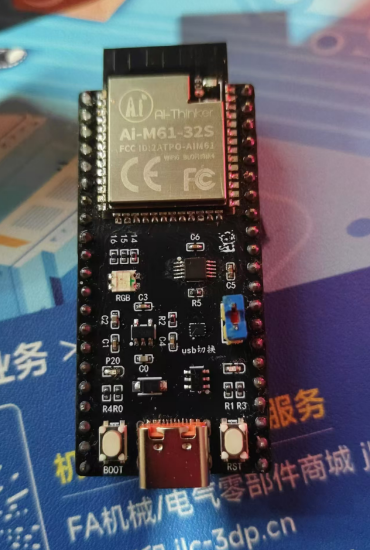

Let's turn on the LED:
input.mp4
PDF_AI_M61-32S Core Board.zip
Altium_AI_M61-32S core board.zip
PADS_AI_M61-32S core board.zip
BOM_AI_M61-32S Core Board.xlsx
93137
electronic


 京公网安备 11010802033920号

 MDE-25S361K


