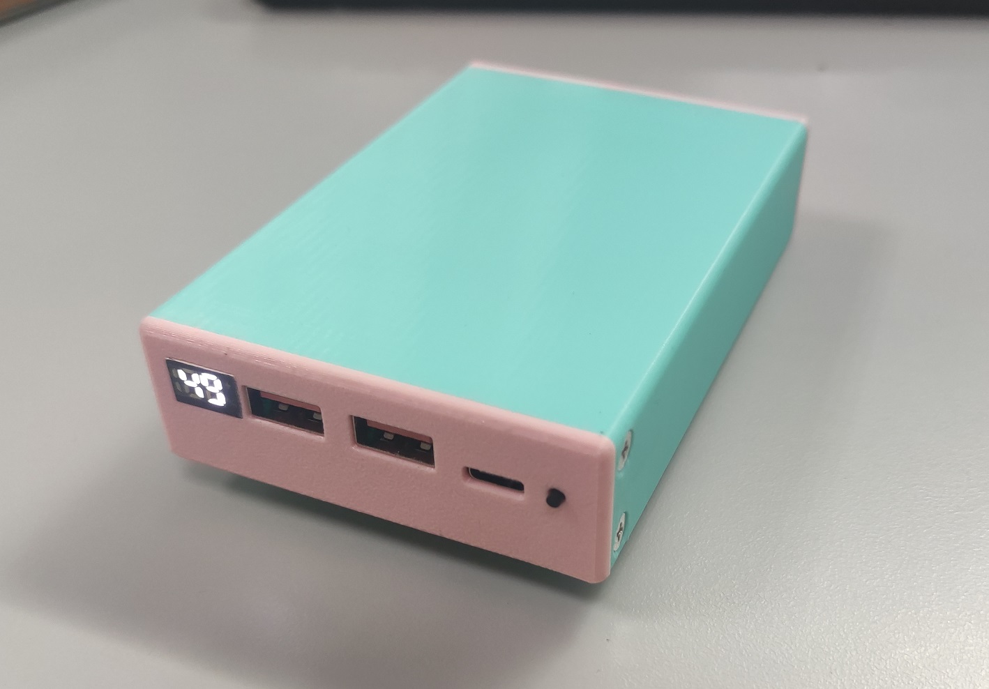
As the title suggests, this uses an IP5356 power bank IC and an XB8886 lithium battery protection IC. The peripheral design is very simple. The PCB is 72.5*19mm, which perfectly matches the size of the 21700.
The attached file is a 3D model of the 21700 casing, drawn according to the dimensions of the Lishen brand. It was printed perfectly using a printing press. If using an LG 21700, it will be slightly smaller than the Lishen and will require additional filler.
Purchase links for the USB-A female connector and 188 digital tube are provided:
USB 2.0 high-current AF 5P female connector 5A four-pin full-surface SMT 6.5/6.8mm short body 10.8 female connector (select 6.5*10.8). The
188 digital tube (percentage sign, % character, white digital display tube, small size fast charging lightning 12*8*4MM mini LED)
is also included. The
, and the 3D casing file are attached. The 10 holes circled in the image below require manual tapping of M3 threads, plus 10 M3*6 flathead screws for fixing.
The receiver and transmitter of a wireless remote controller based on the MQTT protocol.
Product Description:
This is a receiver and transmitter for a wireless remote control based on the MQTT protocol. It uses the Espressif ESP32-S3 module. Considering the receiver also uses an S3 module, a five-way switch was added with several I/O pins for use as a development board, for learning ESP-IDF, LVGL, etc. It is an
open-source project
under GPL 3.0 .
Project Functionality:
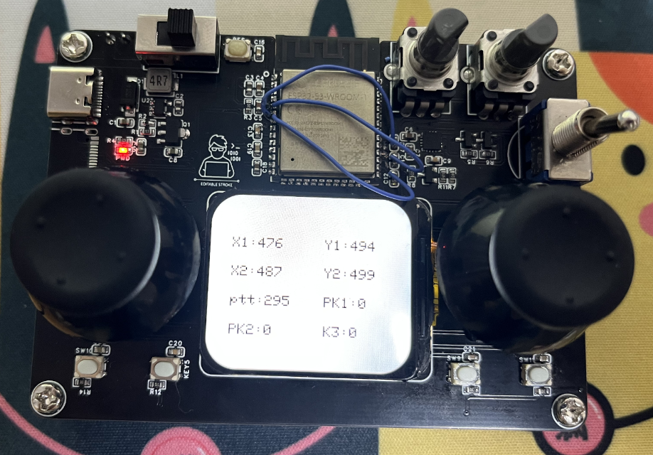
ADC acquires data from two joysticks and one potentiometer for transmission.
An LCD displays the acquired data.
Each joystick has a built-in button and a switch, totaling four independent buttons. This implements seven buttons.
The ESP32 connects to an MQTT server to send and receive remote control information. Hardware Design:
Power
Supply: A 3.7V lithium battery is used. First, an MT3540-F23 chip (mainly due to its small size) is used to boost the 3.7V lithium battery voltage to 5V, then an AMS1117 is used to reduce the voltage to 3.3V to power the entire system. A 100nF capacitor is added for filtering
the joysticks and potentiometer
(but the joysticks I bought are of poor quality, so a filtering algorithm needs to be added to the code).
The ESP32 minimum system
has an automatic download circuit, and the serial port chip used is the CH343P (still small in size). RST and BOOT buttons are brought out. An LCD
is displayed . The image shows the sending end. Due to the wrong I/O port being selected, a jumper wire was added, but this has been corrected!


RemoteControl_send.rar
RemoteControl_receive.rar
PDF_ESP32 Remote Control Transmitter and Receiver Based on MQTT Protocol.zip
Altium_ESP32 Remote Control Transmitter and Receiver Based on MQTT Protocol.zip
PADS_ESP32 Remote Control Transmitter and Receiver Based on MQTT Protocol.zip
BOM_ESP32 Remote Control Transmitter and Receiver Based on MQTT Protocol.xlsx
91350
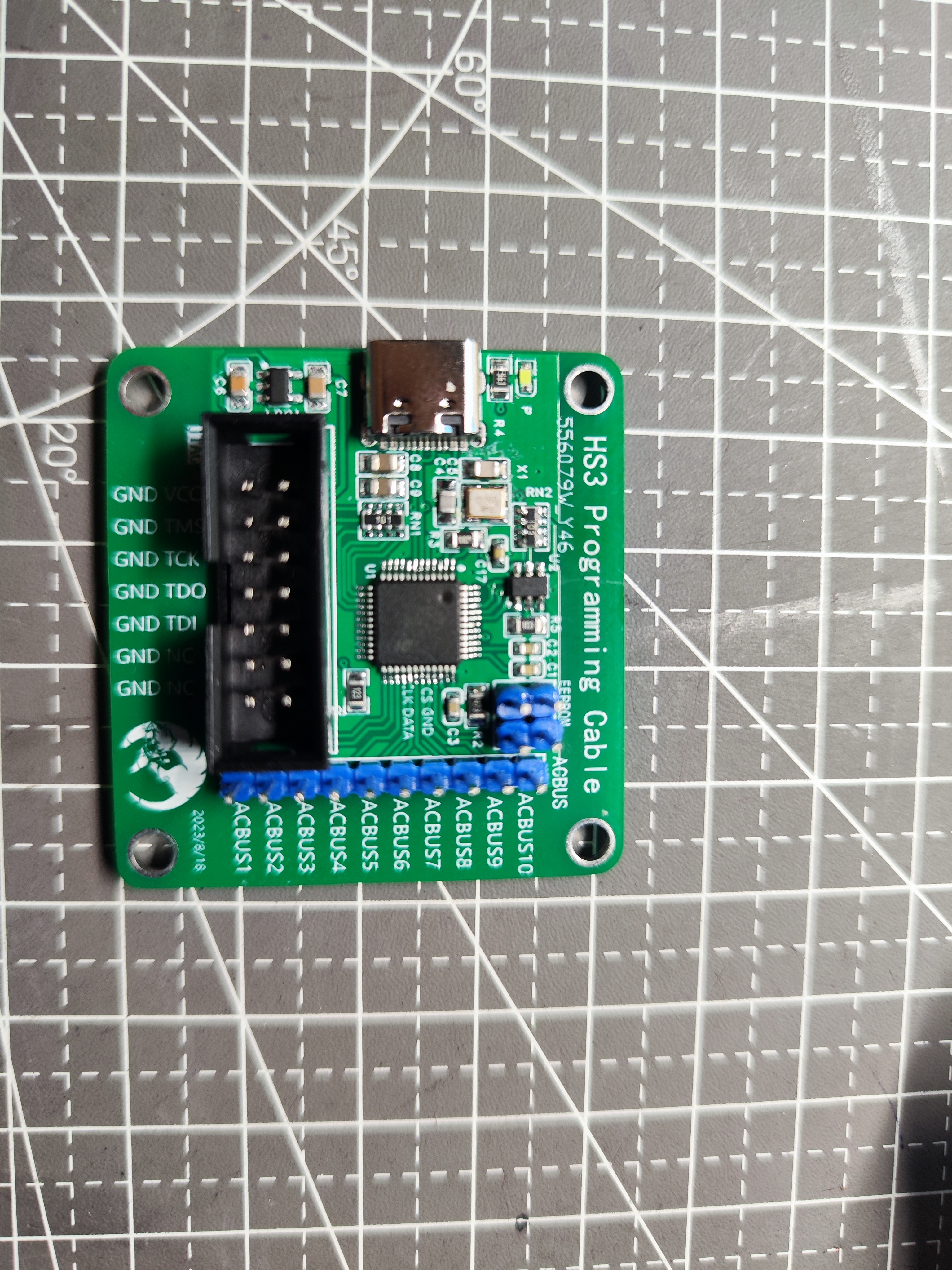
Xilinx JTAG HS3 FPGA Downloader
Great news! Great news!
Vivado 23.1 includes a downloader creation tool that can instantly turn any FT232 core board into a downloader. Mom no longer has to worry about me not being able to afford cable!
There are two main
types of Xilinx programmers: Xilinx's Platform Cable and Dejie's JTAG HS. Open-source programmers are mostly based on the JTAG HS3, which uses the FT232 microcontroller and has a maximum speed of 30Mbps.

Previously, creating an FT232 programmer required finding firmware and using additional tools to program the EEPROM. Bilibili's TeraiyTech improved the solution, allowing direct EEPROM programming via the FT232. Vivado version 23.1 added programmer creation functionality, allowing control of the FT232 EEPROM programming within a TCL, instantly turning the FT232 core board into a Xilinx programmer.

Official tutorial: UG908
https://docs.xilinx.com/r/2023.1-简体中文/ug908-vivado-programming-debugging/ Schematic reference design for programming FTDI devices supported by Vivado Hardware Manager
: https://china.xilinx.com/products/boards-and-kits/vck190.html#resources
Production steps
: 1. Connect the FT232H core board to the computer and ensure the device is working properly

. 2. Open the TCL terminal and execute the command `program_ftdi`.
Note: Vivado version must be 23.1 or higher.
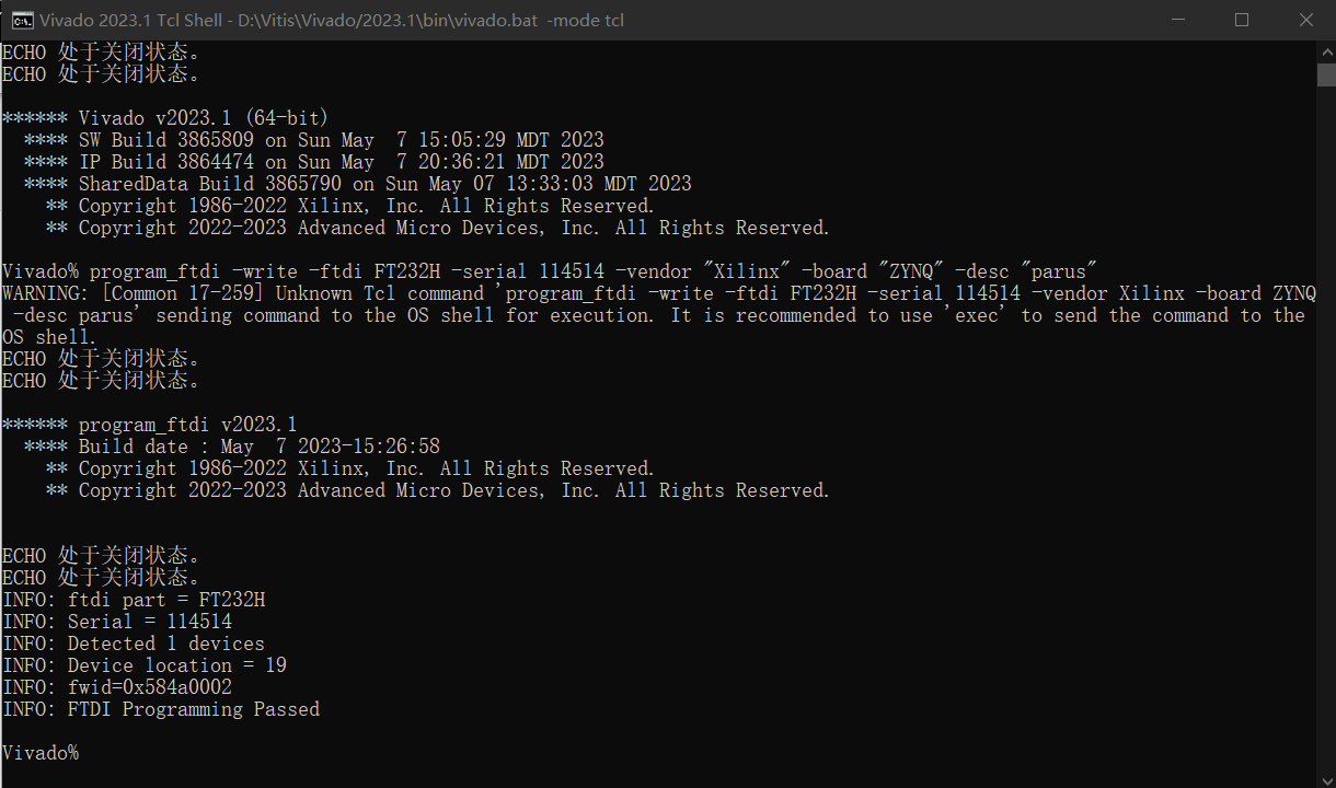
Command format
****** program_ftdi v2023.1
**** Build date : Apr 16 2023-14:45:22
** Copyright 1986-2022 Xilinx, Inc. All Rights Reserved.
** Copyright 2022-2023 Advanced Micro Devices, Inc. All Rights Reserved.
Short Description:
Write/Read to FTDI EEPROM for Xilinx JTAG Tools support
Syntax:
program_ftdi {-write -ftdi= -serial= [options] |
-write -filein= |
-read [-fileout=] |
-erase} [-help]
options:
Name Description
-f, -fdti Specify the ftdi device to be programmed
-s, -serial Serial number to be written into the EEPROM
[-v, --vendor] Vendor information
[-b, --board] Name of the board/product being programmed
[-d, -desc, -description] A short description of the board
-fi, -filein Input file with all fields to be written
[-fo, -fileout] File to which the FDI EEPROM should be read back
[-lh, -longhelp] Get long help description for program_ftdi util
Examples:
program_ftdi -write -ftdi FT2232H -serial 0ABC01 -vendor "my vendor co" -board "my board" -desc "my product desc"
program_ftdi -write -filein
program_ftdi -read
program_ftdi -read -fileout
program_ftdi -erase
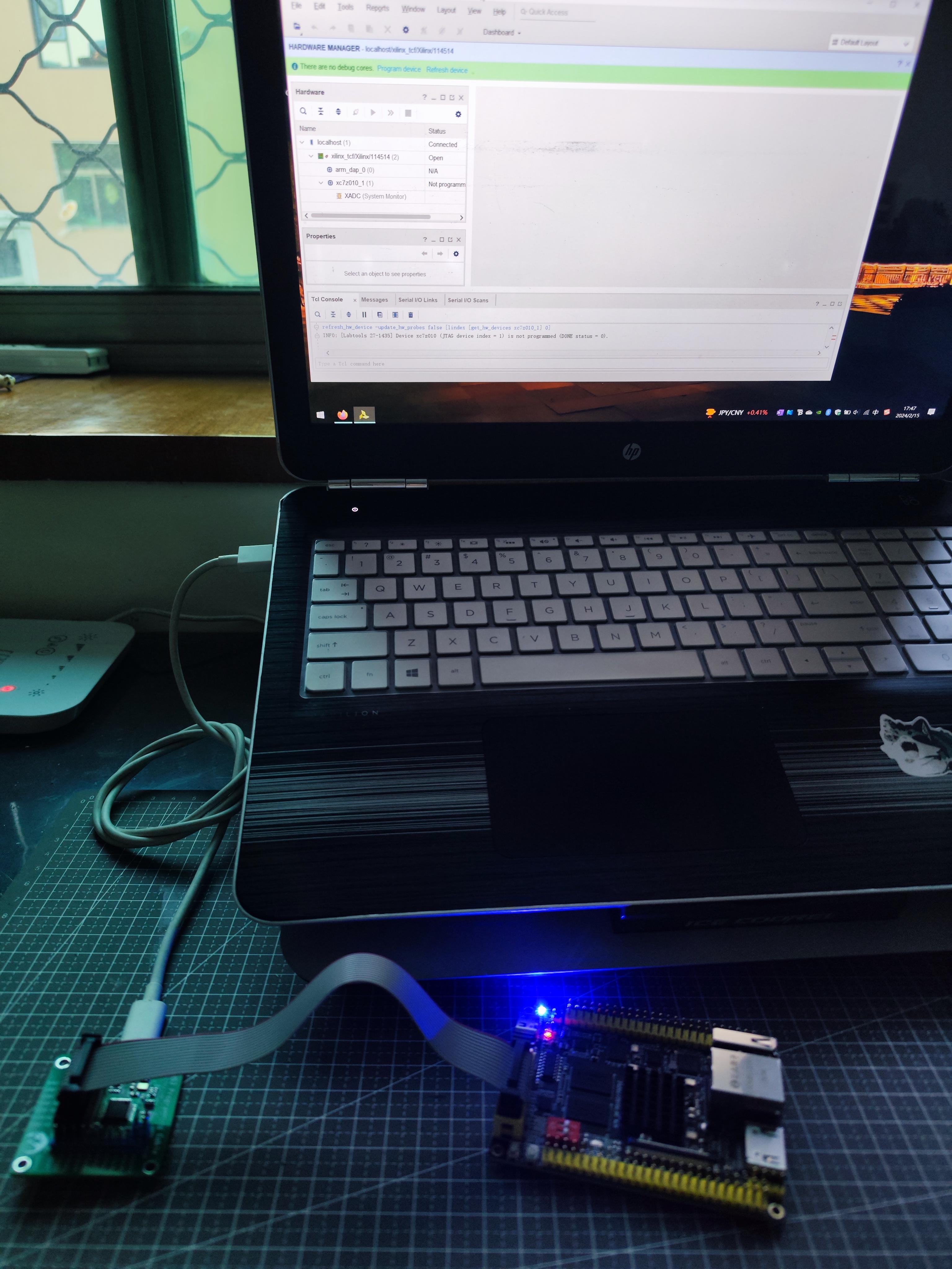
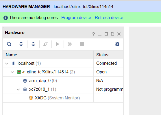
3. Connect the development board and perform a JTAG scan test. The development board is the ZYNQ
core board from Zhengdian Atom.

PDF_Xilinx JTAG HS3 FPGA Downloader.zip
Altium_Xilinx JTAG HS3 FPGA Downloader.zip
PADS_Xilinx JTAG HS3 FPGA Downloader.zip
BOM_Xilinx JTAG HS3 FPGA Downloader.xlsx
91351
electronic
 PCB front,
  back,
back, 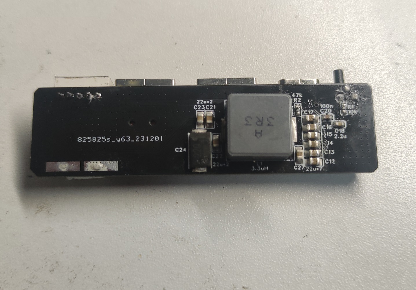 PCB + battery assembly diagram
 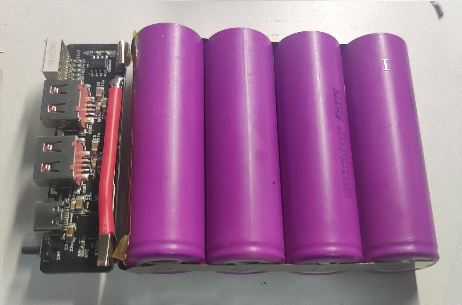 , and the 3D casing file are attached. The 10 holes circled in the image below require manual tapping of M3 threads, plus 10 M3*6 flathead screws for fixing.


 京公网安备 11010802033920号

 5082-4601-00300


