F1C200S Screen Development Board
Project Introduction:
The F1C200S Screen Development Board is an open-source hardware project based on the Allwinner F1C200S ARM926EJ-S core processor. The goal of this development board is to provide a low-cost, ultra-miniature platform suitable for Linux development, especially with support for screen interfaces.
Update Log
2023-12-25 Updated testing zImage, DTS, rootfs
2023-12-19 First release of
open-source software
UBoot:
https://gitee.com/fhcloud/f1-c200-s-uboot
(Please refer to the attachment for test programs)
Kernel:
https://gitee.com/fhcloud/f1-c200-s-kernel5_15_142
(Please refer to the firmware for test programs)
Buildroot:
https://gitee.com/fhcloud/buildroot-f1c200s
Test image download address: https://gitee.com/fhcloud/buildroot-f1c200s/releases/download/20231225/rootfs.tar
Hardware Version Notes:
Version V1 VDDA 3.0V LDO has an issue; the input and output are reversed. Please use version V2. Also, please carefully review the schematic diagram for the LDO section to avoid purchasing and using the incorrect 3.3V version. The development
board
features 16MB of onboard NOR flash memory and uses the F1C200S main control chip with 64MB of built-in DRAM. It also includes a USB Host interface, a USB Type-C port, and a CH340 serial-to-USB chip for development and debugging. A 2D preview of the development board is shown in

Figure 2.1 . The Allwinner F1C200S
main control chip
is a highly integrated, low-power mobile application processor suitable for multimedia audio and video devices. Based on the ARM 9 architecture, it integrates SiP DDR, simplifying its peripheral circuitry. The Allwinner F1C200S supports high-definition video decoding, including H.264, H.263, and MPEG 1/2/4 formats, and also features an audio codec and I2S/PCM interface. This processor is easy to use, cost-effective, and ideal as an entry-level Linux development board.
The schematic diagram for this part is shown in

Figure 2.2: F1C200S Main Control Schematic.
SVREF provides a reference voltage to the DRAM, requiring a voltage of VCC_DRAM/2. VCC_DRAM supplies power to the DRAM at 2.5V, VCC_IO supplies power to the GPIO at 3.3V, and VCC_CORE supplies power to the core at 1.2V. AVCC provides analog power; this is crucial, as failing to connect it will prevent the USB Host from enumerating devices. Note that this pin's power supply range is 2.5V-3.1V; using 3.3V will damage the internal circuitry. X1 is a 24MHz crystal oscillator providing the clock signal to the chip, using a 22pF load capacitor.
The SDMMC
interface is used to connect a Micro SD card. During system startup, U-Boot, the kernel, and RootFS can be loaded from the SD card to enable Linux boot.
The schematic diagram for this part is shown below:

Figure 2.3 SDMMC Interface Schematic Diagram
. The relevant circuit descriptions are as follows:
CLK: SDMMC clock, transmitting one command or data bit per clock cycle. The frequency can vary between 0 and 25MHz. The SD card bus manager can freely generate frequencies from 0 to 25MHz without any restrictions.
CMD: Command transmission line, commands are transmitted serially through this CMD line.
D0~D3: Data is transmitted through these data lines.
According to the SDMMC specification, the SDMMC line also requires a 10K pull-up resistor; its absence may affect data transmission. In this schematic, R7-R11 are the pull-up resistors. Additionally, to ensure power quality, a C22 filter capacitor is added.
The SHELL pin is the fixed pin for the SDMMC connector and is grounded here. The CD pin is used to detect whether the SD card is inserted; this part is left floating and unused.
CH340 Serial to USB:
This circuit is used for user connection to system debugging interrupts. Its function is to convert the TTL serial port to a USB interface, allowing users to connect to the serial port on their computer for debugging.
It's important to note that because the F1C200S's UART0 interface (PE0/PE1 pins) is occupied by the touchscreen's I2C interface, this development board connects the CH340's serial port to the F1C200S's UART1 (PA2/PA3 pins). We will need to modify the code accordingly when compiling U-Boot and the kernel.
The schematic diagram for this part is shown below:


Figure 2.4 CH340 Serial-to-USB Schematic Diagram
. As shown above, this part, in addition to serial-to-USB conversion, also provides system power. Connecting the debug port via a Type-C cable will simultaneously power the development board. The 5.1K resistor on the board is used for double-ended Type-C cables to identify the slave device and provide it with power. If R12 and R13 are not soldered, the board will not be powered when using a double-ended Type-C cable. D2 is a TVS transient voltage suppressor diode used to protect components on the PCB board from electrostatic discharge. The
three-channel DC-DC interface
mainly provides power to the main control chip, using the SY8089A1AAC, with a maximum output current of 2A per channel.
The schematic diagram of this part is shown below:

Figure 2.5 Schematic diagram of the three-channel DC-DC interface
. In the figure, C24/C25/C27/C28/C30/C31 are DC-DC input/output filter capacitors, L2/L3/L4 are the corresponding inductors, and R16/R17/R18/R19/R20/R21 are DC-DC feedback resistors used to adjust the chip output voltage. The EN pin is the chip enable pin, which is active high. Since the F1C200S does not have requirements for power-on timing, this development board is directly connected to the power input. After power-on, the chip will start running and output voltage directly.
In this module, we used a 2520 inductor, which is smaller in size than a regular inductor. However, the 2520 inductor has a slightly higher DCR (DC resistance) parameter than a regular inductor. The formula for calculating the inductance value can be found below:

Figure 2.6 DCDC Current Inductance Value Calculation Formula
Where:
L is the calculated inductance capacity,
Vout is the output voltage of the buck converter chip,
Vin is the input voltage of the buck converter chip
, Fsw is the switching frequency of the chip, SY8089 is 1.5MHz, which is 1500000Hz, and
Iout,max is the maximum output current.
As shown in the figure below, the inductance value of this development board is directly referenced from the SY8089 datasheet, and a compromise value of 1.5Uh is chosen:
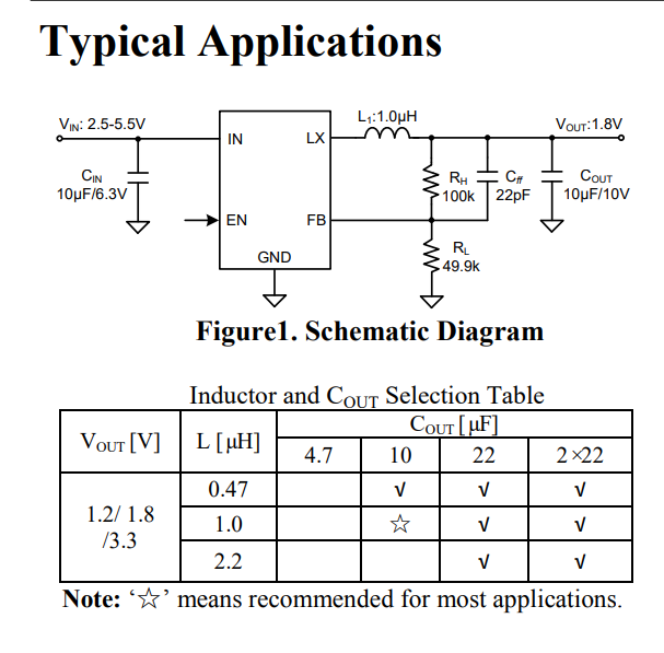
Figure 2.7 Typical Applications of SY8089 and Capacitor and Inductor Selection Table.
The feedback resistor of the chip controls the output voltage of the chip, which can be calculated with reference to the formula below:

Figure 2.8 SY8089 Chip Feedback Resistor Calculation Formula.
Where:
Rh is the resistance value of the upper voltage divider resistor ,
Rl is the resistance value of the lower voltage divider resistor
, and 0.6V refers to the chip's Vfb, which is the feedback resistor
Vout, i.e., the final voltage output value
. Here, we need to determine Rl and Vout, and then substitute them into the formula to calculate Rh.
To minimize power consumption under light loads, it is best to choose larger resistance values for RH and RL. It is strongly recommended that RL use a value between 10k and 200k.
AVCC 3V LDO
This part is used for AVCC 3V power supply, using an XC6206 3V LDO, reference number U10. Since it is relatively simple, it will not be described in detail here.
The SPI Nor
Flash provides a second boot method for the F1C200S chip.
Upon power-up, the F1C200S first boots from its internal BROM (built into the chip and cannot be erased).
It first checks if a card is inserted into SD0; if so, it reads 8KB offset data from the card to verify its validity. If it's BROM boot, the process ends; otherwise, it proceeds to the next step.
The second step checks if the SPI0 NOR FLASH exists and contains valid boot data. If it's BROM boot, the process ends; otherwise, it proceeds to the next step.
The third step checks if the SPI0 NAND FLASH exists and contains valid boot data. If it's BROM boot, the process ends; otherwise, it proceeds to the next step.
Finally, since no bootable medium is found, the system enters USB FEL mode, allowing for USB programming.
The SPI Nor Flash is compatible with NAND Flash, but most bare-metal documentation is based on SPI Nor Flash, so a W25Q128JVEIQ 128Mbit (16Mbyte) SPI Nor Flash is soldered here.
The schematic diagram for this part is shown below:

Figure 2.9 W25Q128JVEIQ Schematic Diagram.
Where:
R4 is a pull-up resistor (the F1C200S also has an internal pull-up resistor, so it doesn't need to be soldered), preventing the chip from incorrectly writing data when there is no power supply;
C16 is a filter capacitor;
SW2 is the FEL mode switch. After shorting SPI_MISO to ground, the F1C200S will not be able to detect the SPI Nor Flash, thus entering USB FEL mode. At this time, you can release the button to program the content to the SPI Nor Flash.
/WP is the SPI Nor Flash protection pin, active low. When active, data cannot be written.
/HOLDor/RESET are the SPI Nor Flash hold or reset input pins.
Due to the default settings inside the SPI Nor Flash, the chip will still operate even if the /HOLDor/RESET and /WP pins are not pulled high.
2.7 External I/O Interface
This section exposes unused I/O pins for connecting other devices. C35 is a filter capacitor used to ensure power quality. The pin functions for this section can be found in the following diagram (source: chip datasheet, pages 14/15):

Figure 2.10 External I/O Interface Pin Functions
USB OTG/USB TYPE-C
This section connects to the chip's DP/DM pins, serving as the chip's USB interface.
USB Type-C is used for USB Fel mode programming and has no power input/output capability.
The USB OTG pin can be used to connect other USB devices, providing a 5V output. It can also be connected to a dual-ended USB Type-A cable for USB Fel mode.
The schematic diagram of this module is shown below:


Figure 2.11 USB OTG/USB Type-C Schematic Diagram
Note that the development board does not have an ID line (used to identify the USB mode). Therefore, when writing the device tree, we need to explicitly specify the USB mode as host or slave.
The backlight driver
section is used to drive the RGB screen backlight. Standard 40-pin RGB screens generally use series backlighting. Since the development board's power supply is only 5V, we need to use a backlight driver chip to boost the voltage to a suitable level to drive the screen backlight. Simultaneously, the backlight driver chip uses constant current control to prevent excessive current from burning out the backlight LEDs. The schematic diagram for this section is shown below:

Figure 2.12 Backlight Driver Schematic Diagram.
Where:
C19 and C20 are filter capacitors. The voltage rating of capacitor C19 needs special consideration. The backlight voltage of a typical RGB screen is generally above 18V (white LED voltage drop 3V*6 series). Insufficient capacitor voltage will cause damage.
BL_CTR is the chip's backlight control pin, which is directly connected to a pull-up resistor. In future development, the BL_CTR pin can be connected to the PWM pin of the F1C200S, allowing for flexible control of screen brightness. Furthermore, with constant current driving, there is no noticeable flicker when controlling brightness.
L1 is the inductor for the boost circuit. Generally, 10uH or 22uH is sufficient; detailed calculations using formulas are not required. However, it's crucial that the current does not exceed the inductor's rated current.
R5 is the chip's feedback resistor, used to regulate the output current. The calculation formula can be found in

Figure 2.13: Feedback Resistor Calculation Formula.
Here, we choose 20mA, so R1 = 0.25/0.020 (Ω) = 12.5Ω, choosing 12Ω as the closest value.
The chosen 20mA current can be referenced in the screen datasheet:

Figure 2.14: Screen Datasheet Circuit Diagram.
As shown above, the LEDs are configured as 2 parallel and 5 series, with a rated current of 40mA. For safety, we chose 20mA, which will result in some brightness loss.
The 40-pin RGB/touch interface
can be found in the screen datasheet. Since the F1C200S only supports RGB565 and RGB666, RGB666 is used here, disabling the lower two bits of the RGB colors. This minimizes the impact on the final color. Additionally, the F1C200S has built-in color dithering, which more closely approximates the RGB888 effect.
It's important to note that CTP_SDA/CTP_SCL should ideally have pull-up resistors. Internal pull-ups are used here, so no resistors are added. The schematic for this part is shown below:

Figure 2.15 RGB/Touch Interface Schematic.
Pin definitions can be found in the screen datasheet, as shown below:

Figure 2.16 Pin Definitions from the Screen Datasheet.
Development Environment Setup:
WSL installation
(to be supplemented);
VMware virtual machine installation
(to be supplemented );
VSCode configuration (optional).
Using the DeviceTree plugin for VSCode, we can achieve code highlighting for device tree files. We can also use VSCode when editing C language code, so configuring VSCode is essential.
Since VSCode installation is relatively simple, this manual only provides the download address; users can install it themselves before reading further.
VSCode download address: https://code.visualstudio.com/
After installing VSCode, we will start installing the DeviceTree plugin. Search for the DeviceTree plugin in the store and click install:

Figure 3.x. The installation of the DeviceTree plugin
is similar. It is recommended that readers also install the Chinese language pack. Search for CN and refer to the following figure for installation. After installation, restart VSCode as required.

Figure 3.x. Installing the Chinese language pack .
SD Card Partitioning:
Open the installed Ubuntu 18.04 virtual machine, insert the SD card to be partitioned into the computer's USB port, right-click the USB storage icon in the lower right corner of VMware, click Connect, and connect the SD card to the virtual machine. The specific operation process is shown in the following figure:

Figure 3.x Connecting the device to the virtual machine
Click the icon in the lower left corner of the desktop, enter All Applications, and then search for GPartd, as shown in the following figure:

Figure 3.x GPartd tool
At this time, you need to enter a password. Enter the user password to escalate to the root user, as shown in the following figure:

Figure 3.x Password prompt
Next, select the SD card we need to format in the upper right corner. The default is /dev/sda, which is our virtual machine's system disk. We need to switch to the SD card. Be careful here, sdb may not be our SD card. After completing the switch, right-click in the position shown in the figure, click "Uninstall", then click the "Delete" button to delete the original partition in the SD card, and finally click OK to confirm the deletion. The specific process can be referred to in the following figure:


Figure 3.x GPartd formatting SD card process
Next, start creating partitions. First, create a boot partition, which is used by u-boot to read device tree, kernel and other files. We need to leave some space in front of the partition for u-boot and SPL program storage, as shown in the following figure. First, click the button in the upper left corner to create a new partition, and then create the boot partition as shown in the following figure.


Figure 3.x shows the process of creating the BOOT partition.
Here, 1 Mib of space is reserved for U-Boot and SPL, which is more than enough to store these programs.
Next, the rootfs partition is created. We will use all the remaining space as rootfs, and select ext4 as the file system, as shown in the following figure:

Figure 3.x shows the rootfs partition creation process
. Finally, click save, confirm, and the changes will take effect. Remove the SD card for later use. The operation can be referred to the following figure:

Figure 3.x shows saving partition information .
U-Boot Compilation
Introduction to U-Boot and F1C200S Boot Process
U-Boot, short for Universal Boot Loader, is an open-source boot loader widely used in the boot process of embedded devices. As a powerful and widely used boot tool, it supports multiple processor architectures and embedded platforms.
During the system startup phase, U-Boot is responsible for initializing various hardware components, including but not limited to core hardware units such as the CPU, memory controller, interrupt controller, and timers. In addition, it is also responsible for loading the operating system kernel and root file system. To facilitate user configuration, debugging, and maintenance, U-Boot provides an interactive command-line interface.
Typically, U-Boot is used as the first-stage bootloader, its primary responsibility being to load and execute the operating system from various storage media (such as flash memory, SD card, or network). This characteristic makes U-Boot a crucial player in the embedded device boot process.
U-Boot's features and functions are as follows:
Cross-platform compatibility: U-Boot supports a wide range of processor architectures, including but not limited to ARM, x86, PowerPC, and MIPS, and can run on various embedded platforms. It can flexibly adapt to different hardware configurations and system requirements.
High customizability: U-Boot provides rich configuration options and extensibility, allowing developers to customize and optimize it according to specific embedded system needs.
Multiple boot methods: U-Boot supports multiple boot modes, including serial port boot, network boot (via TFTP or NFS), SD card boot, and flash memory boot.
Interactive command-line interface: U-Boot provides an interactive command-line interface through which users can perform various tasks such as device initialization, memory testing, file system operations, and network configuration.
File system diversity: U-Boot supports multiple file system types, such as FAT, EXT2/3/4, UBIFS, etc., and can load and boot different types of root file systems.
Powerful debugging and troubleshooting tools: U-Boot provides a series of functions for system debugging and troubleshooting, such as memory testing, device registration information display, and logging, providing convenience for developers.
In the development of the F1C200S chip, the first thing we need to adapt is U-Boot. Let's take a look at the F1C200S boot process:
When the power is turned on, the F1C100S's internal BROM (a non-erasable built-in chip) begins booting.
First, it checks if an SD card is inserted in SD card slot 0. If so, it reads 8K offset data to determine if it is valid boot data. If the data is valid, the BROM boot ends; otherwise, it continues to the next step.
It checks if the SPI0 NOR FLASH (such as W25QXXX or MX25LXXX) exists and verifies if it contains valid boot data. If valid data exists, the BROM boot ends; otherwise, it continues to the next step.
Next, the system checks if the SPI0 NAND FLASH exists and verifies if it contains valid boot data. If valid data is found, the BROM boot process ends; otherwise, proceed to the next step.
Since no bootable media was found in the previous steps, the system switches to USB FEL mode, where USB can be used for programming.
After the BROM boot process is complete, the SPL program (Second Program Loader) is loaded, responsible for loading U-Boot into RAM. Only then is U-Boot truly loaded.
Once U-Boot starts, it loads the device tree configured by the user during compilation, loads the corresponding drivers, locates the user-stored kernel program or configuration file, and then starts the kernel according to the user-configured boot command and Linux kernel parameters. After the kernel starts, U-Boot's mission is complete. It's important to note that U-Boot also needs to configure the device tree, but this device tree mainly helps U-Boot load memory and other basic peripherals, so the configuration doesn't need to be particularly complex; generally, only the memory and serial port nodes need to be configured.
U-Boot source code clone:
The U-Boot source code is hosted on GitHub, and we can retrieve it directly using the `git` command.
U-Boot source code address: https://github.com/u-boot/u-boot/tree/master
Author's adapted U-Boot source code address: https://gitee.com/fhcloud/f1-c200-s-uboot
The author's adapted U-Boot currently uses the master branch. Since the master branch code may be updated later, this guide will use the most recent U-Boot version (v2023.10) to guide users in modifying and configuring it to compile their own U-Boot.
First, open the WSL environment we installed, as shown in

Figure 4.x. Start WSL
and enter the following command to begin cloning the project:
`git clone https://github.com/u-boot/u-boot.git -b v2023.10 --depth=1`.

(Figure 4.x shows the U-Boot cloning process.
) Where:
`-b v2023.10` specifies the tags as v2023.10; `--depth=1` sets
the download depth to 1, which can skip previous git commits and speed up the download process.
Type `cd u-boot` to enter the source code directory. Here we are prompted that we are currently in header-separated mode. Simply create a new branch as required and start developing under the new branch:
`he@DESKTOP-EP0P00N:~$ cd u-boot
u-boot/ u-boot-master/`
`he@DESKTOP-EP0P00N:~$ cd u-boot`
`he@DESKTOP-EP0P00N:~/u-boot$ git checkout -b dev` `
Switched to a new branch 'dev'`
If you are not using Git to manage your code, you don't need to do the above steps; just ignore the prompt.
Configuring the U-Boot Cross-Compilation Environment:
In the previous chapter, we configured the cross-compiler arm-linux-gnueabi. We only need to modify the U-Boot Makefile and add the following content to configure the cross-compilation environment:
`ARCH ?= arm
CROSS_COMPILE ?= arm-linux-gnueabi-
` `ARCH CROSS_COMPILE` specifies the architecture and compiler used in the compilation. The `?=` indicates that if the variable has already been specified, the variable provided here will not be used. See the screenshot below for the modified file:

Figure 4.x U-Boot Compiler Settings
 Figure 2.1 . The Allwinner F1C200S
  Figure 2.2: F1C200S Main Control Schematic.
  Figure 2.3 SDMMC Interface Schematic Diagram
 Figure 2.4 CH340 Serial-to-USB Schematic Diagram
  Figure 2.5 Schematic diagram of the three-channel DC-DC interface
  Figure 2.6 DCDC Current Inductance Value Calculation Formula
  Figure 2.7 Typical Applications of SY8089 and Capacitor and Inductor Selection Table.
  Figure 2.8 SY8089 Chip Feedback Resistor Calculation Formula.
  Figure 2.9 W25Q128JVEIQ Schematic Diagram.
  Figure 2.10 External I/O Interface Pin Functions
 Figure 2.11 USB OTG/USB Type-C Schematic Diagram
  Figure 2.12 Backlight Driver Schematic Diagram.
  Figure 2.13: Feedback Resistor Calculation Formula.
  Figure 2.14: Screen Datasheet Circuit Diagram.
  Figure 2.15 RGB/Touch Interface Schematic.
  Figure 2.16 Pin Definitions from the Screen Datasheet.
 Figure 3.x. Installing the Chinese language pack .
  Figure 3.x Connecting the device to the virtual machine
  Figure 3.x GPartd tool
  Figure 3.x Password prompt

 Figure 3.x GPartd formatting SD card process
 Figure 3.x shows the process of creating the BOOT partition.
  Figure 3.x shows the rootfs partition creation process
  Figure 3.x shows saving partition information .
  Figure 4.x. Start WSL
  (Figure 4.x shows the U-Boot cloning process.


 京公网安备 11010802033920号

 MAX6358MTUK-T


