This is an optimized version of the O and Q mini heating stages 0402, supporting switching of decoy voltages. Please refer to the original project for assembly and other related information.
The schematic and PCB have been reorganized (for a better look), and the layout of some components has been optimized.
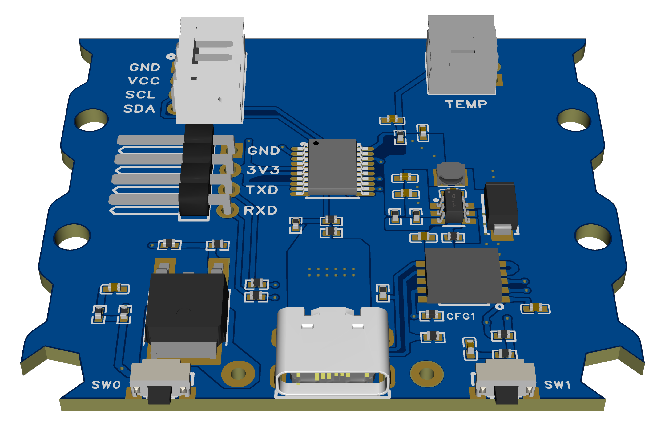
The CH224K's CFG1 configuration pin has been brought out, allowing for configuration of the induced voltage via a resistor (no soldering required, see next item).
All CFG1/CFG2/CFG3 pins of the CH224K are connected to the microcontroller's I/O ports, allowing program-controlled induced voltage.
The 5.1K pull-down resistor pads for CC1 and CC2 have also been retained (the 224K has this resistor built-in and generally does not require soldering).
C6 has been changed from 10uF/25V to 4.7uF/25V, making the 0402 package easier to find (confirmed in the datasheet, does not affect usage).
The screen and temperature sensor use a standard PH2.0 interface for easier socket soldering (wires can also be soldered directly).
The position of the four-pin serial port flashing interface on the board has been adjusted to a 2.54mm header interface for easier wiring.
USB flashing support has been added (software simulation, requires STC-ISP software to install the driver).
Component attributes have been fixed, and all components have been changed to those from LCSC Mall, allowing direct use of the generated BOM.
(Press SW1 ) The button power-on function will switch between 5V/9V/12V/15V/20V to induce voltage (release immediately after power-on, no need to hold down the button). No interface was provided because it's too cumbersome.
Regarding the soldering order (also applicable to the original):
Do not solder the microcontroller and CH224K first. The purpose is to ensure the DC step-down section is working properly. After plugging in the USB port, use a multimeter to measure the voltage between 3V3 and GND to see if it is around 3.3V. Once confirmed, then solder the CH224K and microcontroller.
Otherwise, if the inducer voltage is too high, the step-down output voltage may burn out the CH224K and microcontroller (although theoretically an overvoltage protection circuit could be added to 3.3V, it's not really necessary).
USB flashing method:
Press and hold SW0 to enter USB flashing mode. Then refer to the STC forum posts for software to simulate USB for direct download. STC8/STC32 microcontrollers without hardware USB can also download and install drivers and flash via USB.
(The success rate of USB flashing is not very high in actual testing, the reason is unknown. If you do not want to use it, you can skip soldering the two 22Ω resistors R32 and R33.)
After flashing the firmware for the first time, press and hold the SW1 button to switch the decoy voltage and check if the voltage displayed on the screen changes compared to the last power-on (try several times to see if different voltage levels can be decoyed).
(The modified source code and compiled firmware are provided in the attachment.)


 京公网安备 11010802033920号

 HLMP-CW36-Z1000


