Project Introduction
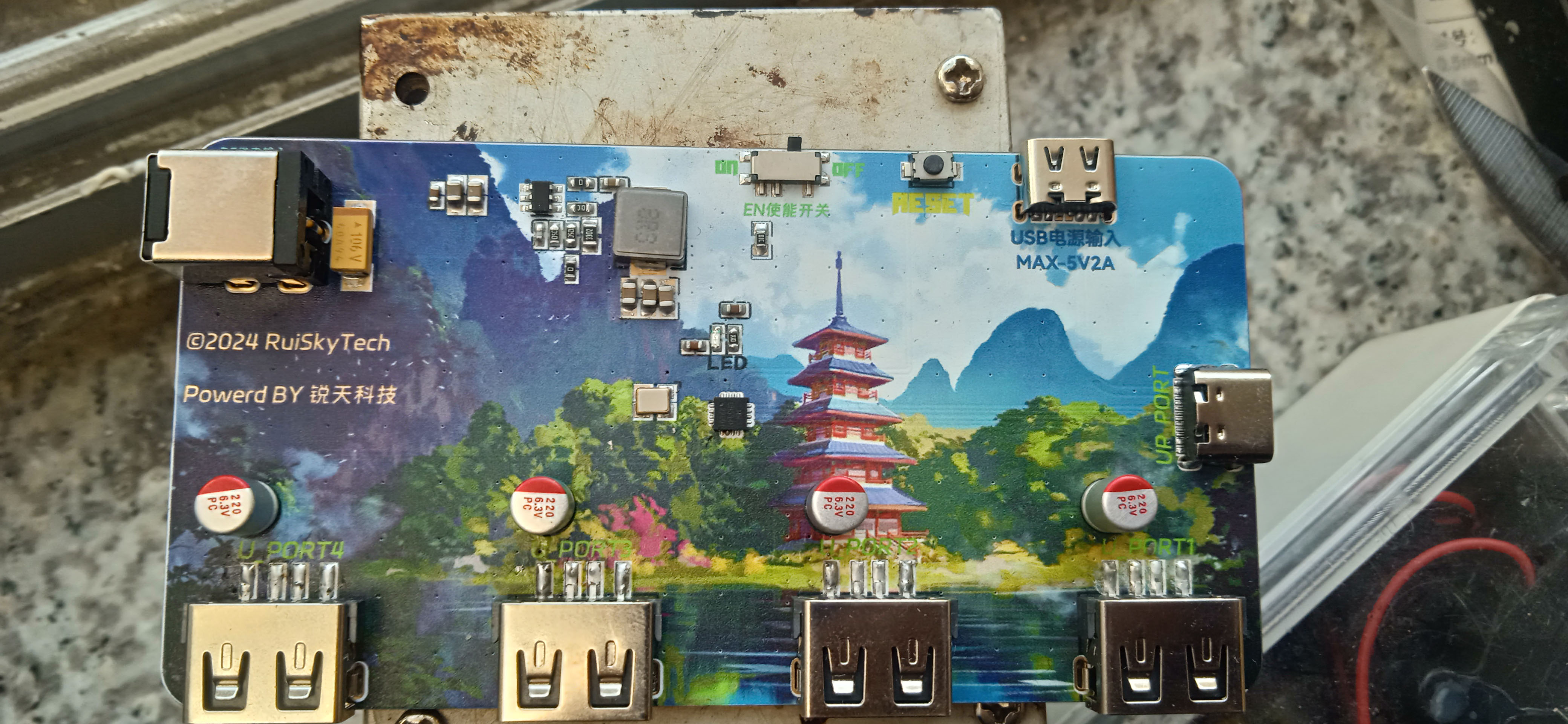
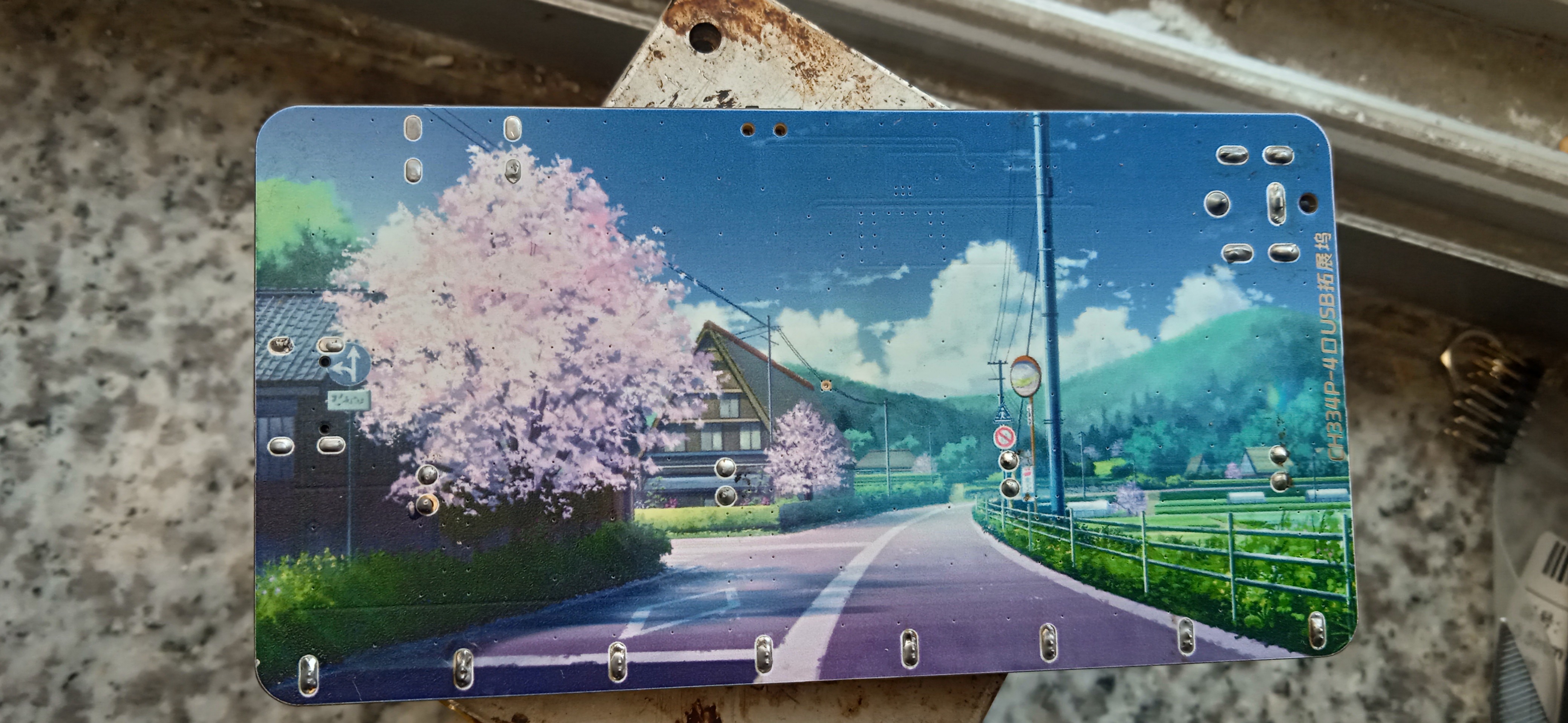
: This is a color silkscreened expansion dock
project. Features:
4-port USB hub, providing four USB 2.0 downstream ports, backward compatible with USB 1.1 protocol specifications,
supporting high-performance MTT mode, providing an independent TT for each port to achieve full-bandwidth concurrent transmission, with a total bandwidth four times that of STT.
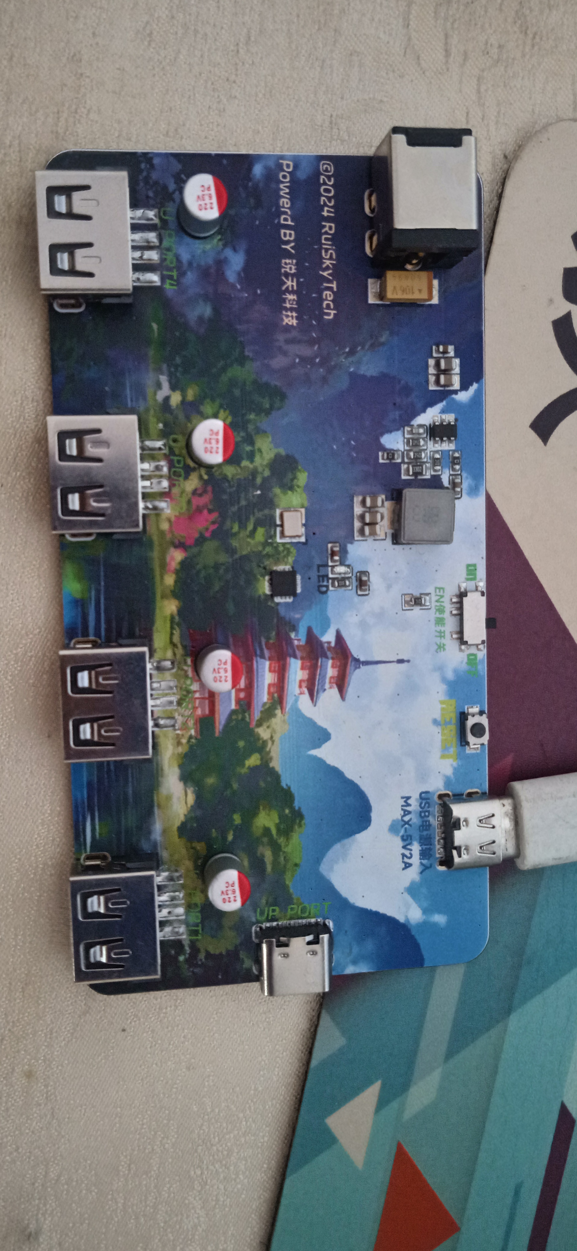
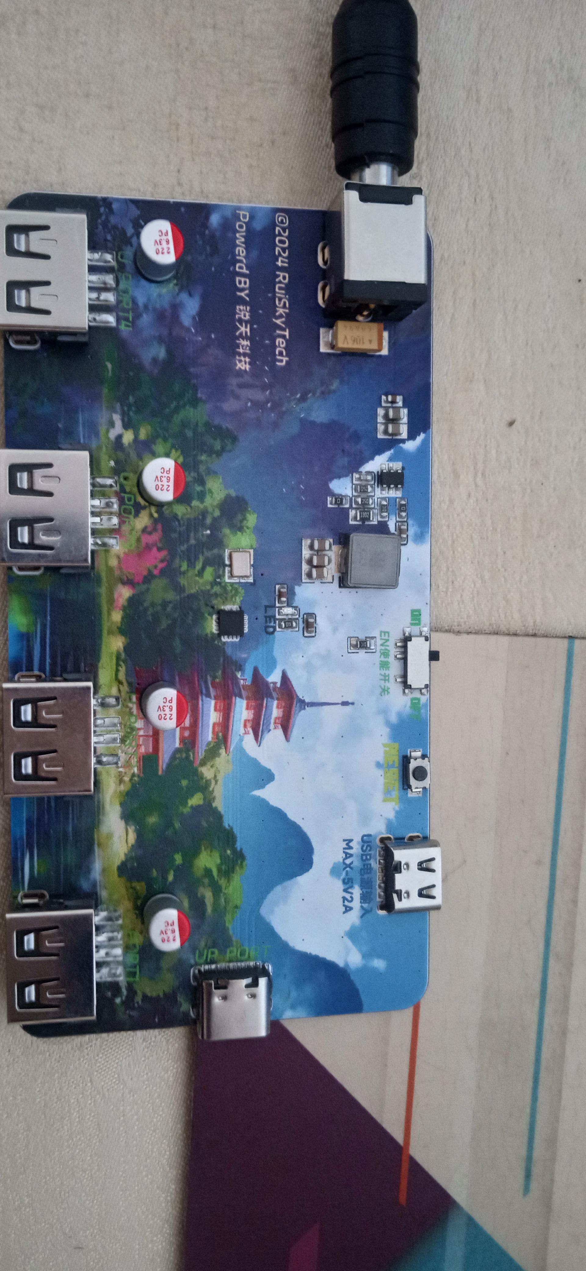
DC input port, eliminating worries about insufficient power supply from the computer's built-in USB ports.
Maximum 3A output current, even for charging (when using the DC interface).
Project Parameters:
USB HUB controller chip uses CH334
synchronous buck converter; TPS563201, 3A output current, compact and powerful,
providing one DC007 and one Type-C power port, one USB-C upstream port, and four USB-A downstream ports.
[Image of the actual product]

CH334DS1.PDF
tps563201.pdf
2024-10-19 16-12-43.mp4
PDF_[Color Silkscreen] USB-HUB Based on CH334P.zip
Altium_[Color Silkscreen] USB-HUB Based on CH334P.zip
PADS_[Color Silkscreen] USB-HUB Based on CH334P.zip
BOM_[Color Silkscreen] USB-HUB Based on CH334P.xlsx
91559
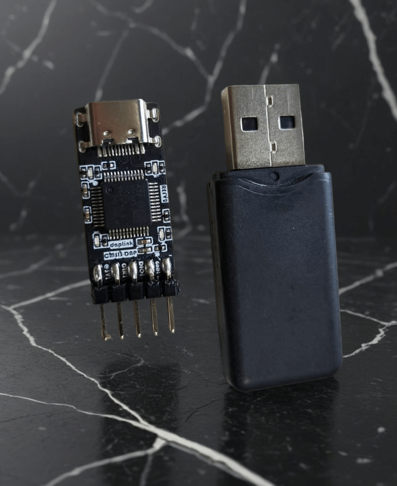
The smallest Daplink ever - with 485 communication
This project is an extension of the open-source mini daplink V2 project by Xifan Fangjiang. The Kicad project has been ported and adapted to JLC, and the TTL serial communication has been changed to the 485 communication mode. Thanks to Xifan Fangjiang for his selfless open-source spirit.
Project Overview:
This project is a modified version of Daplink V2 by the developer "Xifan Fangjiang". While retaining the original mini size design, it adds a 485 communication circuit, facilitating debugging and testing in fields such as industrial automation and manufacturing. Its size is only about the size of a USB-A cable (roughly the size of the top of a data cable). If you do not require 485 communication, you can try to understand, learn, and replicate Xifan Fangjiang's original project, which is attached.
ARM official DAPLink project address: https://github.com/ARMmbed/DAPLink
Heze official DAPLink project address: https://gitee.com/hanszeng/daplink
Project features:
Supports SW mode debugging and downloading, supports 485 communication; --241019
Theoretically, this design is compatible with four types of downloaders. ST-Link and DAPLink have been tested; only the relevant firmware needs to be flashed. --241019
Notes:
The main controller can use multiple series of F103 models. Different models require different firmware flashing. If you are capable of compiling the project yourself, you can use the official ARM project for modification. --241019
The ST-Link firmware does not have onboard LED drivers, so the LEDs will not light up when using ST-Link. An upgrade is required after flashing the ST-Link firmware; the specific method will be mentioned later. --241019 The
ST-Link firmware has a virtual USB drive, but no virtual serial port. This means you can use it as a downloader and download via virtual USB drive, but it cannot be used as a serial port. This issue is currently unresolved; perhaps a more advanced firmware is needed? —241019
J-Link theoretically supports this, so I suggest everyone give it a try. Feel free to add your suggestions in the comments section and contribute to the open-source community. —241019
The pinout in this version is rather messy, as required by my project. If you find it unsuitable or inconvenient, please feel free to modify it further, but remember to open-source it so everyone can learn from it. —241019
Different downloader firmwares have inconsistent support for chips with different kernels. Pay attention to the firmware's applicability and flash it according to your own needs.
Possible problems and solutions:
For some flashing steps and firmware upgrade issues, please refer to this article: https://blog.csdn.net/weixin_42880082/article/details/127293349
St.'s official ST-Link upgrade guide: https://www.st.com/resource/zh/release_note/DM00107009-.pdf
Article on operating the virtual serial port supported by STLink 2.1: https://blog.csdn.net/weixin_42880082/article/details/127963348
For space-saving purposes, the USB interface should be a recessed design. Using other interfaces may lead to incompatibility issues and unstable soldering. However, it's worth trying; you might discover a new idea.

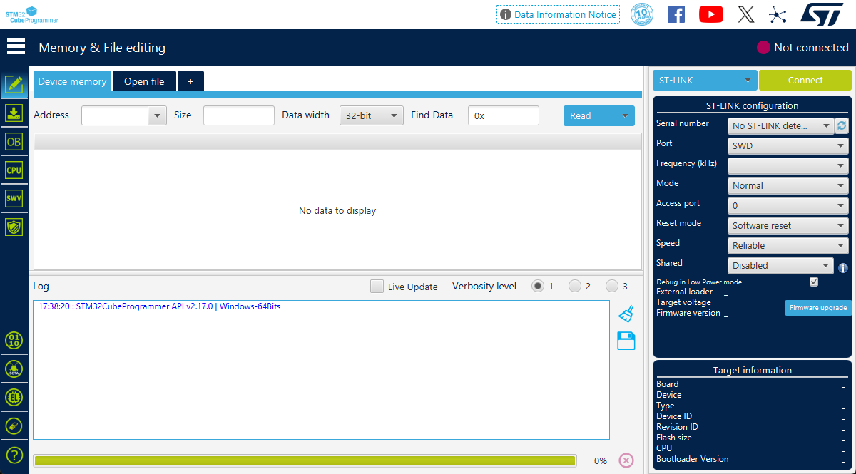
How to use the SW interface to flash firmware into the programmer?
QA: JLink users can use JFlash, STLink users can use STMCUBOPROGRAMER, and DAPLink users can use OpenOCD or PYOCD command lines. Specific operations are not detailed here; please search online.

Sign --DF241019 ----- Recorded on 20241019
Programmer Usage:
The pins on the chip side of the front are used for flashing other chips. A is the A signal in the 485 communication signal pair. Note that the 5V power supply is not isolated; it can power the target via USB, or it can introduce electrical shocks from the target into the USB. This means that introducing high voltage from the pins will damage the USB device! !! Please be extremely careful not to connect the wires incorrectly!!!
It is recommended to use only the dio, clk, and gnd wires for debugging. During debugging, the target board needs to be powered by other components.

The pins on the reverse side of the programmer are for programming the firmware and for the B signal of the 485 communication. Pay attention to the arrow direction and do not connect the wires incorrectly.

For feedback and answers to questions
, please leave a message in the comments section if you encounter any hardware difficulties or questions. The author will try to reply as soon as possible.
STLinkV2.J28.M18.bin
air32_daplink_v2.hex
air32_daplink_v1.hex
air32_daplink_v1_iap.hex
air32_daplink_v2_iap.hex
ARM official DAPLink.zip
Original project DAPLink-V2.zip
PDF_The smallest Daplink in history - with 485 communication.zip
Altium - The smallest Daplink ever - with 485 communication.zip
PADS - The smallest Daplink ever with 485 communication.zip
BOM_The smallest Daplink ever - with 485 communication.xlsx
91560
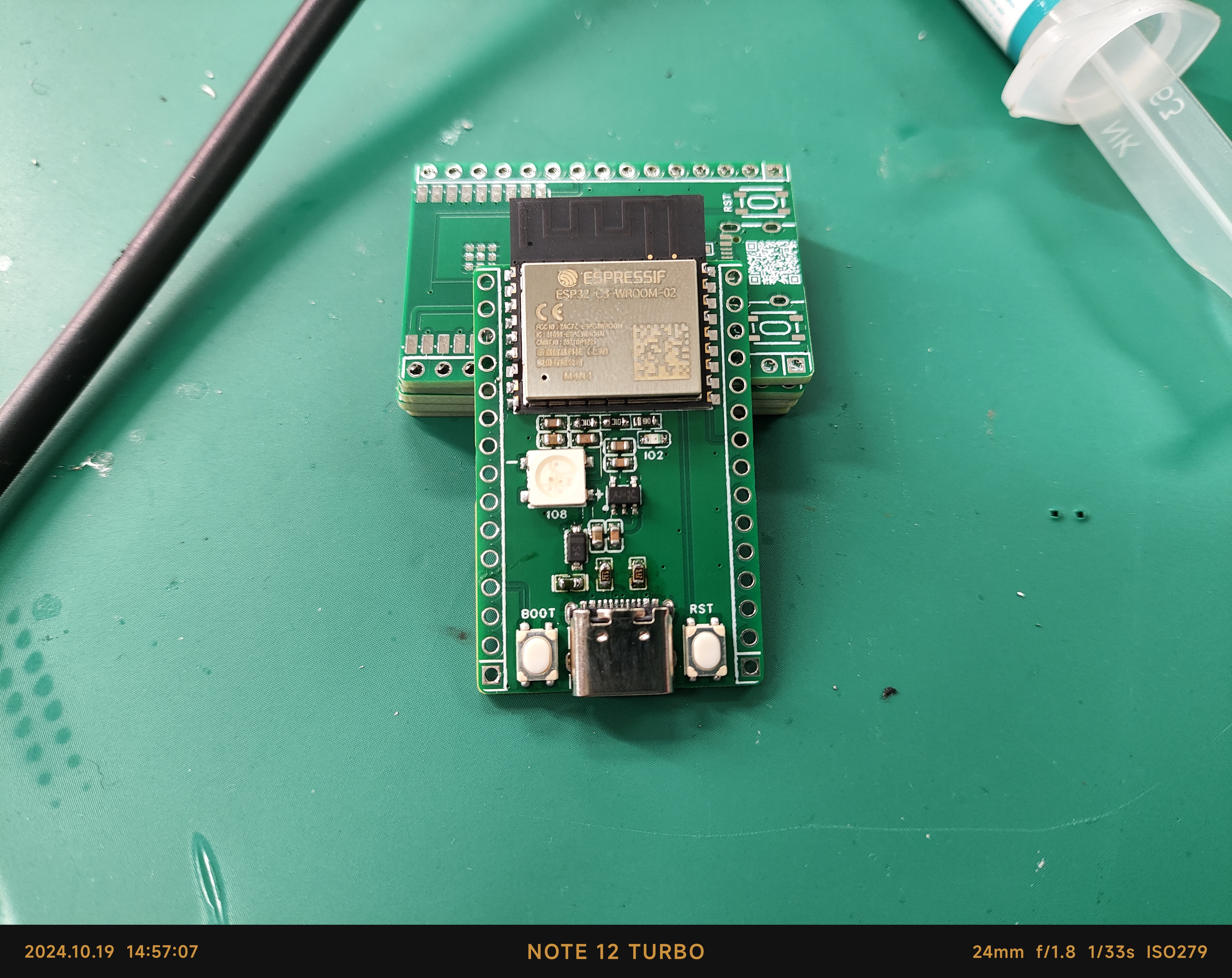
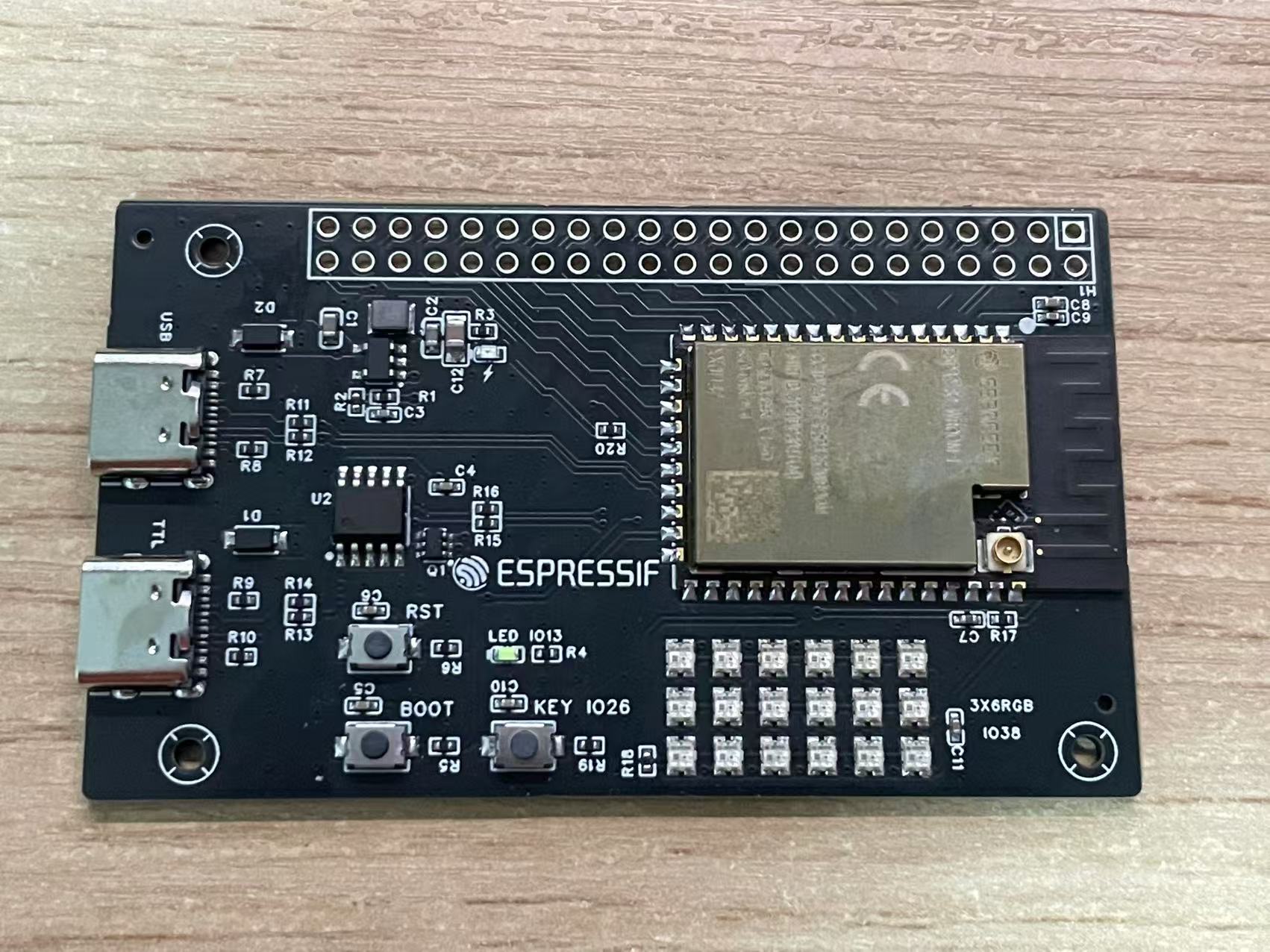
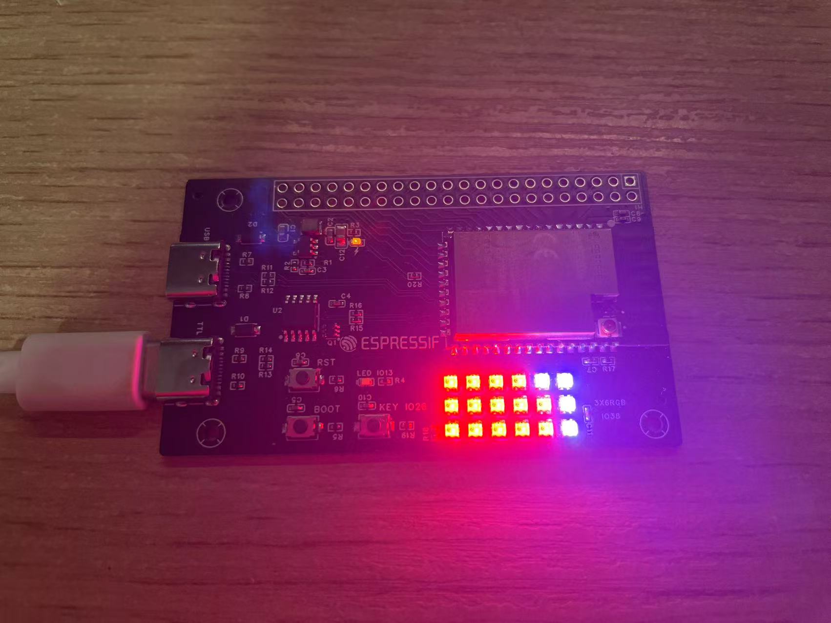
Replica ESP32-C3-DevKitC-02
Replica Espressif ESP32-C3-DevKitC-02 development board
This is a replica of Espressif's ESP32-C3-DevKitC-02 development board, with dimensions and definitions identical to the original. It also uses a 0603 package for easy manual soldering.
Schematic reference source: [Espressif ESP32-C3-DevKitC-02](https://docs.espressif.com/projects/esp-dev-kits/zh_CN/latest/esp32c3/esp32-c3-devkitc-02/index.html)
![IMG_20241019_145707.jpg]
![IMG_20241019_145613.jpg]

10.28 Update: Fixed a silkscreen error; this does not affect actual use.
VID_20241019_150009.mp4
VID_20241019_154653.mp4
PDF_Replica ESP32-C3-DevKitC-02.zip
Altium_Replica ESP32-C3-DevKitC-02.zip
PADS_Replica ESP32-C3-DevKitC-02.zip
BOM_Replica ESP32-C3-DevKitC-02.xlsx
91561
A step-down module based on TPS5450 to convert 10V~31V to 5V.
The market offers a wide variety of power supply modules, with inconsistent quality and a high failure rate. Therefore, it is necessary to design a suitable DC-DC power supply module.
The TPS5450 is a high-output-current PWM converter integrating a low-resistance, high-side N-channel MOSFET. The board, featuring the listed characteristics, also includes a high-performance voltage error amplifier (providing high regulation accuracy under transient conditions), an undervoltage lockout circuit (to prevent startup before the input voltage reaches 5.5V), an internally integrated slow-start circuit (to limit inrush current), and a voltage feedforward circuit (to improve transient response).
The input voltage range is 10V to 31V,
and the output voltage is 5V.
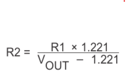
Using the calculated formula, R1=15.8K and R2=5.1K, the output voltage is made equal to 5V.
Output accuracy: No-load output 5.00%,
Full-load output 4.99%. The
output accuracy meets design requirements
. High-frequency electrolytic capacitors and TVS converters help improve dynamic response.
This buck module's ripple under load is basically within requirements, not exceeding 60mV.
The conversion efficiency fluctuates around 85% at various output currents.
PDF_10V/31V to 5V step-down module based on TPS5450.zip
Altium_10V/31V to 5V step-down module based on TPS5450.zip
PADS_TPS5450-based 10V/31V to 5V step-down module.zip
BOM_Based on TPS5450, implementing a 10V/31V to 5V step-down module.xlsx
91562
ESP32-S2 Development Board
ESP32-S2-WROVER-I Development Board
The ESP32-S2-WROVER-I development board exposes all I/O pins and adds 3x6 WS2812B RGB LEDs.

PDF_ESP32-S2 Development Board.zip
Altium_ESP32-S2 development board.zip
PADS_ESP32-S2 Development Board.zip
BOM_ESP32-S2 Development Board.xlsx
91563
LED light panel
This introductory project helps children become familiar with the use of JLCPCB EDA.
1. Introduction:
Are you ready to begin learning hardware circuits? Hardware learning is inseparable from PCB design, so learning to use JLCPCB EDA for PCB layout is essential. Starting with a simple LED circuit, you will learn some basic usage methods of the JLCPCB EDA editor, PCB circuit design, and PCB board fabrication, etc.
2. Schematic: The schematic
uses three LEDs connected in a common cathode configuration, using a header pin as the power input. When the input is high, the LED conducts. The header pin can be connected to the development board to create an LED running light effect using a microcontroller.
3. PCB and Soldering:
When designing the board outline, you can import DXF files to make the outline more than just a square shape. You can add your favorite silkscreen or images to the board; you can also open windows to make the pattern silver for a more sophisticated look.
Components are very easy to find: three free LEDs, three free resistors, and one header pin. Soldering may be difficult for beginners, but the circuit content is simple and the soldering difficulty is low, making it very suitable for beginners.
dfe3f33b5ee7515da839ce9c896d7903.mp4
c2f80915044043a74ddb40de8d63dab2.mp4
PDF_LED Light Board.zip
Altium_LED Light Board.zip
PADS_LED Light Board.zip
BOM_LED Lighting Panel.xlsx
91564
electronic


 京公网安备 11010802033920号

 10121750-2304171LF


