1. Main Controller Introduction:
The CH32V30x series is an industrial-grade general-purpose microcontroller designed based on 32-bit RISC-V by WCH (Qinheng Microelectronics). It features a hardware stack area and fast interrupt entry points, significantly improving interrupt response speed compared to standard RISC-V. The CH32V303 series is equipped with a V4F core. It incorporates a single-precision floating-point instruction set, expands the stack area, and offers higher computational performance. It also expands the number of UART serial ports to 8 and motor timers to 4.
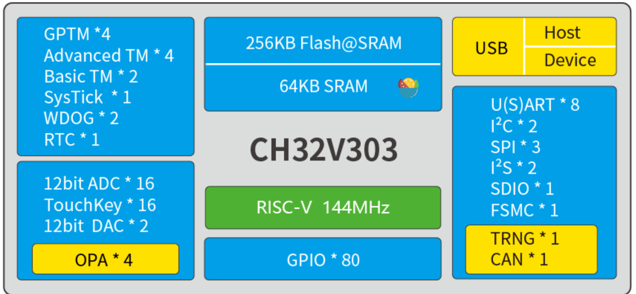
The system main frequency of up to 144MHz
supports single-cycle multiplication and hardware division, and supports hardware floating-point operation (FPU).
Qingke RISC-V general-purpose series - Nanjing Qinheng Microelectronics Co., Ltd. (wch.cn)
This chip has strong processing performance, low cost (5 RMB shipping included on Taobao), large RAM and FLASH space, and few counterfeit products, making it very suitable for low-cost FOC controllers.
The reason for not using v305/7 is that the high-speed USB and Ethernet functions added by 305/7 are unnecessary and significantly more expensive; however, the code is basically compatible.
2. Project Introduction:
Current Acquisition: Three-phase current acquisition; a differential sampling circuit is built using the CH32V303 on-chip op-amp, saving the need for a dedicated op-amp. One op-amp is used to output a 1.65V reference voltage.
Dual motor encoder interfaces: one IIC and one SPI, which can use different encoders, such as AS5600 and AS5047; especially preventing IIC bugs in the 32 series.
Operation: Multiple buttons, 1 encoder (plug-in encoder module for easy removal after board failure)
Display: Can be equipped with 1 IIC OLED display
Power supply: Supports 5~16V power supply
3.
Current sampling design: Since an on-chip op-amp is used, the amplification factor is adjusted by external resistors. Due to the small resistance value, the input impedance is small. Therefore, the 1.65V reference voltage needs to be output by an op-amp forming a voltage follower. Three resistors are used for sampling because the remaining op-amp is used.
Adjusting the amplification factor: Amplification factor calculation: When R5=R15, R8=R11, Vo = (R8/R5)*Vi. As shown in the figure, the amplification factor is 12.2. Therefore, the corresponding resistance value is adjusted to adjust the amplification factor.

Reference voltage: Since the motor current being sampled is a sine wave, it is necessary to sample a value with the opposite direction and the same amplitude; the ADC cannot do this; after using a differential amplifier circuit with a 1.65V bias, the AC voltage to be sampled can be mapped to a positive voltage range of 0~3.3V.
Sampling resistor: The maximum current that can be sampled is Imax = 1.65 / (amplification factor) / (sampling resistor). The larger the sampling resistor, the simpler the debugging. A 50mR resistor is actually used. MOSFET selection for
the lower sampling principle : Only the TO-252 package is used in the design. Many MOSFETs are available, but the NCE3080 is used due to its low cost. Download and debugging: A WCH debugger must be used: WCHLINK, WCHLINK-E, etc. (10 RMB including shipping on Taobao, E version is faster at 18 RMB; both support DAPLink and debugging ARM microcontrollers such as STM32). The current project is an optimization of the previous version. Due to minor changes, this version is not verified. A new version is being set up and verified. 4. The software uses FreeRTOS and references the DGM project, only implementing the current loop, which is no longer intended; this is just a starting point.


 京公网安备 11010802033920号

 131-6701-306


