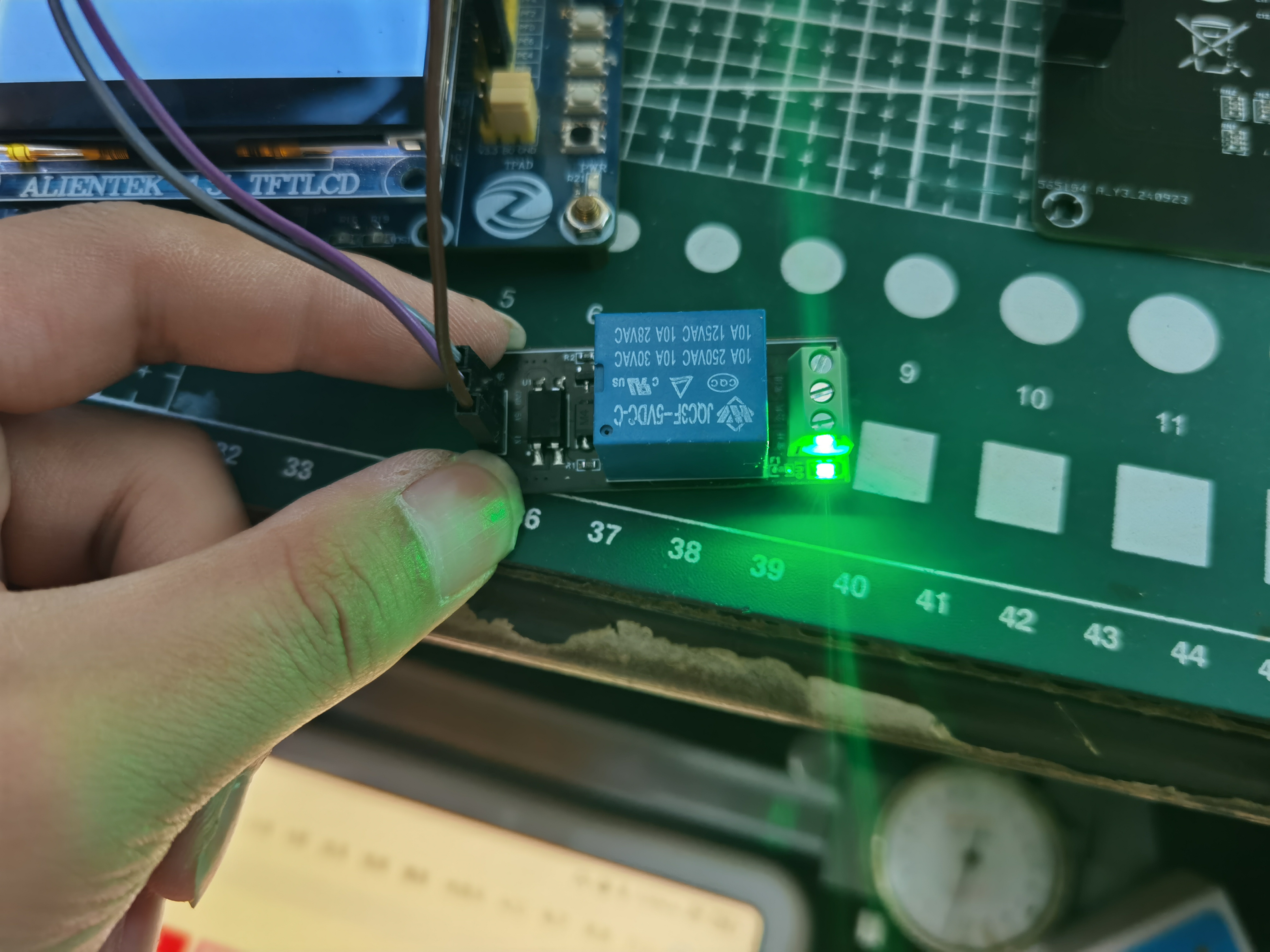
The module has been verified and can be used directly.
The module includes an EL817 optocoupler for isolation.

PDF_5V Optocoupler-Isolated Relay.zip
Altium_5V with optocoupler-isolated relay.zip
PADS_5V Optocoupler-Isolated Relay.zip
BOM_5V with optocoupler isolation relay.xlsx
91896
J-Link OB-RA4M2_V1.1, All-in-One OB
J-Link OB-RA4M2 is an OB debugger that supports most kernel architecture chips on the market.
Function Description:
1. Supports most core architecture chips on the market;
2. Supports SWD and JTAG;

3. Supports VCOM serial port function;
4. Includes 1-channel signal status indicator.
Hardware: 1.
PCB 3D Preview:


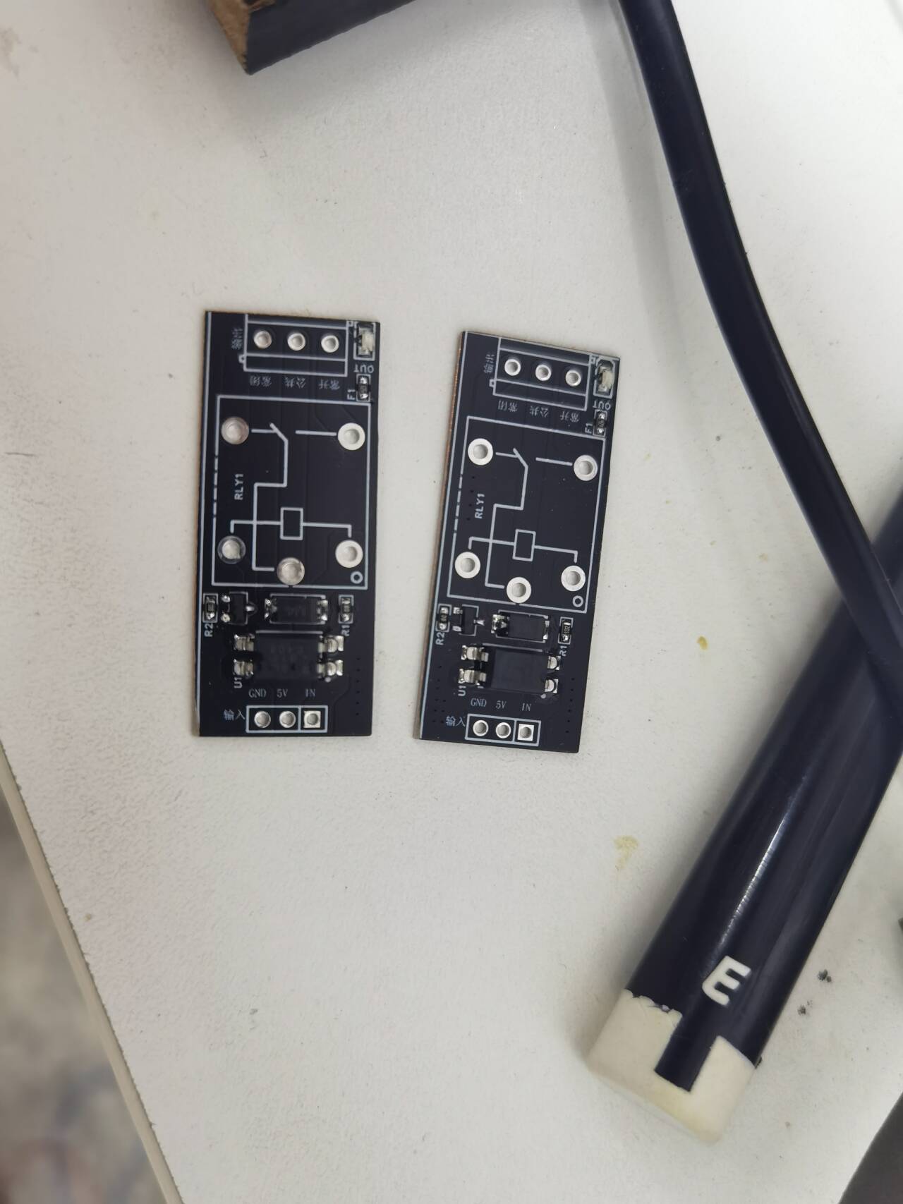
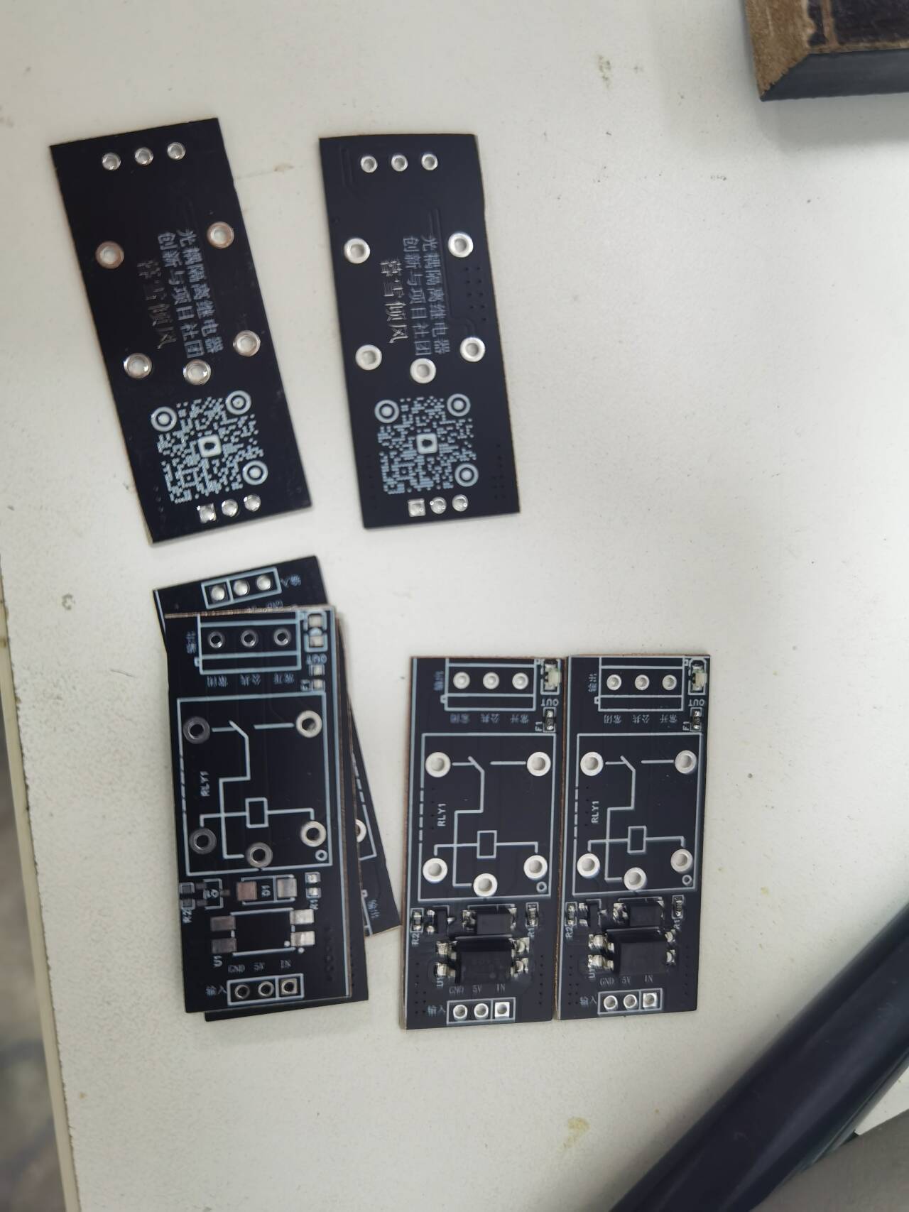
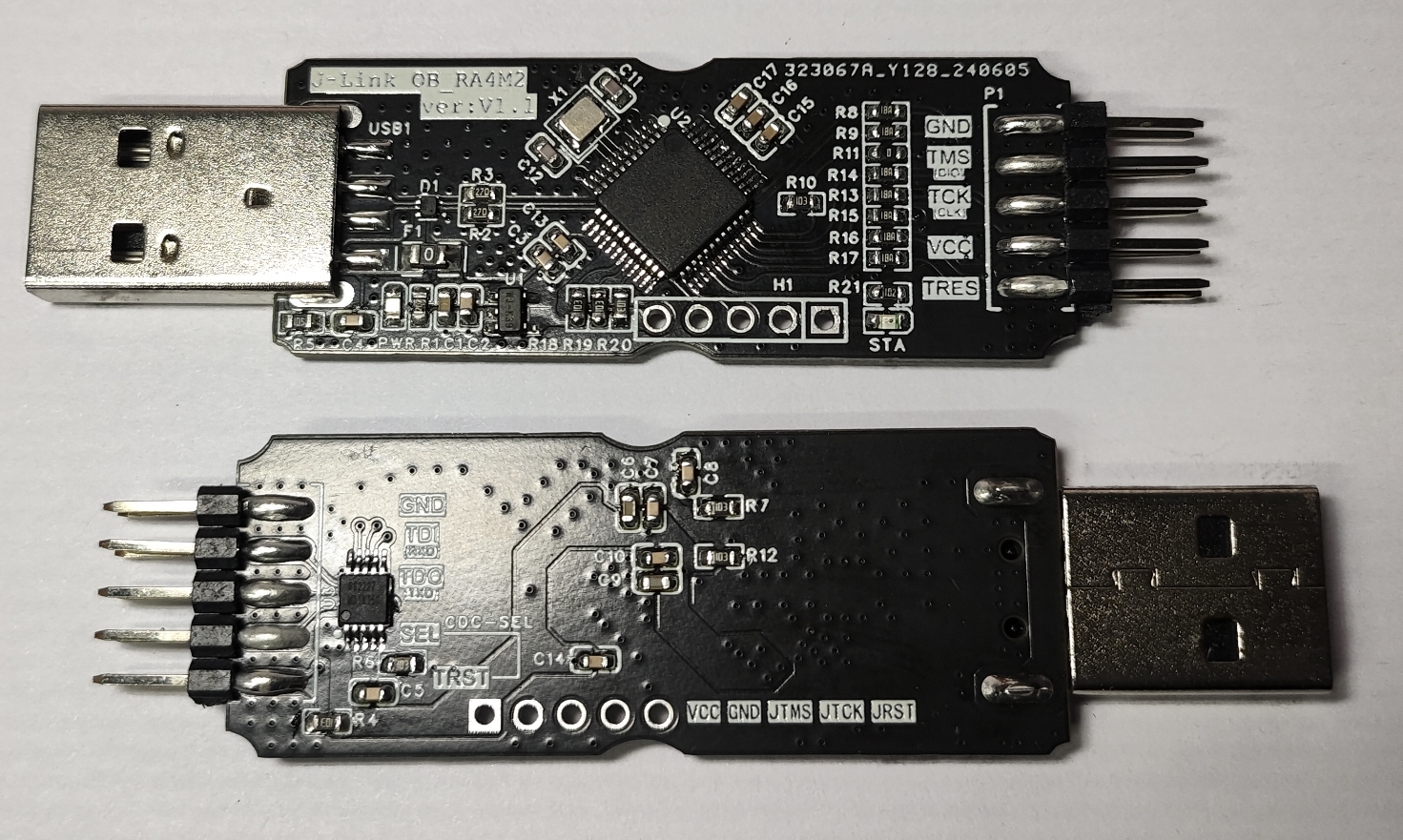
2. PCB Physical Image
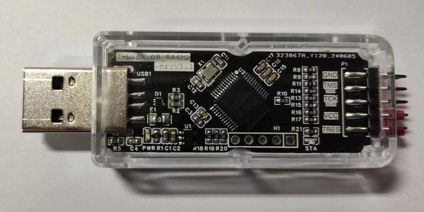
3. Finished Product Image
Software:
1. Firmware Download
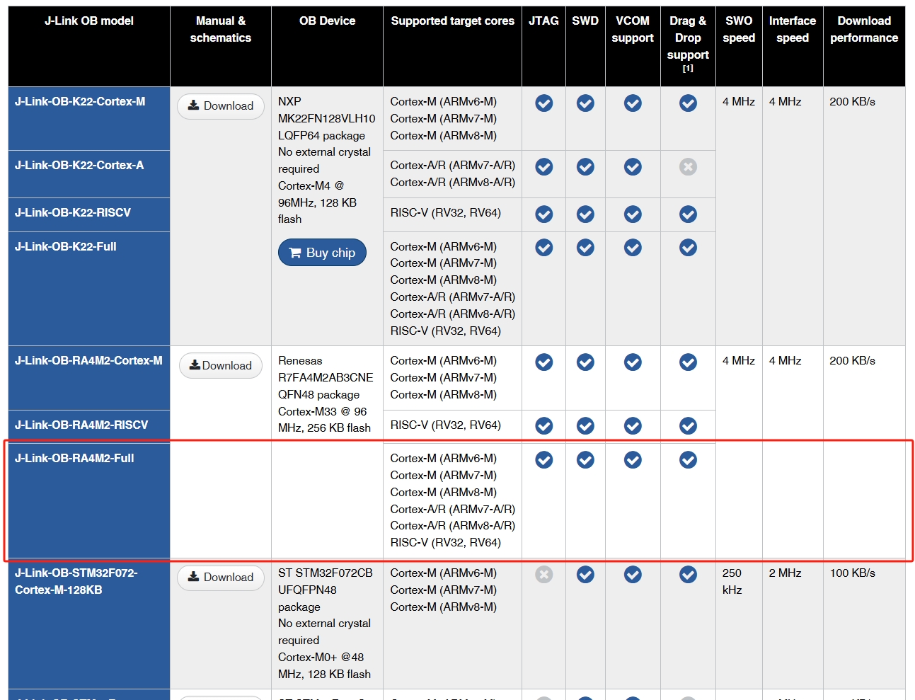
Firmware loading is somewhat special and requires certain modifications to download. This OB is powerful (supports a wide range of cores), which is its advantage, but also its "disadvantage"; as the saying goes, "a doctor cannot heal himself," often the more powerful it is, the more difficult it is to maintain when problems arise. You will find that previous JLink or OB debuggers could not download firmware to it because its main controller is R7FA4M2AB3CFL, an Arm® Cortex®-M33 Core, Armv8-M architecture MCU. If your JLink or OB debugger does not support the Armv8-M architecture, then you will not be able to download firmware, unless you have a Renesas dedicated downloader, which is a different story.
To solve this tricky problem, I collaborated with user O2C14. He provided the modified files, and I conducted hardware compatibility tests, finally resolving the issue. According to his description, the original JLink or OB supports downloading Armv8-M architecture chips, but the JFlash software imposed restrictions. The solution was to modify the software, specifically modifying the relevant files to enable this architecture. I didn't delve into the exact implementation, but he provided a modified file, which I used to replace the existing one. The general method involves modifying the JLink_x64.dll file to support Armv8-M architecture chip downloads. The attached JLink_x64.dll file is modified from JFlash-V7.94e. Therefore, if you want to download firmware using a debugger that doesn't support this architecture, you can install JFlash-V7.94e and replace the original dll file to support firmware downloads. (Special Note: The DLL only modifies relevant restrictions and does not make other modifications. It does not contain plugins or other elements, so you can download it with confidence. However, we do not guarantee that replacing this file will not cause software crashes or other unknown problems. Neither I nor the original author assume any risk of unknown problems arising from replacing this file. By using it, you agree to the above statement and are willing to bear the risks involved. Therefore, please back up the original file for future use. Thank you.) The original version does not support the following:

After replacing the DLL file, the firmware download is successful:
2. SN Modification:
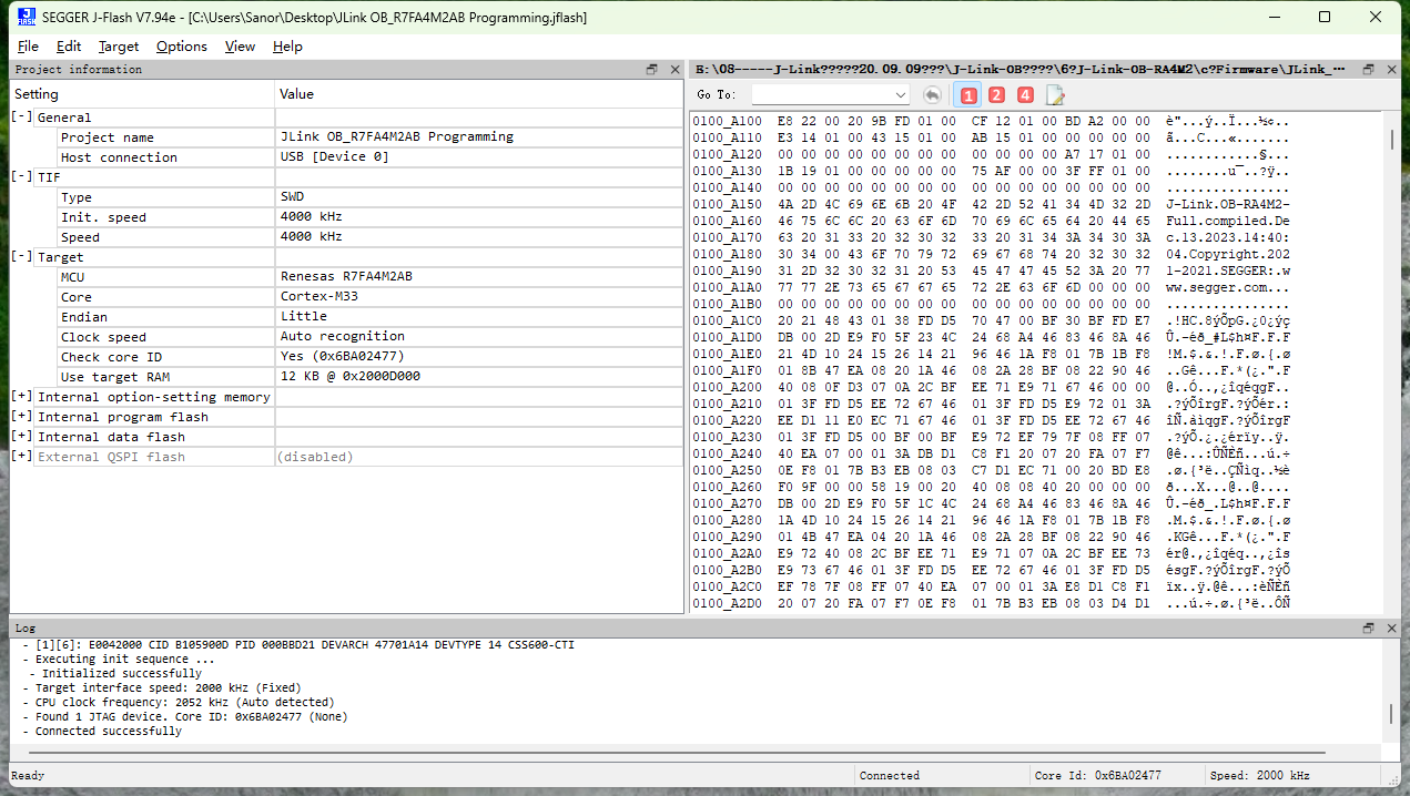
Based on my personal testing, the original firmware (excluding SN and Licenses) only supports one command to modify the firmware, i.e., either modify the SN once or add a License; however, this does not meet our needs. Through comparative research, we found that the SN address is located at firmware address 0x6000, while the License starting address is located at 0x6020, as shown in the figure below:

The SN encoding rule is the hexadecimal number corresponding to the decimal SN, taking the first 2 to 3 digits as the prefix. As shown in the image above, the SN is 23121301, corresponding to the hexadecimal number 160CD95. Each byte is stored in a group in the address, using little-endian mode, taking the first two digits 23 as the prefix. Therefore, the data represented in the address is: 95 CD 60 01 (the high-order byte is stored at the high address). (PS: This is my personal understanding; please forgive any inaccuracies or omissions). Understanding the SN encoding rules gives us a clue as to how to modify the SN and where to start.
Why modify the SN? Of course, it's to differentiate between different links or for personalization, since everyone may want to set a different SN. Then some people ask, why specifically mention SN modification? Can't it be modified via command (although only once)? The answer is that the original firmware only supports one command modification (a solution hasn't been found yet). Either modify the SN or add a License, but obviously neither of these can meet our needs. Even if you manually add Licenses first, once the original firmware has been modified, you cannot modify the firmware content again via command. While licenses are fixed, only the serial number (SN) varies from person to person.
Therefore, firmware for adding license information and the SN encoding rules are provided for DIY customization. To modify the SN, simply use the firmware provided in the attachment, convert it using a calculator according to the encoding rules, modify the SN content in the firmware, and finally download it to the debugger. Of course, if a better method is developed later, I will update it; if any friends discover one, I hope they can share it to benefit everyone.
3. VCOM Enabling
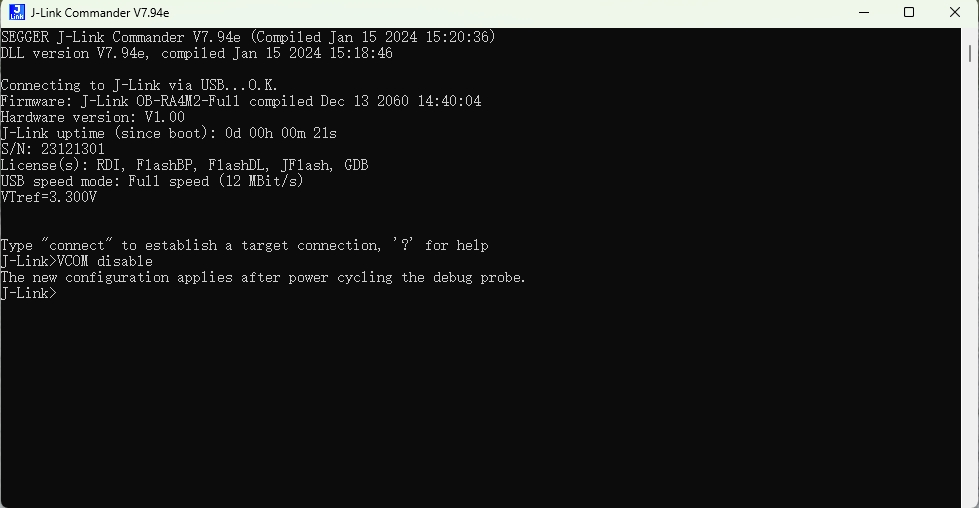
The original firmware has VCOM disabled by default. It can be enabled using the `VCOM enable` command or disabled using the `VCOM disable` command. This command can be executed repeatedly without limit, but the command only takes effect after the debugger is powered on again.
VCOM enable:


VCOM disable:

VCOM is enabled at address 0x8089 in the firmware. Below is a comparison of firmware information with VCOM disabled and enabled:
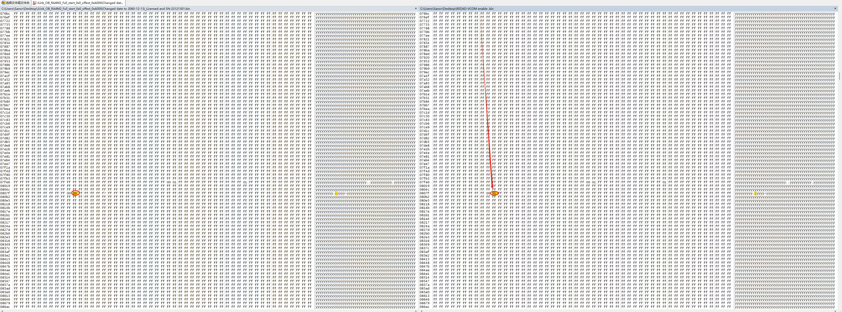
The firmware in the attachment has been modified to have VCOM enabled by default.
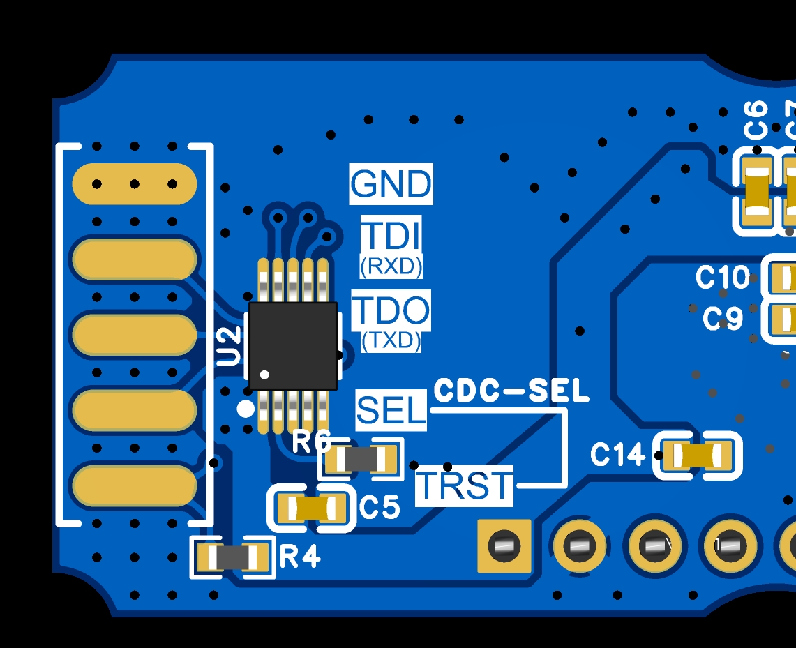
Special Note:
Virtual serial port CDC
enable is switched by shorting the header pins with an external jumper. By default, it uses the JTAG signal TDI and TDO paths when not connected; shorting SEL and TRST with the jumper switches to the serial port signal TXD and RXD paths.
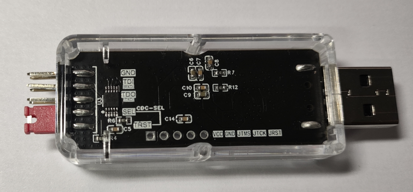
2. Firmware Download Special Note:
You need to use a 5-pin header to connect VCC, GND, JTMS, JTCK, and JRST to other OB debuggers simultaneously; otherwise, connection failures may occur.
Follow-up:
Follow-up 1: Upgradeable Firmware_24-09-23 Update
Preface
A couple of days ago, by chance, I saw an upgradeable OB-RARM2-Full firmware shared online by a guru, zhangjinke. The original address is: J-Link-OB-RA4M2. Those interested can go and check it out. So, out of curiosity, I downloaded it to take a look. After some testing, it is indeed upgradeable (with a built-in bootloader). So, let's update it.
Firmware Testing
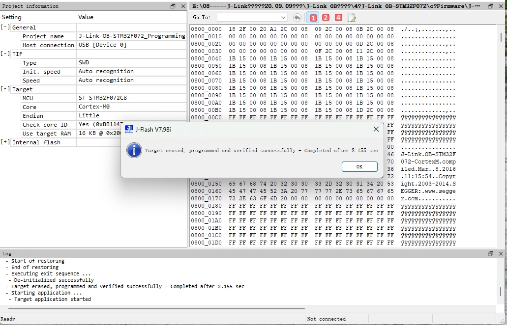
The firmware download is no different from before. It requires a downloader that supports the Cortex-M (ARMv8-M) core. You can use the previously modified files to replace them. However, another method has now emerged. Zhangjinke's GitHub page provides another firmware, "J-Link OB-STM32F072-128KB-CortexM," which, while not supporting automatic updates, does support Cortex-M (ARMv8-M) core architecture chips. Testing shows that downloading and supporting the RA4M2 processor is feasible, except for an update error when using a new driver. The following precautions should be taken when downloading:

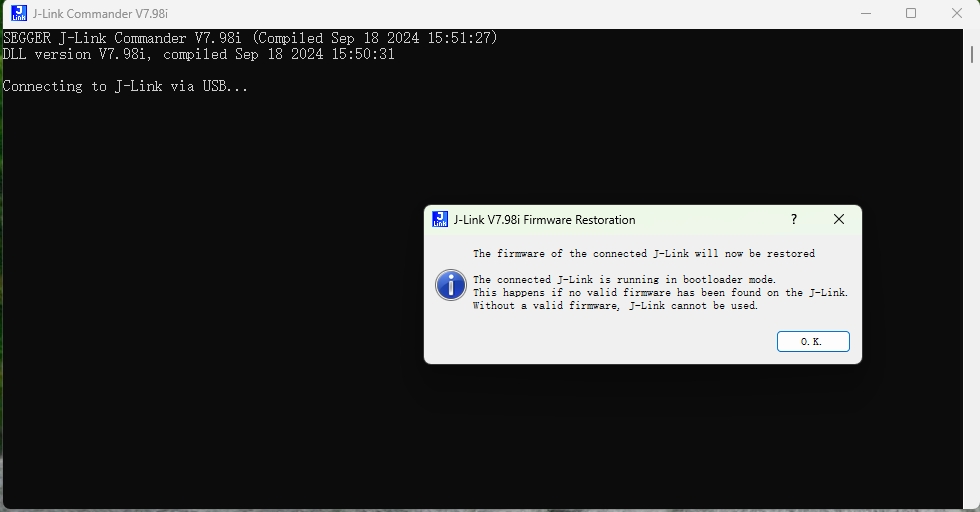
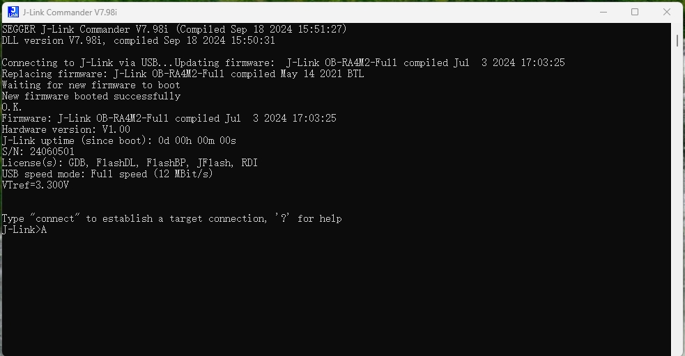
a) Firmware feasibility test. After the firmware download is complete, connect the debugger to the computer and open J-Link Commander. If a new firmware version (higher than J-Link OB-RA4M2-Full compiled Sep 13 2023 14:47:56) is available, it will indicate that the debugger is currently in bootloader mode. Confirm the update and enter bootloader mode; otherwise, enter bootloader mode directly, as shown below:
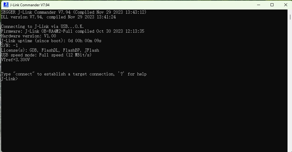
New firmware prompts bootloader mode; confirm the update and enter bootloader mode:


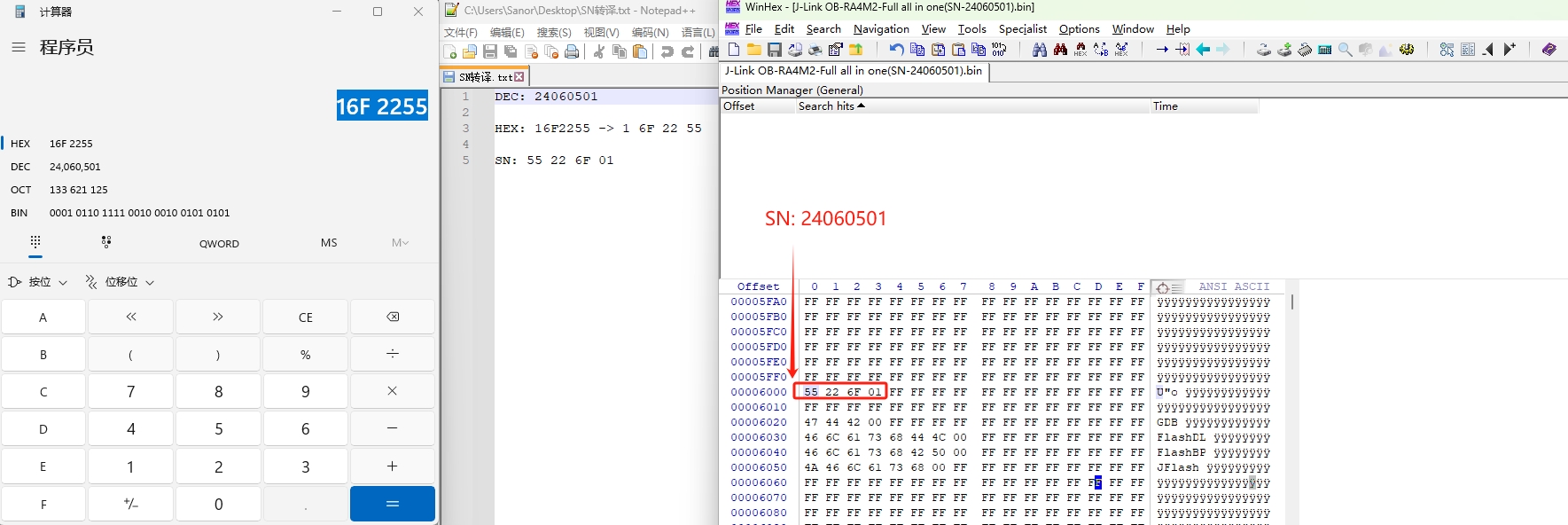
As you can see, the initial SN = -1, and a license has been added. Based on past experience, the old version of J-Link Commander could be used to add the SN via command, but this doesn't work. Therefore, the old method of manually adding the SN is necessary. The SN is stored in the chip's memory address in little-endian alignment, i.e., in hexadecimal format. Two numbers form one byte of data, stored in little-endian alignment. For example, the SN is 24060501, corresponding to the hexadecimal format 16F2255. According to the SN encoding rules, its storage method in memory is: 55 22 F6 01 (the low byte is stored at the low memory address, and the high byte at the high memory address), as shown below.

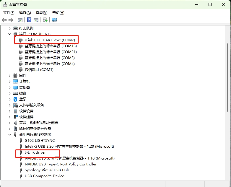
Next, let's test if the VCOM function is working properly. VCOM is enabled by default. If it is not enabled, you can use the command: VCOM enable in J-Link Commander. The VCOM test results are as follows:

Finally, let's test if the debugger's SWD download function is working properly. The test results are as follows:
That's all for this update. No further testing was done; interested readers can test it themselves. By the way, a bug has been discovered: occasionally after reconnecting, it prompts that the debugger is in bootloader mode, which can be entered after confirmation; a solution has not yet been found, and the specific cause and impact require further research and testing. Regarding the firmware, I will attach one or two firmware files with the serial number added. For the original firmware and other related materials, you can download them from the original author.
Update 2: Adding RDI_24-09-26.
The original firmware did not include the RDI-License, so it was manually added. The attachment contains a re-uploaded version with RDI information, as shown below:

[Disclaimer] To avoid copyright disputes, this OB debugger is for DIY enthusiasts or personal use only. Its creation and use must comply with relevant open-source licenses and may not be used for commercial purposes. Any violation will be the sole responsibility of the user. The final interpretation rights of the OB circuit and related source code firmware belong to Segger. I do not provide any form of technical support or service, nor do I assume any responsibility for any consequences arising from improper use. Please be aware of this disclaimer.
UM08040_JLinkOBRA4M2_Revision-1.pdf
JLink_OB_RA4M2_Full_start_0x0_offest_0xA000(Changed date to 2060-12-13)_Licenseed and SN-23121301.bin
JLink_OB_RA4M2_Full_start_0x0_offest_0xA000(Changed date to 2060-12-13)_Licenseed and SN-23121302.bin
JLink_x64 (V7.94e - modified dll to force support for ARMv8-M8.19 update).dll
JLink_OB_RA4M2_Full_start_0x0_offest_0xA000(Support firmware update)_Licenseed and SN-24060501.bin
JLink_OB_RA4M2_Full_start_0x0_offest_0xA000(Support firmware update)_Licenseed and SN-24060502.bin
Gerber_JLink-OB-RA4M2_PCB_2024-06-04.zip
PDF_J-Link OB-RA4M2_V1.1, All-in-One OB.zip
Altium_J-Link OB-RA4M2_V1.1, All-in-One OB.zip
PADS_J-Link OB-RA4M2_V1.1, All-in-One OB.zip
91897
Intelligent information collection system (network compatible)
This system integrates three types of gas concentration detection, temperature and humidity detection, and light intensity detection. It can connect to the internet to query the weather and transmit sensor data to an MQTT server for analysis.
Function Overview:
Multi-level menu with
indexing method for OLED menu;
three buttons for easy switching
; independent interfaces for each system function, saving system resources and
time; Information Acquisition
Software: Timer timing,
network time synchronization correction
, auxiliary calibration, saving system software resources;
Weather Information Acquisition: Connects to Gaode Weather's API interface
via ESP32's WiFi function to parse weather forecast JSON data; Environmental Information Acquisition: DHT11 temperature and humidity sensor reads temperature and humidity; BH1750 module reads light intensity; TVOC, CO2, and CH2O gas sensors read gas concentration.
PixPin_2024-10-07_20-02-42.png
Media 1.mp4
PixPin_2024-10-07_20-03-12.png
PixPin_2024-10-07_20-03-24.png
PDF_Intelligent Information Collection System (Network Connectable).zip
Altium_Intelligent Information Acquisition System (Network-enabled).zip
PADS_Intelligent Information Acquisition System (Network Connectable).zip
BOM_Intelligent Information Acquisition System (Network Connectable).xlsx
91899
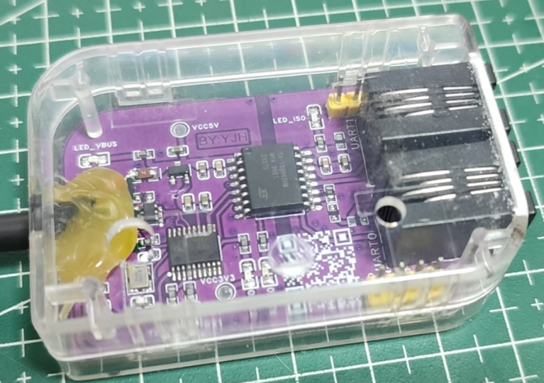
CH347T Dual-Channel High-Speed Isolated Serial Port
A dual-channel high-speed serial port module based on the CH347 high-speed USB adapter chip, supporting level conversion and input/output protection.
This project has been verified
. Key features include:
1. A high-speed USB adapter chip (CH347) converts the output to two high-speed serial ports, solving the problem of connecting multiple serial port modules during debugging of multi-chip embedded devices.
2. Version V1 uses the TXB0104 bidirectional level converter chip to achieve various serial port output level conversions, supporting 1.8, 2.5, and 3.3 GHz serial port levels, adapting to various embedded chips.
3. Output terminals can be soldered with 2.54mm header pins or directly wired to meet various needs.
4. Both USB inputs (D+, D-) and output terminals (TX, RX) are protected, significantly improving durability and stability.
5. A TYPE-C interface allows for easy extension via a mobile phone data cable (I have a lot of data cables, so I'll use up my inventory!).
6. Version V2 uses a digital isolator with power isolation to achieve complete isolation between the device's serial port and power supply (not because ISOW7742 is too expensive, but because domestic options are more cost-effective). 7. Version
V2's form factor is based on the CC-Debugger's casing design, which can be directly applied without additional design.
Core Architecture (Pure Hardware)
: USB to Serial Chip: CH347
V1; Level
Shifter Chip: TXB0104
V2 (Recommended);
Dual-Channel Chip with Power Isolation: CA-IS3642HW
WeChat image_20231028215043.jpg
C2890053_Digital Isolator (with power supply)_CA-IS3642HW_Datasheet_CHIPANALOG (川土微) Digital Isolator Datasheet.PDF
PDF_CH347T Dual-Channel High-Speed Isolated Serial Port.zip
Altium_CH347T Dual-Channel High-Speed Isolated Serial Port.zip
PADS_CH347T Dual-Channel High-Speed Isolated Serial Port.zip
BOM_CH347T Dual-Channel High-Speed Isolated Serial Port.xlsx
91900
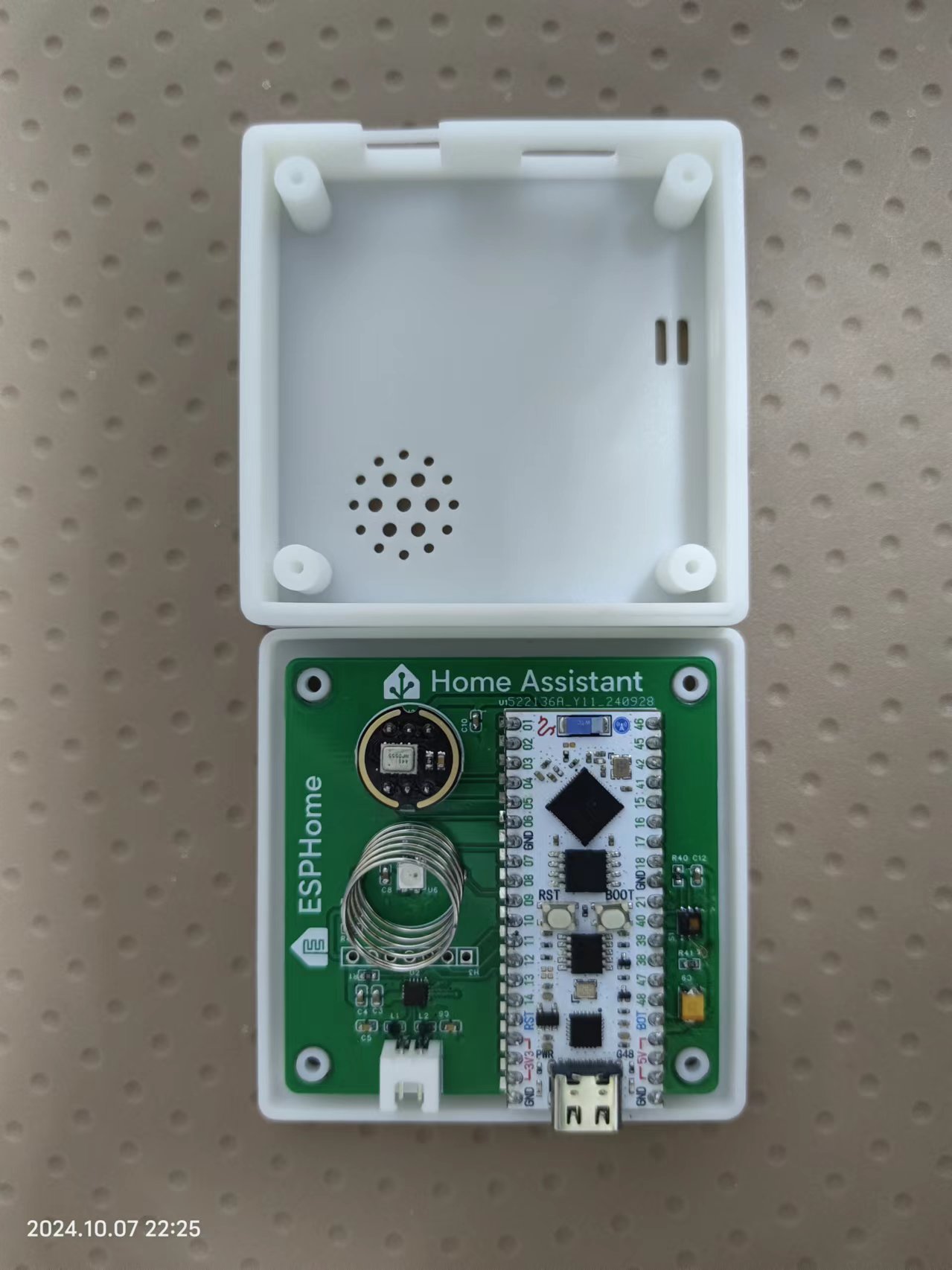
Homeassistant Multifunctional AI Voice Assistant
Using the JLCPCB ESP32S3 development board, create a Home Assistant AI voice assistant with features including Chinese wake word, TTS, HA offline STT, environmental detection, and integration with AI large-scale models to control smart home devices.
Video Link: Bilibili Video -- HomeAssistant AI Voice Assistant Project Introduction
Based on JLCPCB ESP32 Development Board This project is based on the JLCPCB ESP32S3 development board and implements a HomeAssistant AI voice assistant that integrates wake word, TTS, STT, environmental detection, and AI large-scale model control for smart home devices. Project Functions This design is based on the JLCPCB ESP32 development board and features a HomeAssistant AI voice assistant with one microphone supporting wake word activation and conversation end detection; one speaker for voice playback; one RGB light to display offline, online/idle, wake-up, voice acquisition, thinking, and voice reply status; one touch button to toggle microphone mute (the touch spring is disabled after adding a casing); and an ambient temperature and humidity detector. Project parameters: This design allows for customizable Chinese wake-up words; this design allows for customizable sentence responses and execution of related commands; this design can mute the microphone to avoid accidental wake-up at night; it uses the HDC1080 fully digital temperature and humidity sensor, which has a wide temperature measurement range and can meet general needs; the software code is based on ESPhome programming, making it easy to get started quickly. Project code: https://github.com/JochenZhou/esphome-packages Thanks to the following project authors: Original ESPhome code : https://github.com/tronikos/esphome-packages/tree/main Speech recognition repository: https://github.com/yaming116/sherpa-onnx-asr Integration: https://github.com/yaming116/home-assistant-fun-asr Add-ons: https://github.com/knoop7/hassio-addons Chinese wake-up words Add-ons: https://github.com/rhasspy/hassio-addons. For specific integration methods, please refer to the documentation at the links above. Notes: ESPhome compilation and installation requires a GitHub connection and a VPN. The wake word may sometimes malfunction under a VPN, so it is recommended to disable the VPN after installation. Whether or not you need to disable it is up to you to test. Touch spring malfunction after adding a case. Figure 1: Actual product image .
WeChat_20241008094146.mp4
lc-esp32s3r8n8-va.yaml
PDF_Homeassistant Multifunctional AI Voice Assistant.zip
Altium_Homeassistant Multifunctional AI Voice Assistant.zip
PADS_Homeassistant Multifunctional AI Voice Assistant.zip
BOM_Homeassistant Multifunctional AI Voice Assistant.xlsx
91903
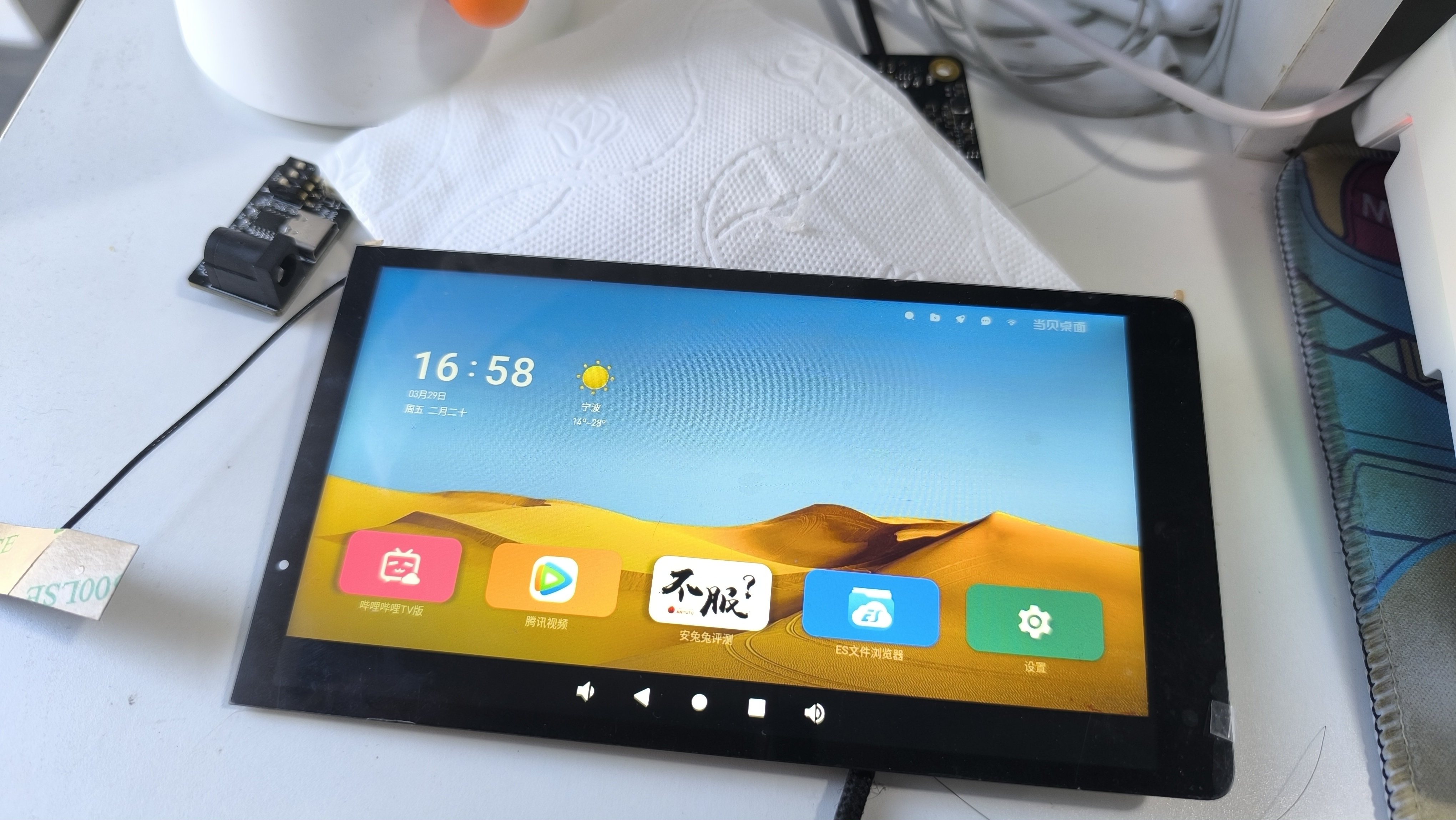
Taishanpai - 6-inch Cat Screen Adapter Board
Adapter board for Taishanpai - 6-inch cat screen
The adapter board for the Taishanpai 6-inch cat screen
has been modified with a redesigned package for easier manual soldering.
The board area has been reduced, and
the connector positions correspond to both the screen and Taishanpai orientations. For connecting to the Taishanpai, you can choose between a 31-pin 0.3mm pitch ribbon cable or a 6-pin 0.5mm pitch ribbon cable.
6-inch 720*1280 resolution, with touch, 0-1-2-clk, 49.9 RMB including shipping. (Actual prices may vary; please refer to the actual order.) The screen display and touch functionality are now successfully driver-driven. You can directly replace the files according to the documentation.
Baidu Cloud screen data updates || Taishanpai driver updates || Baidu Cloud screen/shell 3D model/test firmware || Quark screen test firmware
|| Taobao screen purchase link || Taobao BTB connector purchase link || Taobao 31-pin 0.3mm pitch ribbon cable purchase link. Connectors
are optional; you can also purchase a ready-made adapter board, which the seller has already made. To place an order, please message the seller with the username "樱猫" (Yingmao). A matching stand and
screen driver modification
will be included. To modify the screen driver: Download the attached file and extract it. Place the file `/tspi-disp-6-master/tspi-rk3566-dsi-v10.dtsi` in the following folder and replace the existing file:
`/tspi_linux_sdk/ Release/kernel/arch/arm64/boot/dts/rockchip/tspi-rk3566-dsi-v10.dtsi`.
This replacement file already has the modified driver code for screen initialization and backlight control, etc., so no further manual modification is needed.
Locate the file tspi-rk3566-user-v10-linux.dts in the same folder, open and edit it to enable the DSI screen; otherwise, the MIPI screen will not display.
// [On/Off] MIPI display screen configuration. Users can copy their own screen based on this. Note that EDP and MIPI screens are mutually exclusive because they share a VOP. If you need simultaneous display, modify #include "tspi-rk3566-dsi-v10.dtsi".
Touch screen driver modification:
Copy the /tspi-disp-6-master/gt9xx folder from the attachment to the following location and replace
/tspi_linux_sdk/Release/kernel/drivers/input/touchscreen/gt9xx.
Then recompile the kernel separately and flash boot.img separately. After a few minutes of system initialization, the screen can be used.
Without modification, the touch screen can still be used, but the displacement will be inaccurate.
The Taishanpai comes with an Android system. For screen testing, you can directly flash the factory-installed system into the attached boot.img. A Linux version is also provided; both share the same boot.img.
The boot.img and complete firmware can be downloaded from Baidu Cloud or Quark.
To rotate the screen by 90 degrees:
In the file `/tspi_android_sdk/device/rockchip/common/BoardConfig.mk`, modify the following:
`#rotate screen to 0, 90, 180, 270 #0: ROTATION_NONE ORIENTATION_0 : 0 #90: ROTATION_RIGHT ORIENTATION_90 : 90 #180: ROTATION_DOWN ORIENTATION_180: 180 #270: ROTATION_LEFT ORIENTATION_270: 270 # For Recovery Rotation TARGET_RECOVERY_DEFAULT_ROTATION := ROTATION_RIGHT //Screen rotation 90 degrees
# For Surface` Flinger Rotation SF_PRIMARY_DISPLAY_ORIENTATION := 90 // Rotate the screen by 90 degrees.
Note: The highlighted part needs to be changed to :=, otherwise, if it's still !=, the rotation won't work.
Next, you need to modify the touch screen so that it also rotates 90 degrees. Otherwise, the screen orientation will change, but the touch screen won't work correctly.
Search for 911 in the file /tspi_linux_sdk/Release/kernel/drivers/input/touchscreen/gt9xx/gt9xx.c, and change the content to the following:
else if (val == 911) { m89or101 = FALSE; bgt911 = TRUE; gtp_change_x2y = FALSE; // Whether to swap the x-axis and y-axis gtp_x_reverse = TRUE; // Whether to flip the x-axis gtp_y_reverse = FALSE; // Whether to flip the y-axis }
Then recompile Android and the kernel.
To modify the startup logo image:
The Taishanpai startup logo image file is a 470*654 pixel BMP file. It needs to be edited and exported using Photoshop or other image editing software according to the requirements.
Note: Simply changing the file extension will not work and will cause compilation errors. Place the modified image file in `/tspi_android_sdk/Release/kernel/` and replace the original file. If you need to rotate
`logo_kernel.bmp` or `logo.bmp`
by 90 degrees, you can rotate the file directly during editing and then export and replace it.
Currently, adding `logo,rotate = ;` as suggested by the search results is ineffective.
Pre-installed APKs:
After compiling Android, check the directories required for adding applications. In the command prompt, type: `get_build_var TARGET_DEVICE_DIR`. This is usually located at `/tspi_android_sdk/device/rockchip/rk356x/rk3566_tspi/`. Create three folders in this directory: `preinstall` (for non-uninstallable applications), `preinstall_del_forever` (for uninstallable applications), and `preinstall_del` (to restore factory settings after uninstallation). Place the APKs you want to pre-install into the corresponding newly created folders. You don't need to manually add the .mk files. Then, recompile Android separately. If all goes well, the corresponding APK folder and .mk file will be automatically generated in the newly created folders.
Files with corresponding names will also be automatically generated in the following directories .
Troubleshooting for the signature section of pre-installed applications in `/tspi_android_sdk_20230916/out/target/product/k3568_tspi/obj/APPS/` : For
issues like inconsistent side lines and screen jitter , modify the following section in the file `/tspi_linux_sdk/Release/kernel/ arch/arm64/boot/dts/rockchip/tspi-rk3566-dsi-v10.dtsi`: The issue might be caused by insufficient values. The correct values are: `hactive = ; hfront-porch = 8>; hback-porch = 8>; hsync-len = 16>; vactive = ; vfront-porch = 8>; vback-porch = 8>; vsync-len = 16>; ` Then recompile the kernel. Backlight only on, screen not on: This is usually caused by a poor solder joint on the screen adapter board. Resoldering will solve the problem; adding more flux can help. Note: Using a multimeter may be inaccurate because the poor solder joint is only a small gap preventing data transmission. When using a multimeter, the probe might completely close the gap, showing a connection during measurement, but disconnecting again after removing the meter. Backlight overheating: Under normal circumstances, the screen should not overheat. If it does, you can modify the backlight PWM control code in `/tspi_linux_sdk/Release/kernel/arch/arm64/boot/dts/rockchip/tspi-rk3566-dsi-v10.dtsi` to limit the current. The maximum screen current is 20mA; too high a current will cause the backlight to overheat or burn out. If burned out, the backlight must be removed and the LED chips replaced. The default maximum output of the Taishanpai is 110mA, limiting the maximum PWM value to 20/110*255≈46. Replacing the file provided by this website will resolve this issue. Backlight driver overheating/screen flickering: Under normal circumstances, the screen driver should not overheat; it should feel warm to the touch, not hot. Overheating is likely due to a short circuit in the backlight pins of the screen adapter board, causing a change in the parameters of the boost inductor in the backlight driver, resulting in overheating. This change in inductor value may affect the screen display, causing flickering even when all screen driver parameters are normal. Replacing the Taishanpai resolves the flickering. Both of these issues can be resolved by replacing the backlight driver inductor. The inductor needs to be a 1008 package, with an inductance of 10uH and a current rating of 800mA or higher. Below is a display demonstration:


Cat screen landscape display.mp4
6-inch Cat Screen Data.zip
PDF_Taishanpai - 6-inch Cat Screen Adapter Board.zip
Altium_Taishanpai-6-inch Cat Screen Adapter Board.zip
PADS_Taishanpai - 6-inch Cat Screen Adapter Board.zip
BOM_Taishanpai-6-inch Cat Screen Adapter Board.xlsx
91904
electronic


 京公网安备 11010802033920号

 09 67 000 5476


