The adapter board for the Taishanpai 6-inch cat screen
has been modified with a redesigned package for easier manual soldering.
The board area has been reduced, and
the connector positions correspond to both the screen and Taishanpai orientations. For connecting to the Taishanpai, you can choose between a 31-pin 0.3mm pitch ribbon cable or a 6-pin 0.5mm pitch ribbon cable.
6-inch 720*1280 resolution, with touch, 0-1-2-clk, 49.9 RMB including shipping. (Actual prices may vary; please refer to the actual order.) The screen display and touch functionality are now successfully driver-driven. You can directly replace the files according to the documentation.
Baidu Cloud screen data updates || Taishanpai driver updates || Baidu Cloud screen/shell 3D model/test firmware || Quark screen test firmware
|| Taobao screen purchase link || Taobao BTB connector purchase link || Taobao 31-pin 0.3mm pitch ribbon cable purchase link. Connectors
are optional; you can also purchase a ready-made adapter board, which the seller has already made. To place an order, please message the seller with the username "樱猫" (Yingmao). A matching stand and
screen driver modification
will be included. To modify the screen driver: Download the attached file and extract it. Place the file `/tspi-disp-6-master/tspi-rk3566-dsi-v10.dtsi` in the following folder and replace the existing file:
`/tspi_linux_sdk/ Release/kernel/arch/arm64/boot/dts/rockchip/tspi-rk3566-dsi-v10.dtsi`.
This replacement file already has the modified driver code for screen initialization and backlight control, etc., so no further manual modification is needed.
Locate the file tspi-rk3566-user-v10-linux.dts in the same folder, open and edit it to enable the DSI screen; otherwise, the MIPI screen will not display.
// [On/Off] MIPI display screen configuration. Users can copy their own screen based on this. Note that EDP and MIPI screens are mutually exclusive because they share a VOP. If you need simultaneous display, modify #include "tspi-rk3566-dsi-v10.dtsi".
Touch screen driver modification:
Copy the /tspi-disp-6-master/gt9xx folder from the attachment to the following location and replace
/tspi_linux_sdk/Release/kernel/drivers/input/touchscreen/gt9xx.
Then recompile the kernel separately and flash boot.img separately. After a few minutes of system initialization, the screen can be used.
Without modification, the touch screen can still be used, but the displacement will be inaccurate.
The Taishanpai comes with an Android system. For screen testing, you can directly flash the factory-installed system into the attached boot.img. A Linux version is also provided; both share the same boot.img.
The boot.img and complete firmware can be downloaded from Baidu Cloud or Quark.
To rotate the screen by 90 degrees:
In the file `/tspi_android_sdk/device/rockchip/common/BoardConfig.mk`, modify the following:
`#rotate screen to 0, 90, 180, 270 #0: ROTATION_NONE ORIENTATION_0 : 0 #90: ROTATION_RIGHT ORIENTATION_90 : 90 #180: ROTATION_DOWN ORIENTATION_180: 180 #270: ROTATION_LEFT ORIENTATION_270: 270 # For Recovery Rotation TARGET_RECOVERY_DEFAULT_ROTATION := ROTATION_RIGHT //Screen rotation 90 degrees
# For Surface` Flinger Rotation SF_PRIMARY_DISPLAY_ORIENTATION := 90 // Rotate the screen by 90 degrees.
Note: The highlighted part needs to be changed to :=, otherwise, if it's still !=, the rotation won't work.
Next, you need to modify the touch screen so that it also rotates 90 degrees. Otherwise, the screen orientation will change, but the touch screen won't work correctly.
Search for 911 in the file /tspi_linux_sdk/Release/kernel/drivers/input/touchscreen/gt9xx/gt9xx.c, and change the content to the following:
else if (val == 911) { m89or101 = FALSE; bgt911 = TRUE; gtp_change_x2y = FALSE; // Whether to swap the x-axis and y-axis gtp_x_reverse = TRUE; // Whether to flip the x-axis gtp_y_reverse = FALSE; // Whether to flip the y-axis }
Then recompile Android and the kernel.
To modify the startup logo image:
The Taishanpai startup logo image file is a 470*654 pixel BMP file. It needs to be edited and exported using Photoshop or other image editing software according to the requirements.
Note: Simply changing the file extension will not work and will cause compilation errors. Place the modified image file in `/tspi_android_sdk/Release/kernel/` and replace the original file. If you need to rotate
`logo_kernel.bmp` or `logo.bmp`
by 90 degrees, you can rotate the file directly during editing and then export and replace it.
Currently, adding `logo,rotate = ;` as suggested by the search results is ineffective.
Pre-installed APKs:
After compiling Android, check the directories required for adding applications. In the command prompt, type: `get_build_var TARGET_DEVICE_DIR`. This is usually located at `/tspi_android_sdk/device/rockchip/rk356x/rk3566_tspi/`. Create three folders in this directory: `preinstall` (for non-uninstallable applications), `preinstall_del_forever` (for uninstallable applications), and `preinstall_del` (to restore factory settings after uninstallation). Place the APKs you want to pre-install into the corresponding newly created folders. You don't need to manually add the .mk files. Then, recompile Android separately. If all goes well, the corresponding APK folder and .mk file will be automatically generated in the newly created folders.
Files with corresponding names will also be automatically generated in the following directories .
Troubleshooting for the signature section of pre-installed applications in `/tspi_android_sdk_20230916/out/target/product/k3568_tspi/obj/APPS/` : For
issues like inconsistent side lines and screen jitter , modify the following section in the file `/tspi_linux_sdk/Release/kernel/ arch/arm64/boot/dts/rockchip/tspi-rk3566-dsi-v10.dtsi`: The issue might be caused by insufficient values. The correct values are: `hactive = ; hfront-porch = 8>; hback-porch = 8>; hsync-len = 16>; vactive = ; vfront-porch = 8>; vback-porch = 8>; vsync-len = 16>; ` Then recompile the kernel. Backlight only on, screen not on: This is usually caused by a poor solder joint on the screen adapter board. Resoldering will solve the problem; adding more flux can help. Note: Using a multimeter may be inaccurate because the poor solder joint is only a small gap preventing data transmission. When using a multimeter, the probe might completely close the gap, showing a connection during measurement, but disconnecting again after removing the meter. Backlight overheating: Under normal circumstances, the screen should not overheat. If it does, you can modify the backlight PWM control code in `/tspi_linux_sdk/Release/kernel/arch/arm64/boot/dts/rockchip/tspi-rk3566-dsi-v10.dtsi` to limit the current. The maximum screen current is 20mA; too high a current will cause the backlight to overheat or burn out. If burned out, the backlight must be removed and the LED chips replaced. The default maximum output of the Taishanpai is 110mA, limiting the maximum PWM value to 20/110*255≈46. Replacing the file provided by this website will resolve this issue. Backlight driver overheating/screen flickering: Under normal circumstances, the screen driver should not overheat; it should feel warm to the touch, not hot. Overheating is likely due to a short circuit in the backlight pins of the screen adapter board, causing a change in the parameters of the boost inductor in the backlight driver, resulting in overheating. This change in inductor value may affect the screen display, causing flickering even when all screen driver parameters are normal. Replacing the Taishanpai resolves the flickering. Both of these issues can be resolved by replacing the backlight driver inductor. The inductor needs to be a 1008 package, with an inductance of 10uH and a current rating of 800mA or higher. Below is a display demonstration:

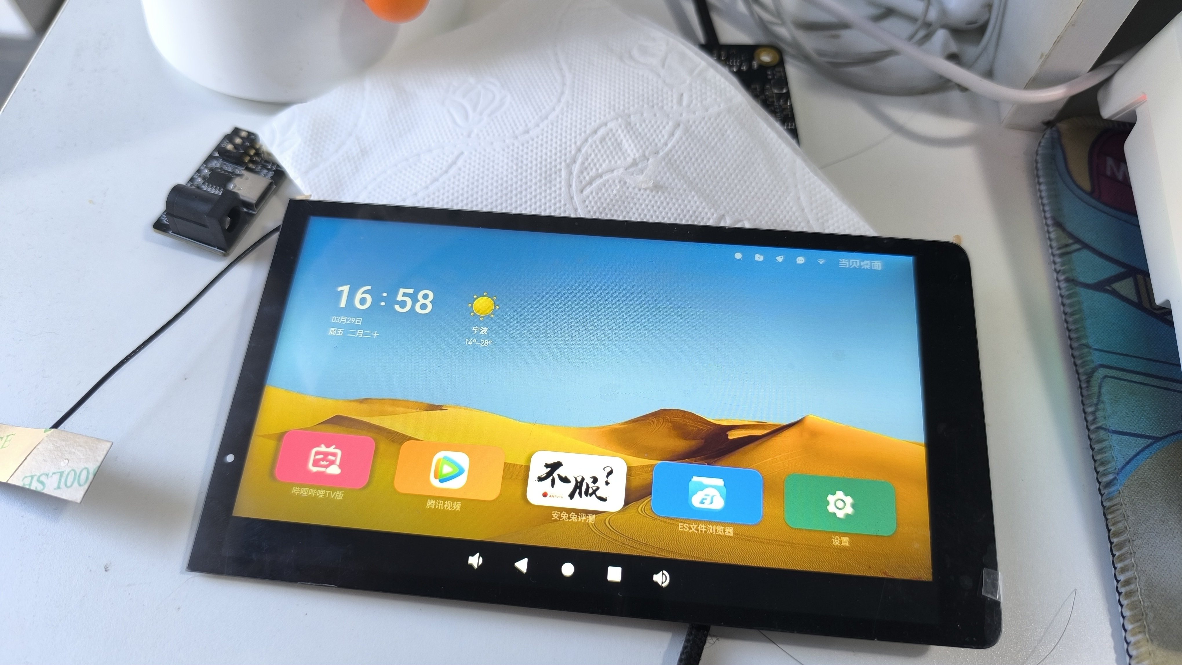


Cat screen landscape display.mp4
6-inch Cat Screen Data.zip
PDF_Taishanpai - 6-inch Cat Screen Adapter Board.zip
Altium_Taishanpai-6-inch Cat Screen Adapter Board.zip
PADS_Taishanpai - 6-inch Cat Screen Adapter Board.zip
BOM_Taishanpai-6-inch Cat Screen Adapter Board.xlsx
91904
electronic


 京公网安备 11010802033920号

 24C01SC-S


