Project Overview
This project is a simple RCL (
Resistance, Capacitance, and Inductance) meter. An RCL meter is an electronic test device used to measure resistance, capacitance, and inductance (RCL stands for Resistance, Capacitance, and Inductance). It is commonly used in electronic engineering and electrical testing to measure and analyze the electrical characteristics of electronic components. An RCL meter provides accurate measurements of resistance, capacitance, and inductance values, which is crucial for researching and developing new electronic devices, maintaining existing electronic systems, and troubleshooting.
Project Functions
The measurement functions of an RCL meter include, but are not limited to, voltage measurement, frequency measurement, open-circuit voltage correction, short-circuit voltage correction, resistance measurement, and capacitance/inductance measurement. These functions make the RCL meter an indispensable tool for electronic engineers and electrical technicians. By using an RCL meter, detailed information about the resistive, capacitive, and inductive components in a circuit can be obtained, which is essential for optimizing circuit design, improving equipment performance, and ensuring safe operation of equipment.
Furthermore, the use of an RCL meter involves several safety and maintenance considerations, such as proper grounding methods, the use of voltage and fuses, and proper placement of the instrument to avoid radio frequency interference. These safety measures aim to ensure the accuracy and safety of the testing process and prevent potential electrical hazards during testing.
In summary, the RCL meter is a versatile electronic test instrument that helps engineers and technicians better understand and optimize the performance of electronic systems by providing accurate resistance, capacitance, and inductance measurements. Meanwhile, the safety guidelines that must be followed when using an RCL meter ensure the reliability of the testing process and the safety of the operators.
Project parameters
: This section can be used to describe the relevant functional parameters of the project. Example:
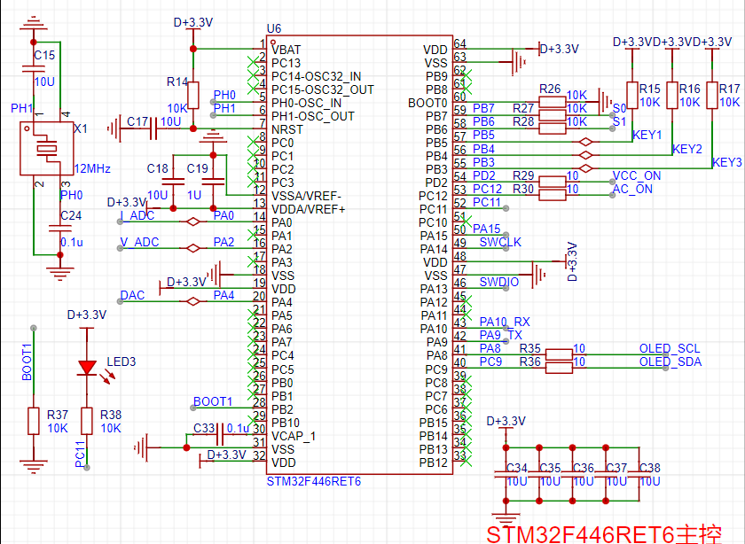
This design uses an STM32F446RET6 main controller.
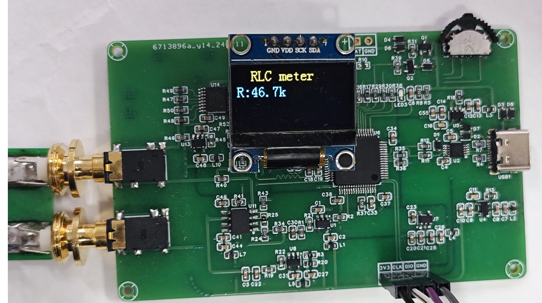
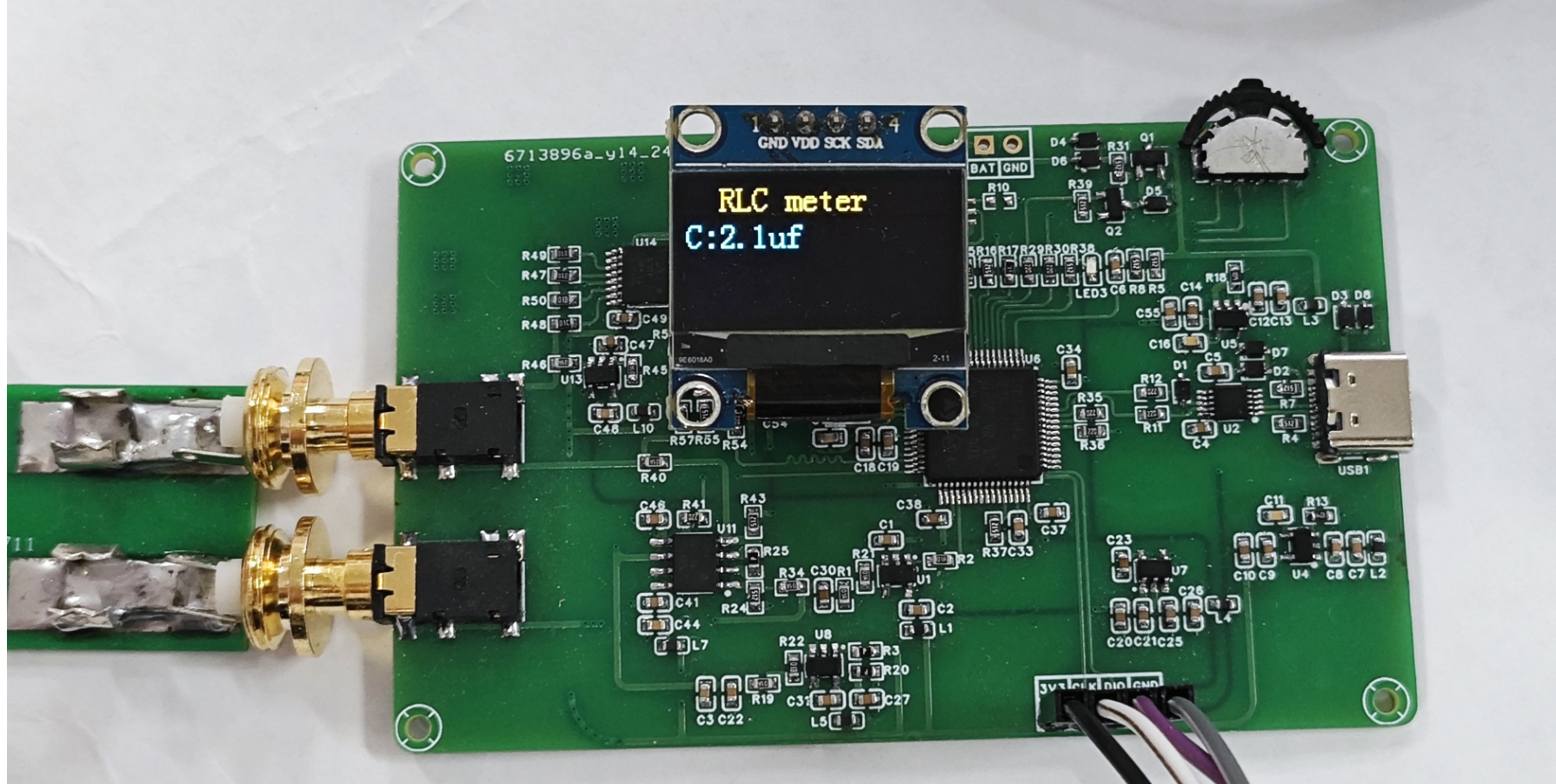
This design uses an OLED display; the top row displays the currently tested L, C, and R values.
This project has an automatic range switching function and a wide measurement range, which can meet general needs.
Note: Do not test high-voltage components that have not undergone proper discharge treatment, as this may easily damage the circuit.
原理解析(硬件说明)
此处可填写项目的设计原理,将设计的原理拆分解析,示例:
本项目由以下部分组成,主控部分、正负电源部分、充电电路部分、测试电路部分组成,本项目主要是通过主控发出DAC,再给到一级运放提供偏执电压,再经过二级运放,对采到的电流,电压信号进行采集,放大的处理,最后再将采集到的信号送到单片机的DAC,单片机进行计算,得出R,C,L的值。


1--主控电路:

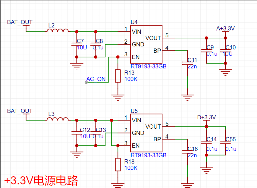
2--正负电源电路:

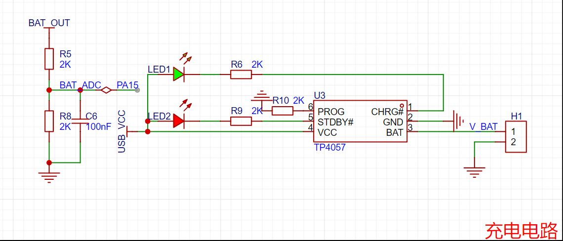
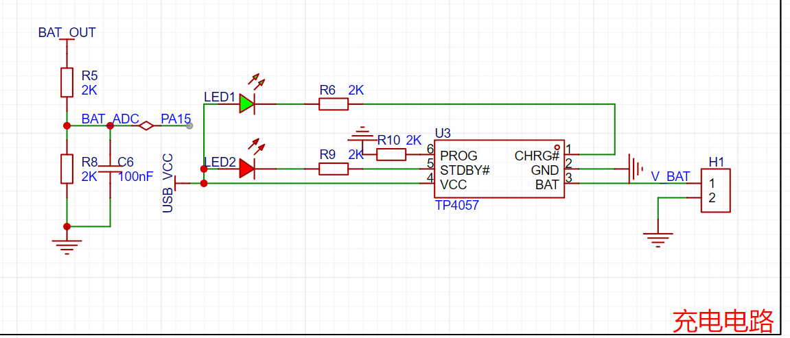
3--充电电路:
4--测试电路:


软件代码
// 测电阻自动换挡
void R_GEARS_APP(void)
{
uint8_t x, y, z;
float global_min_value = FLT_MAX;
float difference_value[4][4][4]; // VPP1-VPP2 差值的绝对值
struct ADC_DATA AUTO_ADC1_DATA[4][4]; // 自动换挡数据
struct ADC_DATA AUTO_ADC2_DATA[4][4]; // 自动换挡数据
struct GEARS_MIN gears_min[4]; // 每一挡位最小数值的数据
// 得到所有档位的值将所得到的值统计出来
for (x = 0; x < 4; x++) // 档位
{
for (y = 0; y < 4; y++) // 放大倍数档位
{
//
IR_gears_set(x); // Gear shift value for sampling resistor shifting
LCR_gears_set(y); // Amplification factor shifting
osDelay(10); // Wait for voltage stabilization after shifting gears
ADC_DATA_APP(); // Acquire VPP for each unit
// Save gear value
AUTO_ADC1_DATA[x][y].gears.gears_IR = x;
AUTO_ADC2_DATA[x][y].gears.gears_IR = x;
// Save sampling resistor value
AUTO_ADC1_DATA[x][y].gears.gears_IR_data = GREAS_DATA.gears.gears_IR_data;
AUTO_ADC2_DATA[x][y].gears.gears_IR_data = GREAS_DATA.gears.gears_IR_data;
// Save the magnification level value:
AUTO_ADC1_DATA[x][y].gears.gears_LCR = y;
AUTO_ADC2_DATA[x][y].gears.gears_LCR = y;
// Save the magnification value:
AUTO_ADC1_DATA[x][y].gears.gears_LCR_data = GREAS_DATA.gears.gears_LCR_data;
AUTO_ADC2_DATA[x][y].gears.gears_LCR_data = GREAS_DATA.gears.gears_LCR_data;
// Save the peak-to-peak value
: AUTO_ADC1_DATA[x][y].ADC_VPP = ADC1_DATA.ADC_VPP;
AUTO_ADC2_DATA[x][y].ADC_VPP = ADC2_DATA.ADC_VPP;
}
}
// Find the minimum difference in VPP at each level:
for (x = 0; x < 4; x++)
{
gears_min[x].Value_MIN = FLT_MAX;
for (y = 0; y < 4; y++)
{
for (z = 0; z < 4; z++)
{
difference_value[x][y][z] = fabs(AUTO_ADC1_DATA[x][y].ADC_VPP - AUTO_ADC2_DATA[x][z].ADC_VPP); // Get the absolute value of the VPP difference floating-point number
if (difference_value[x][y][z] < gears_min[x].Value_MIN) // Minimum value under all combinations of X and Y
{
gears_min[x].Value_MIN = difference_value[x][y][z];
// Record the minimum amplification level
gears_min[x].ADC1Index_MIN = y;
gears_min[x].ADC2Index_MIN = z;
// Record the sampling resistor value of the minimum group
gears_min[x].ADC1gears_IR = AUTO_ADC1_DATA[x][y].gears.ge
void ADC_DATA_APP(void)
{
// Convert voltage values
for (int i = 0; i < ADC_LEN; i++)
{
ADC1_V[i] = ADC1_BUUF[i] * 3.3f / 4096.0f;
ADC2_V[i] = ADC2_BUUF[i] * 3.3f / 4096.0f;
}
// Perform low-pass filtering on the ADC voltage data, with a cutoff frequency of 1kHz
arm_fir_f32_ADC1();
arm_fir_f32_ADC2();
// When performing low-pass filtering, the initial waveform has boundary effects, and the calculated minimum value is incorrect.
// The method to eliminate boundary effects here is not to start the calculation from the very beginning, but to shift the calculated data backward and skip the incorrect data.
// Boundary effects affect the first x samples. The specific number of samples can be checked by referring to the waveform. Just skip the boundary effect region.
const uint32_t ADC1_boundary_effect_samples = 200;
const uint32_t ADC2_boundary_effect_samples = 200;
// 调整数组指针和长度跳过边界效应区域
float32_t *start_ADC1_ptr = ADC1_V_Output + ADC1_boundary_effect_samples;
float32_t *start_ADC2_ptr = ADC2_V_Output + ADC2_boundary_effect_samples;
uint32_t ADC1_adjusted_len = ADC_LEN - ADC1_boundary_effect_samples;
uint32_t ADC2_adjusted_len = ADC_LEN - ADC2_boundary_effect_samples;
// 最小值
arm_min_f32(start_ADC1_ptr, ADC1_adjusted_len, &ADC1_DATA.ADC_MIN, &ADC1_DATA.Index_MIN);
arm_min_f32(start_ADC2_ptr, ADC2_adjusted_len, &ADC2_DATA.ADC_MIN, &ADC2_DATA.Index_MIN);
// Adjust the index to reflect the index of the original array
ADC1_DATA.Index_MIN += ADC1_boundary_effect_samples;
ADC2_DATA.Index_MIN += ADC2_boundary_effect_samples;
// Maximum value
arm_max_f32(ADC1_V_Output, ADC_LEN, &ADC1_DATA.ADC_MAX, &ADC1_DATA.Index_MAX);
arm_max_f32(ADC2_V_Output, ADC_LEN, &ADC2_DATA.ADC_MAX, &ADC2_DATA.Index_MAX);
// Peak value
ADC1_DATA.ADC_VPP = (ADC1_DATA.ADC_MAX) - (ADC1_DATA.ADC_MIN);
ADC2_DATA.ADC_VPP = (ADC2_DATA.ADC_MAX) - (ADC2_DATA.ADC_MIN);
}
// Low-pass filter coefficients 64th order filter Sampling frequency: 134635HZ Cutoff frequency: 1Khz Requires precision but cannot be too high The higher the filter order, the more accurate the filtering, but the slower the filtering speed
const float firCoeffs32LP[NUM_TAPS] =
{
0.001636382425, 0.001727766707, 0.001915873145, 0.002206306905, 0.002603286877,
0.003109541256, 0.003726221155, 0.004452842288, 0.005287249107, 0.006225605495,
0.007262411993, 0.008390551433, 0.00960135553, 0.01088470593, 0.01222915016,
0.01362204459, 0.01504972111, 0.01649766229, 0.01795070246, 0.01939323545,
0.02080943249, 0.0221834667, 0.02349973656, 0.02474309318, 0.02589905635,
0.02695403248, 0.02789550647, 0.02871222794, 0.02939438447, 0.02993373573,
0.03032374196, 0.03055966087, 0.03063862212, 0.03055966087, 0.03032374196,
0.02993373573, 0.02939438447, 0.02871222794, 0.02789550647, 0.02695403248,
0.02589905635, 0.02474309318, 0.02349973656, 0.0221834667, 0.02080943249,
0.01939323545, 0.01795070246, 0.01649766229, 0.01504972111, 0.01362204459,
0.01222915016, 0.01088470593, 0.00960135553, 0.008390551433, 0.007262411993,
0.006225605495, 0.005287249107, 0.004452842288, 0.003726221155, 0.003109541256,
0.002603286877, 0.002206306905, 0.001915873145, 0.001727766707, 0.001636382425};
/**********************************************************************************************************
* 函数名: arm_fir_f32_ADCx
* 功能说明: 调用函数arm_fir_f32_lp实现低通滤波器
* 形参:无
* 返回值: 无
**********************************************************************************************************/
static void arm_fir_f32_ADC1(void)
{
uint32_t i;
arm_fir_instance_f32 S;
float *inputF32, *outputF32;
// 初始化输入输出缓存指针
inputF32 = &ADC1_V[0];
outputF32 = &ADC1_V_Output[0];
// 初始化结构体S
arm_fir_init_f32(&S, NUM_TAPS, (float32_t *)&firCoeffs32LP[0], &firStateF32[0], blockSize);
// 实现FIR滤波,这里每次处理1个点
for (i = 0; i < numBlocks; i++)
{
arm_fir_f32(&S, inputF32 + (i * blockSize), outputF32 + (i * blockSize), blockSize);
} The complete assembly diagram can be placed here.
Figure 1: Resistance test diagram Figure 2: Capacitance test diagram Figure 3: Inductance test diagram


PDF_SmartRCLTable.zip
Altium_SmartRCLTable.zip
PADS_Smart RCL Table.zip
BOM_Smart RCL Table.xlsx
91998
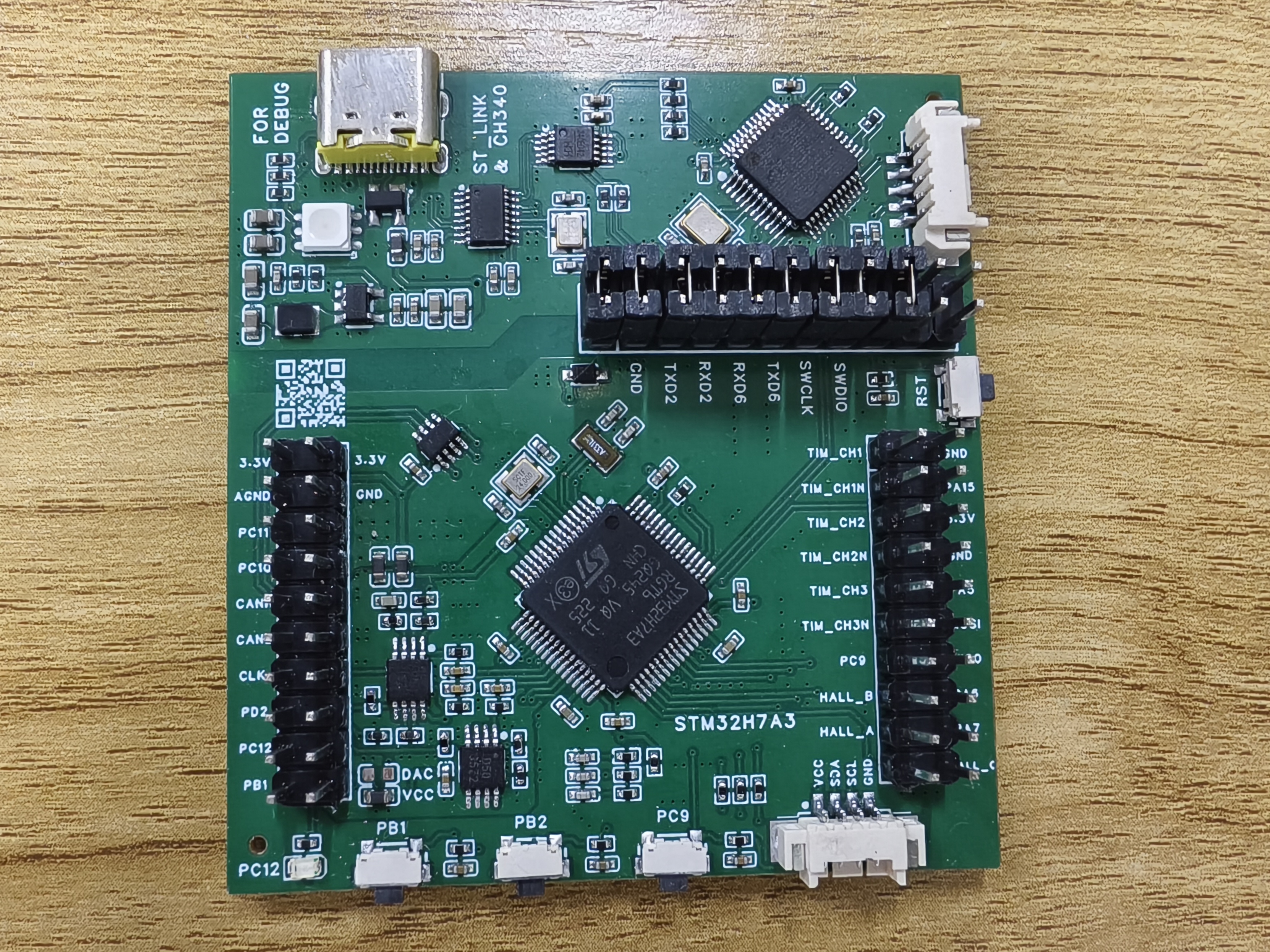
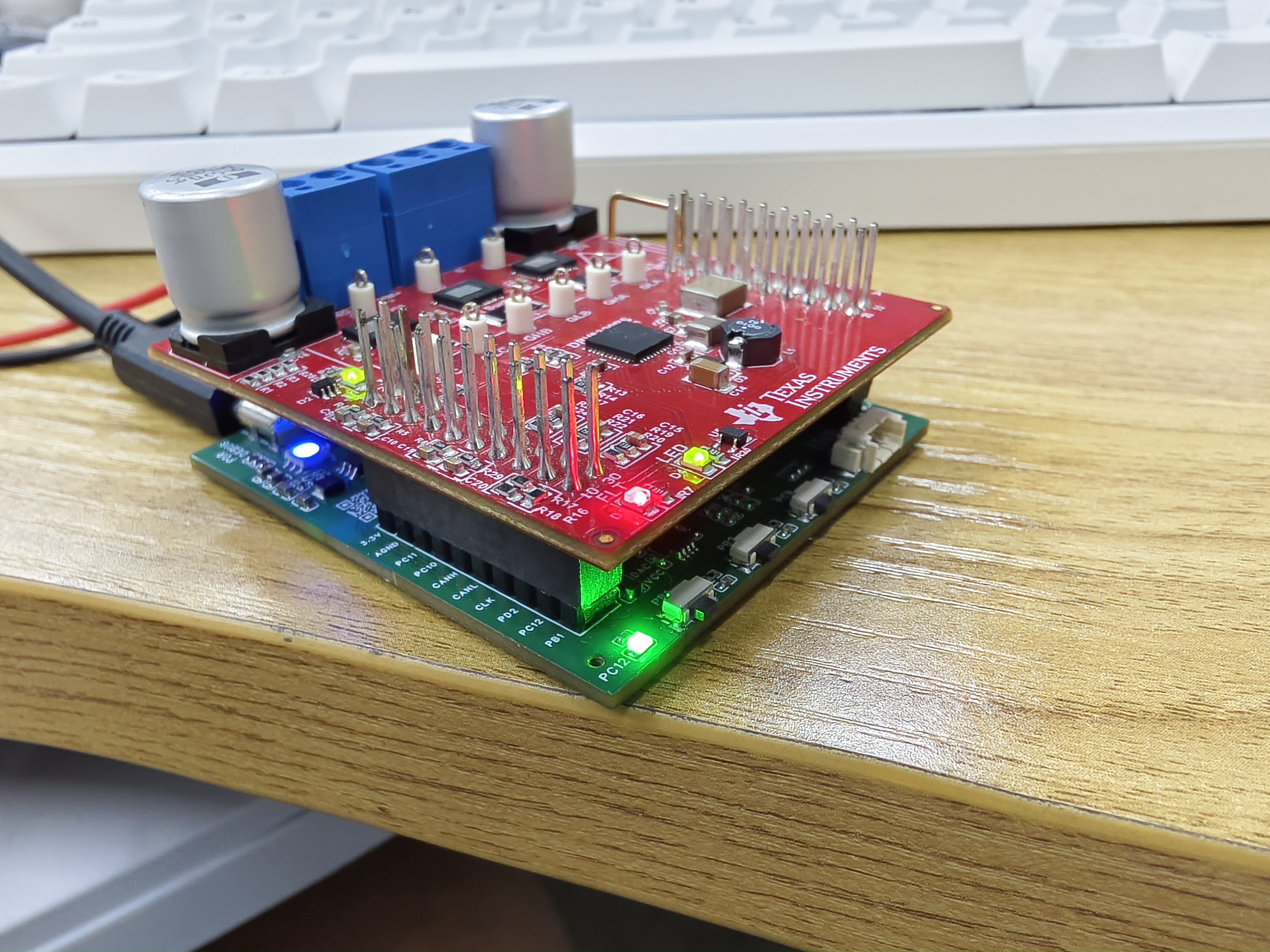
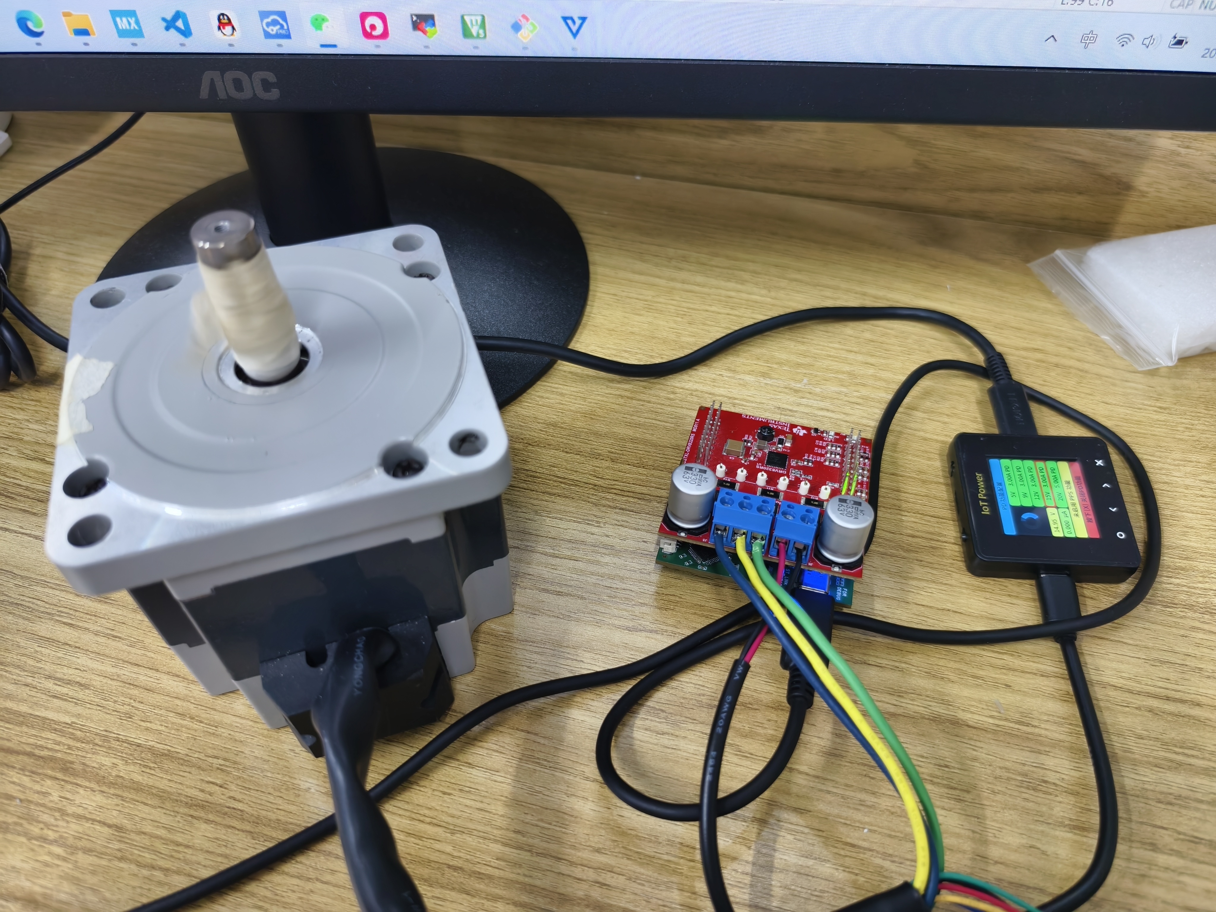
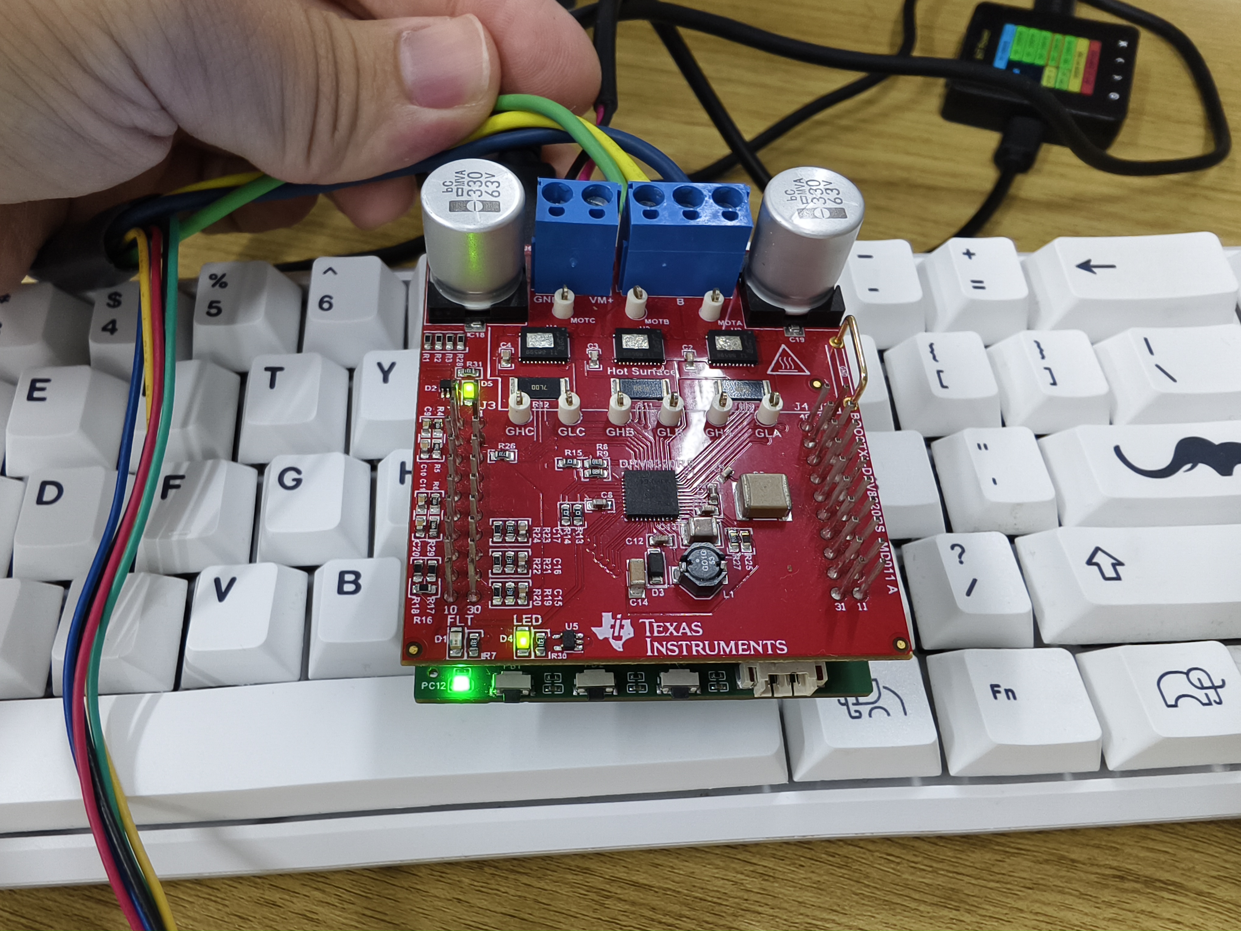
STM32H7A3-FOC Motor Development Board - LaunchPad
This development board was designed to be compatible with TI's BOOSTXL-DRV8320RS motor drive module, mimicking the appearance of TI's MSP430 series boards.
This development board, designed to be compatible with TI's BOOSTXL-DRV8320RS motor driver module, mimics the appearance of TI's MSP430 series boards.
The board uses the STM32H7A3RGT6 as the main control chip, with an ARM Cortex M7 core and a 280MHz clock speed. The M7 core is chosen for its double-precision floating-point operation and ability to execute two instructions per cycle, allowing for the execution of complex algorithms.
This design employs an all-in-one debugging method, requiring only a single USB Type-C interface for debugging. A USB hub chip expands the interface to provide three ports: one for the onboard CH340, one for the onboard ST-LINK, and one for the MCU's USB device. The onboard ST-LINK can switch firmware to JLINK-OB and also features a virtual serial port. The ST-LINK virtual serial port connects to UART6 for the RT-Thread console; the CH340 connects to UART2 for the VOFA+ host computer.
The operational amplifier circuit in the schematic is only half complete, forming a non-inverting proportional amplifier circuit with the upper-layer BOOSTXL-DRV8320RS board. Users can modify it according to their needs. Motor current and voltage sampling tests showed normal operation, and a non-inductive current loop can be closed.
ST-LINK circuit reference project: STLINK/JLINK_OB/DAPLINK - LCSC Open Source Hardware Platform (oshwhub.com)


PDF_STM32H7A3-FOC Motor Development Board-LaunchPad.zip
Altium_STM32H7A3-FOC Motor Development Board-LaunchPad.zip
PADS_STM32H7A3-FOC Motor Development Board-LaunchPad.zip
BOM_STM32H7A3-FOC Motor Development Board-LaunchPad.xlsx
91999
electronic


 京公网安备 11010802033920号

 LT-1534-120-250


