Preface:
I've always wanted to learn ESP32, and this time I finally had the chance. I used to develop on Keil, but this time I followed LCSC's tutorials. Although the learning journey was bumpy, I've finally gained something. Anyway, even though I was late, I never missed a day.
I built it all myself, which is very rewarding.
Functional Design and Implementation Status:
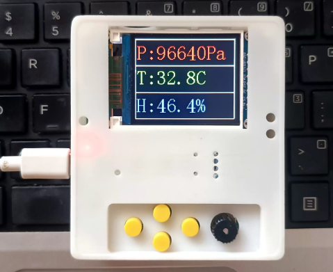
1- Supports monitoring indoor light, temperature, humidity, and pressure data acquisition (completed).
2- Supports wireless data transmission for convenient remote access; AP + Bluetooth functionality has been verified and is awaiting integration.
3- Supports image playback; image display has been verified and is awaiting integration.
4- Supports buzzer alerts (completed)
. 5- Supports desktop placement (completed).
6- Supports battery charging and discharging (completed)
. 7- Supports low battery alarm (completed).
Hardware Design
: The main controller
uses an ESP32-S3, a development board purchased directly from LCSC. This project was also to learn ESP32; its 240MHz clock speed and dual-core support were the main reasons I was interested.
The pinout circuit of this board is as follows:

Button design:
To accommodate future functionalities, as many buttons as possible have been reserved.

A rotary encoder interface has also been reserved.

All the above circuits have added debounce capacitors; don't skimp on this!
Indicator light design:
Two pull-up indicator lights are reserved, plus one more indicator light on the development board. A total of three usable indicator lights. Display

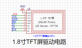
screen design:
I happened to have a 1.8-inch TFT display screen on hand, which I could utilize. I was learning how to drive a color SPI interface screen using an ESP32. This really stumped me. It was too difficult to adjust.
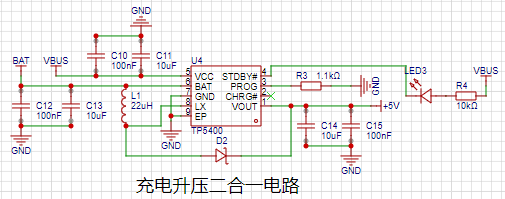
Charging and discharging circuit:
I purchased a TP5400 from LCSC; it's cheap and easy to use. I used this in almost all LCSC activities.
The circuit is simple, reliable, and practical. Just copy it directly.
Lithium battery power monitoring:
A fully charged lithium battery is around 4.2V, requiring voltage division for data acquisition. It cannot exceed 3.3V, determined by the ESP32's AD converter. As shown below:

Light intensity detection
: A photoresistor is used; the stronger the light, the lower the resistance. Based on this principle, a pull-up voltage divider is used. The ESP32's AD converter then acquires the data. As shown below:

The buzzer
circuit has various alarms. The circuit is simple, as shown below:

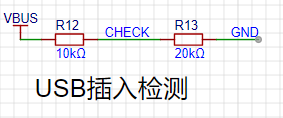
USB detection
can detect when the USB is plugged in for charging. Because the input is 5V, voltage division is performed to protect the interface.
As shown below: The temperature and humidity
sensor module
uses AHT21B to collect data, and the atmospheric pressure sensor uses BMP280.
Both use IIC interfaces, so the interfaces can share the IIC bus. As shown in the figure below:
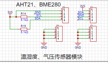
The tutorial does not include porting these two modules, as writing them yourself would be too painful. However, the lessons learned are also very rich.
The lithium battery interface
has a reserved 2.54mm pin header, which can be soldered or directly inserted.

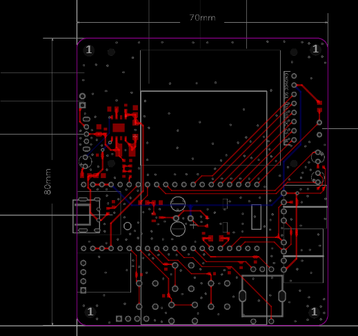
The PCB design
uses a 2-layer board, FR-4 board material, 1.2mm thick, and 70x80mm dimensions.
The casing design
uses LCSC EDA, and LCSC's 3D models are becoming increasingly realistic. The progress is really fast! Domestic EDA has a bright future.

The software design and development
follows the methods in the LCSC tutorial, and vscode and esp-idf are installed.
Here, I would like to remind everyone to use the version in the tutorial, otherwise, various problems will arise, and you will have to redo it.
Anyway, I went through all sorts of pain. Since this is a learning process, don't waste time on setting up the environment.
Later, I'll explain some areas where I spent a lot of time, especially where LCSC didn't provide direct examples. For
the screen driver,
I followed LCSC's tutorial, porting the framework from the 1.69-inch color screen to the 1.8-inch color screen.
First, the pin configuration:
#ifndef __LCD_INIT_H
#define __LCD_INIT_H
#include "driver/gpio.h"
#include "driver/spi_master.h"
#include "freertos/FreeRTOS.h"
#include "freertos/task.h"
#include "esp_rom_sys.h"
#define USE_HORIZONTAL 2 //Set landscape or portrait display 0 or 1 for portrait 2 or 3 for landscape
#if USE_HORIZONTAL==0||USE_HORIZONTAL==1
#define LCD_W 128
#define LCD_H 160
#else
#define LCD_W 160
#define LCD_H 128
#endif
#ifndef u8
#define u8 uint8_t
#endif
#ifndef u16
#define u16 uint16_t
#endif
#ifndef u32
#define u32 uint32_t
#endif
//-----------------LCD port porting----------------
#define LCD_SCL_PIN 7
#define LCD_MOSI_PIN 6
#define LCD_RES_PIN 5
#define LCD_DC_PIN 4
#define LCD_CS_PIN 3
#define LCD_BLK_PIN 2
//-----------------LCD port definition----------------
#define LCD_RES_Clr() gpio_set_level(LCD_RES_PIN,0)//RES
#define LCD_RES_Set() gpio_set_level(LCD_RES_PIN,1)
#define LCD_DC_Clr() gpio_set_level(LCD_DC_PIN,0)//DC
#define LCD_DC_Set() gpio_set_level(LCD_DC_PIN,1)
#define LCD_BLK_Clr() gpio_set_level(LCD_BLK_PIN,0)//BLK
#define LCD_BLK_Set() gpio_set_level(LCD_BLK_PIN,1)
void delay_us(int us);
void delay_ms(int ms);
void LCD_GPIO_Init(void);//Initialize GPIO
void LCD_Writ_Bus(u8 dat);//Simulate SPI timing
void LCD_WR_DATA8(u8 dat);//Write one byte
void LCD_WR_DATA(u16 dat);//Write two bytes
void LCD_WR_REG(u8 dat); // Write an instruction
void LCD_Address_Set(u16 x1,u16 y1,u16 x2,u16 y2); // Set coordinate function
void LCD_Init(void); // LCD initialization
#endif
Next is pin initialization
void LCD_GPIO_Init(void)
{
esp_err_t ret;
spi_bus_config_t buscfg={
.miso_io_num=NULL,
.mosi_io_num=LCD_MOSI_PIN,
.sclk_io_num=LCD_SCL_PIN,
.quadwp_io_num=-1,
.quadhd_io_num=-1,
.max_transfer_sz= 160 *128*3+8 // Maximum transfer size
};
spi_device_interface_config_t devcfg={
.clock_speed_hz=80*1000*1000, //Clock out at 80 MHz
.mode=3, //SPI mode 3
.spics_io_num=LCD_CS_PIN, //CS pin
.queue_size=7, //Transaction queue size of 7
.pre_cb=lcd_spi_pre_transfer_callback, // Callback before data transfer, used for D/C (data command) lines to handle separately
};
// Initialize SPI bus
ret=spi_bus_initialize(SPI2_HOST, &buscfg, SPI_DMA_CH_AUTO);
ESP_ERROR_CHECK(ret);
// Add SPI bus driver
ret=spi_bus_add_device(SPI2_HOST, &devcfg, &spi_port);
ESP_ERROR_CHECK(ret);
gpio_reset_pin(LCD_RES_PIN); // Initialize pin
gpio_set_direction(LCD_RES_PIN, GPIO_MODE_DEF_OUTPUT); // Configure pin to output mode
gpio_reset_pin(LCD_DC_PIN); // Initialize pin
gpio_set_direction(LCD_DC_PIN, GPIO_MODE_DEF_OUTPUT); // Configure pin to output mode
gpio_reset_pin(LCD_BLK_PIN); // Initialize pin
gpio_set_direction(LCD_BLK_PIN, GPIO_MODE_DEF_OUTPUT); // Configure pin to output mode
}
Finally, the screen initialization parameters
void LCD_Init(void)
{
LCD_GPIO_Init(); // Initialize GPIO
LCD_RES_Clr(); // Reset
delay_ms(100);
LCD_RES_Set();
delay_ms(100);
LCD_BLK_Set(); // Turn on backlight
delay_ms(100);
//************* Start Initial Sequence **********//
LCD_WR_REG(0x11); //Sleep out
delay_ms(120); // Delay 120ms
//------------------------------------ST7735S Frame Rate-----------------------------------------//
LCD_WR_REG(0xB1);
LCD_WR_DATA8(0x05);
LCD_WR_DATA8(0x3C);
LCD_WR_DATA8(0x3C);
LCD_WR_REG(0xB2);
LCD_WR_DATA8(0x05);
LCD_WR_DATA8(0x3C);
LCD_WR_DATA8(0x3C);
LCD_WR_REG(0xB3);
LCD_WR_DATA8(0x05);
LCD_WR_DATA8(0x3C);
LCD_WR_DATA8(0x3C);
LCD_WR_DATA8(0x05);
LCD_WR_DATA8(0x3C);
LCD_WR_DATA8(0x3C);
//------------------------------------End ST7735S Frame Rate---------------------------------//
LCD_WR_REG(0xB4); //Dot inversion
LCD_WR_DATA8(0x03);
//------------------------------------ST7735S Power Sequence---------------------------------//
LCD_WR_REG(0xC0);
LCD_WR_DATA8(0x28);
LCD_WR_DATA8(0x08);
LCD_WR_DATA8(0x04);
LCD_WR_REG(0xC1);
LCD_WR_DATA8(0XC0);
LCD_WR_REG(0xC2);
LCD_WR_DATA8(0x0D);
LCD_WR_DATA8(0x00);
LCD_WR_REG(0xC3);
LCD_WR_DATA8(0x8D);
LCD_WR_DATA8(0x2A);
LCD_WR_REG(0xC4);
LCD_WR_DATA8(0x8D);
LCD_WR_DATA8(0xEE);
//---------------------------------End ST7735S Power Sequence-------------------------------------//
LCD_WR_REG(0xC5); //VCOM
LCD_WR_DATA8(0x1A);
LCD_WR_REG(0x36); //MX, MY, RGB mode
if(USE_HORIZONTAL==0){
LCD_WR_DATA8(0x00);
}
else if(USE_HORIZONTAL==1){
LCD_WR_DATA8(0xC0);
}
else if(USE_HORIZONTAL==2){
LCD_WR_DATA8(0x70);
}
else {
LCD_WR_DATA8(0xA0);
}
//------------------------------------ST7735S Gamma Sequence---------------------------------//
LCD_WR_REG(0xE0);
LCD_WR_DATA8(0x04);
LCD_WR_DATA8(0x22);
LCD_WR_DATA8(0x07);
LCD_WR_DATA8(0x0A);
LCD_WR_DATA8(0x2E);
LCD_WR_DATA8(0x30);
LCD_WR_DATA8(0x25);
LCD_WR_DATA8(0x2A);
LCD_WR_DATA8(0x28);
LCD_WR_DATA8(0x26);
LCD_WR_DATA8(0x2E);
LCD_WR_DATA8(0x3A);
LCD_WR_DATA8(0x00);
LCD_WR_DATA8(0x01);
LCD_WR_DATA8(0x03);
LCD_WR_DATA8(0x13);
LCD_WR_REG(0xE1);
LCD_WR_DATA8(0x04);
LCD_WR_DATA8(0x16);
LCD_WR_DATA8(0x06);
LCD_WR_DATA8(0x0D);
LCD_WR_DATA8(0x2D);
LCD_WR_DATA8(0x26);
LCD_WR_DATA8(0x23);
LCD_WR_DATA8(0x27);
LCD_WR_DATA8(0x27);
LCD_WR_DATA8(0x25);
LCD_WR_DATA8(0x2D
);
LCD_WR_DATA8
(0x3B);
LCD_WR_DATA8(0x00);
LCD_WR_DATA8(0x01)
;
LCD_WR_REG(0x3A); //65k mode
LCD_WR_DATA8(0x05);
LCD_WR_REG(0x29); //Display on
}
Please note the above, as errors will cause various problems.
AHT21B driver
header file
#ifndef _BSP_AHT20_H_
#define _BSP_AHT20_H_
#include "freertos/FreeRTOS.h"
#include "freertos/task.h"
#include "esp_log.h"
#include "freertos/queue.h"
#include
#include "sdkconfig.h"
#include "driver/gpio.h"
#include "esp_log.h"
#include "rom/ets_sys.h"
#include "esp_system.h"
#include "driver/gpio.h"
#include "hardware/lcd_init.h"
//Port porting
#define AHT10_SCL_PIN 42
#define AHT10_SDA_PIN 41
//Set SDA output mode
#define SDA_OUT() `gpio_set_direction(AHT10_SDA_PIN,GPIO_MODE_OUTPUT)
` // Sets the SDA input mode.
`#define SDA_IN()` `gpio_set_direction(AHT10_SDA_PIN,GPIO_MODE_INPUT)
` // Gets the SDA pin level changes.
`#define SDA_GET()` `gpio_get_level(AHT10_SDA_PIN)
` // SDA and SCL outputs.
`#define SDA(x)` `gpio_set_level(AHT10_SDA_PIN, (x?1:0))` `
#define SCL(x)` `gpio_set_level(AHT10_SCL_PIN, (x?1:0))
` // `void delay_us(unsigned int us);` // `
void delay_ms(unsigned int ms);` `
void AHT21_GPIO_Init(void);` `
float Get_Temperature(void);
` `float Get_Humidity(void);`
`char` The functions are defined as follows: `aht21_read_data(void);
void IIC_Start(void);
void IIC_Stop(void);
void IIC_Send_Ack(unsigned char ack);
unsigned char I2C_WaitAck(void)
; void Send_Byte(uint8_t dat);
unsigned char Read_Byte(void);
#endif` . Each function was debugged step-by-step and can be used with confidence. `#include "hardware/bsp_aht20.h"` `#include "stdio.h"`h"float Temperature = 0;float Humidity = 0;// void delay_ms(unsigned int ms)// {// vTaskDelay(ms / portTICK_PERIOD_MS);// }// void delay_us(unsigned int us)// {// ets_delay_us(us);// }void AHT21_GPIO_Init(void)
{
gpio_config_t lll_config = {
.pin_bit_mask = (1ULL << AHT10_SCL_PIN) | (1ULL << AHT10_SDA_PIN), // Configure pin.mode
= GPIO_MODE_OUTPUT, // Output mode.pull_up_en
= GPIO_PULLUP_ENABLE, // Enable pull-up.pull_down_en
= GPIO_PULLDOWN_DISABLE, // Disable pull-
down.intr_type = GPIO_INTR_DISABLE // Disable pin interrupt
};
gpio_config(&lll_config);
}
void IIC_Start(void)
{
SDA_OUT();
SDA(1);
delay_us(5);
SCL(1);
delay_us(5);
SDA(0);
delay_us(5);
SCL(0);
delay_us(5);
}
void IIC_Stop(void)
{
SDA_OUT();
SCL(0);
SDA(0);
SCL(1);
delay_us(5);
SDA(1) ; delay_us (5 )
;
}
void IIC_Send_Ack(unsigned char ack ) {
SDA_OUT ( ) ; delay_us(5); SCL(0); SDA(1); } unsigned char I2C_WaitAck(void) { char ack = 0; unsigned char ack_flag = 10; SCL(0); SDA(1); SDA_IN(); delay_us(5); SCL(1); delay_us(5); while ((SDA_GET() == 1) && (ack_flag)) { ack_flag--; delay_us(5); } if (ack_flag <= 0) { IIC_Stop(); return 1; } else { SCL(0); SDA_OUT(); } return ack; } void Send_Byte(uint8_t dat) { int i = 0; SDA_OUT(); SCL(0); // Pull the clock low to start data transmission for (i = 0; i < 8; i++) { SDA((dat & 0x80) >> 7); delay_us(1); SCL(1); delay_us(5); SCL(0);
delay_us(5);
dat <<= 1;
}
}
unsigned char Read_Byte(void)
{
unsigned char i, receive = 0;
SDA_IN(); // SDA is set to input
for (i = 0; i < 8; i++)
{
SCL(0);
delay_us(5);
SCL(1);
delay_us(5);
receive <<= 1;
if (SDA_GET())
{
receive |= 1;
}
delay_us(5);
}
SCL(0);
return receive;
}
// Read the status register
uint8_t aht21_read_status(void)
{
uint8_t status_register_address = 0x71;
uint8_t status_byte;
IIC_Start();
Send_Byte(status_register_address);
if (I2C_WaitAck() == 1)
printf("warning -1
");
status_byte = Read_Byte();
IIC_Send_Ack(0);
IIC_Stop();
return status_byte;
}
// Send the acquisition command to AHT21
uint8_t aht21_send_gather_command(void)
{
uint8_t device_addr = 0x70;//Device address
uint8_t gather_command = 0xac;//Acquisition command
uint8_t gather_command_parameter_1 = 0x33;//Acquisition parameter 1
uint8_t gather_command_parameter_2 = 0x00;//Acquisition parameter 2
IIC_Start();
Send_Byte(device_addr);//Send device address
if( I2C_WaitAck() == 1 ) return 1;
Send_Byte(gather_command);//Send acquisition command
if( I2C_WaitAck() == 1 ) return 2;
Send_Byte(gather_command_parameter_1);//Send acquisition parameter 1
if( I2C_WaitAck() == 1 ) return 3;
Send_Byte(gather_command_parameter_2);//Send acquisition parameter 2
if( I2C_WaitAck() == 1 ) return 4;
IIC_Stop();
return 0;
}
//Initialize AHT21 via command byte
void aht21_device_init(void)
{
uint8_t device_addr = 0x70;//Device address
uint8_t init_command = 0xBE;//Initialization command
uint8_t init_command_parameter_1 = 0x08;//Acquisition parameter 1
uint8_t init_command_parameter_2 = 0x00;//Acquisition parameter 2
IIC_Start();
Send_Byte(device_addr);//Send device address
if( `I2C_WaitAck() == 1) printf("warning -5
");
Send_Byte(init_command); // Send initialization command
if (I2C_WaitAck() == 1) printf("warning -6
");
Send_Byte(init_command_parameter_1); // Send initialization parameter 1
if (I2C_WaitAck() == 1) printf("warning -7
");`
Send_Byte(init_command_parameter_2);//Send initialization parameter 2
if( I2C_WaitAck() == 1 ) printf("warning -8
");
IIC_Stop();
}
/**********************************************************************
* Function name: aht21_read_data
* Function description: Read temperature and humidity
* Function parameters: None
* Function return: 1: Uncalibrated 2: Read timeout 0: Read successful
* Author: LC
* Remarks: None
******************************************************************/
char aht21_read_data(void)
{
uint8_t data[6] = {0};
uint32_t temp = 0;
uint8_t aht21_status_byte = 0;
uint8_t timeout = 0;
//Read the status of AHT21
aht21_status_byte = aht21_read_status();
// Returns 1 if not calibrated
if( (aht21_status_byte & (1<<3)) == 0 )
{
aht21_device_init();
delay_ms(50);
return 1;
}
// Send acquisition command
aht21_send_gather_command();
do
{
delay_ms(1);
timeout++;
// Read AHT21 status
aht21_status_byte = aht21_read_status();
}while( ( ( aht21_status_byte & (1<<7) ) != 0 ) && ( timeout >= 80 ) );
// Returns 2 if read times out
if( timeout >= 80 ) return 2;
IIC_Start();
Send_Byte(0x71);
if( I2C_WaitAck() == 1 ) printf("error -1
");
Read_Byte(); // Read status, no need to save
IIC_Send_Ack(0);
// Read 6 bits of data
data[0] = Read_Byte();
IIC_Send_Ack(0);
data[1] = Read_Byte();
IIC_Send_Ack(0);
data[2] = Read_Byte();
IIC_Send_Ack(0);
data[3] = Read_Byte();
IIC_Send_Ack(0);
data[4] = Read_Byte();
IIC_Send_Ack(0);
data[5] = Read_Byte();
IIC_Send_Ack(0);
IIC_Stop();
// Integrate humidity data
temp = (data[0]<<12) | (data[1]<<4);
temp = temp | (data[2]>>4);
// Convert humidity data
// 2 to the power of 20 = 1048576
Humidity = temp / 1048576.0 * 100.0;
//Integrate humidity data
temp = ( (data[2]&0x0f)<< 16 ) | (data[3]<<8);
temp = temp | data[4];
//Convert humidity data
//2 to the power of 20 = 1048576
Temperature = temp / 1048576.0 * 200.0 - 50;
return 0;
}
/**************************************************************
* Function name: Get_Temperature
* Function function: Get the collected temperature data
* Input parameters: None
* Function return: Temperature data, unit ℃
* Author: LC
* Remarks: Data must be collected first, otherwise 0 or the previous data will be returned.
**********************************************************/
float Get_Temperature(void)
{
return Temperature;
}
/**********************************************************
* Function Name: Get_Humidity
* Function Function: Retrieves collected humidity data
* Input Parameters: None
* Function Return: Humidity data, unit %RH
* Author: LC
* Note: Data must be collected first, otherwise it returns 0 or the previous value
**********************************************************/
float Get_Humidity(void)
{
return Humidity;
}
The BMP280 driver
header file is as follows:
#ifndef __BMP280_H__
#define __BMP280_H__
/*********************************************************************************/
#include "hardware/bsp_aht20.h"
/*==============================================================================
REGISTERS
--------------------------------------------------------------------------------*/
#define BMP280_REGISTER_DIG_T1 0x88
#define BMP280_REGISTER_DIG_T2 0x8A
#define BMP280_REGISTER_DIG_T3 0x8C
#define BMP280_REGISTER_DIG_P1 0x8E
#define BMP280_REGISTER_DIG_P2 0x90
#define BMP280_REGISTER_DIG_P3 0x92
#define BMP280_REGISTER_DIG_P4 0x94
#define BMP280_REGISTER_DIG_P5 0x96
#define BMP280_REGISTER_DIG_P6 0x98
#define BMP280_REGISTER_DIG_P7 0x9A
#define BMP280_REGISTER_DIG_P8 0x9C
#define BMP280_REGISTER_DIG_P9 0x9E
#define BMP280_REGISTER_CHIPID 0xD0
#define BMP280_REGISTER_VERSION 0xD1
#define BMP280_REGISTER_SOFTRESET 0xE0
#define BMP280_REGISTER_CAL26 0xE1 // R calibration stored in 0xE1-0xF0
#define BMP280_REGISTER_CONTROL 0xF4
#define BMP280_REGISTER_CONFIG 0xF5
#define BMP280_REGISTER_PRESSUREDATA 0xF7
#define BMP280_REGISTER_TEMPDATA 0xFA
/*================================================================================*/
/*============================================================================
CALIBRATION DATA
--------------------------------------------------------------------------------*/
typedef struct
{
uint16_t dig_T1;
int16_t dig_T2;
int16_t dig_T3;
uint16_t dig_P1;
int16_t dig_P2;
int16_t dig_P3;
int16_t dig_P4;
int16_t dig_P5;
int16_t dig_P6;
int16_t dig_P7;
int16_t dig_P8;
int16_t dig_P9;
uint8_t dig_H1;
int16_t dig_H2;
uint8_t dig_H3;
int16_t dig_H4;
int16_t dig_H5;
int8_t dig_H6;
} bmp280_calib_data;
/*=========================================================================*/
uint8_t begin(void);
float readTemperature(void);
float readPressure(void);
#endif
函数实现如下
#include "BMP280.h"
void readCoefficients(void);
void write8(uint8_t reg, uint8_t value);
uint8_t read8(uint8_t reg);
uint16_t read16(uint8_t reg);
int16_t readS16(uint8_t reg);
uint16_t read16_LE(uint8_t reg); // little endian
int16_t readS16_LE(uint8_t reg); // little endian
//int8_t cs = -1;
uint8_t i2caddr = 0xEC;
// int32_t sensorID;
int32_t t_fine;
bmp280_calib_data bmp280_calib;
uint8_t begin(void)
{
if (read8(BMP280_REGISTER_CHIPID) != 0x58)
return 0;
readCoefficients();
write8(BMP280_REGISTER_CONTROL, 0x3F);
return 1;
}
/**************************************************************************/
/*!
@brief Writes an 8 bit value over I2C/SPI
*/
/**************************************************************************/
void write8(uint8_t reg, uint8_t value)
{
IIC_Start();
Send_Byte(i2caddr);
if (I2C_WaitAck())
printf("ADDR ACK ERORR
");
Send_Byte(reg);
if (I2C_WaitAck())
printf("REG ACK ERORR
");
Send_Byte(value);
if (I2C_WaitAck())
printf("Value ERORR
");
IIC_Stop();
// release the SPI bus
}
/**************************************************************************/
/*!
@brief Reads an 8 bit value over I2C
*/
/**************************************************************************/
uint8_t read8(uint8_t reg)
{
uint8_t value = 0;
IIC_Start();
Send_Byte(i2caddr);
if (I2C_WaitAck())
printf("ADDR ACK ERORR
");
Send_Byte(reg);
if (I2C_WaitAck())
printf("REG ACK ERORR
");
IIC_Start();
Send_Byte(i2caddr + 1);
if (I2C_WaitAck())
printf("ADDR ACK ERORR
");
value = Read_Byte();
IIC_Send_Ack(1);
IIC_Stop();
return value;
}
/**************************************************************************/
/*!
@brief Reads a 16 bit value over I2C
*/
/**************************************************************************/
uint16_t read16(uint8_t reg)
{
uint16_t value=0;
IIC_Start();
Send_Byte(i2caddr);
I2C_WaitAck();
Send_Byte(reg);
I2C_WaitAck();
IIC_Start();
Send_Byte(i2caddr + 1);
I2C_WaitAck();
value = Read_Byte();
IIC_Send_Ack(0);
value = (value << 8) | Read_Byte();
IIC_Send_Ack(1);
IIC_Stop();
return value;
}
uint16_t read16_LE(uint8_t reg)
{
uint16_t temp = read16(reg);
return (temp >> 8) | (temp << 8);
}
/**************************************************************************/
/*!
@brief Reads a signed 16 bit value over I2C
*/
/**************************************************************************/
int16_t readS16(uint8_t reg)
{
return (int16_t)read16(reg);
}
int16_t readS16_LE(uint8_t reg)
{
return (int16_t)read16_LE(reg);
}
/**************************************************************************/
/*!
@brief Reads the factory-set coefficients
*/
/**************************************************************************/
void readCoefficients(void)
{
bmp280_calib.dig_T1 = read16_LE(BMP280_REGISTER_DIG_T1);
bmp280_calib.dig_T2 = readS16_LE(BMP280_REGISTER_DIG_T2);
bmp280_calib.dig_T3 = readS16_LE(BMP280_REGISTER_DIG_T3);
bmp280_calib.dig_P1 = read16_LE(BMP280_REGISTER_DIG_P1);
bmp280_calib.dig_P2 = readS16_LE(BMP280_REGISTER_DIG_P2);
bmp280_calib.dig_P3 = readS16_LE(BMP280_REGISTER_DIG_P3);
bmp280_calib.dig_P4 = readS16_LE(BMP280_REGISTER_DIG_P4);
bmp280_calib.dig_P5 = readS16_LE(BMP280_REGISTER_DIG_P5);
bmp280_calib.dig_P6 = readS16_LE(BMP280_REGISTER_DIG_P6);
bmp280_calib.dig_P7 = readS16_LE(BMP280_REGISTER_DIG_P7);
bmp280_calib.dig_P8 = readS16_LE(BMP280_REGISTER_DIG_P8);
bmp280_calib.dig_P9 = readS16_LE(BMP280_REGISTER_DIG_P9);
}
/**************************************************************************/
/*!
*/
/**************************************************************************/
float readTemperature(void)
{
int32_t var1, var2;
float T;
int32_t adc_T = read16(BMP280_REGISTER_TEMPDATA);
adc_T <<= 8;
adc_T |= read8(BMP280_REGISTER_TEMPDATA + 2);
adc_T >>= 4;
var1 = ((((adc_T >> 3) - ((int32_t)bmp280_calib.dig_T1 << 1))) *
((int32_t)bmp280_calib.dig_T2)) >>
11;
var2 = (((((adc_T >> 4) - ((int32_t)bmp280_calib.dig_T1)) *
((adc_T >> 4) - ((int32_t)bmp280_calib.dig_T1))) >>
12) *
((int32_t)bmp280_calib.dig_T3)) >>
14;
t_fine = var1 + var2;
T = (t_fine * 5 + 128) >> 8;
return T / 100;
}
/**************************************************************************/
/*!
*/
/**************************************************************************/
float readPressure(void)
{
int64_t var1, var2, p;
int32_t adc_P = read16(BMP280_REGISTER_PRESSUREDATA);
adc_P <<= 8;
adc_P |= read8(BMP280_REGISTER_PRESSUREDATA + 2);
adc_P >>= 4;
var1 = ((int64_t)t_fine) - 128000;
var2 = var1 * var1 * (int64_t)bmp280_calib.dig_P6;
var2 = var2 + ((var1 * (int64_t)bmp280_calib.dig_P5) << 17);
var2 = var2 + (((int64_t)bmp280_calib.dig_P4) << 35);
var1 = ((var1 * var1 * (int64_t)bmp280_calib.dig_P3) >> 8) +
((var1 * (int64_t)bmp280_calib.dig_P2) << 12);
var1 = (((((int64_t)1) << 47) + var1)) * ((int64_t)bmp280_calib.dig_P1) >> 33;
if (var1 == 0)
{
return 0; // avoid exception caused by division by zero
}
p = 1048576 - adc_P;
p = (((p << 31) - var2) * 3125) / var1;
var1 = (((int64_t)bmp280_calib.dig_P9) * (p >> 13) * (p >> 13)) >> 25;
var2 = (((int64_t)bmp280_calib.dig_P8) * p) >> 19;
p = ((p + var1 + var2) >> 8) + (((int64_t)bmp280_calib.dig_P7) << 4);
return (float)p / 256;
}
ADC驱动
这里就不贴代码了,跟着立创教程学习就行,那里肯定比我讲解的详细。
按键、LED驱动
这里也不贴代码了,跟着立创教程学习就行,那里肯定比我讲解的详细。
wifi、蓝牙驱动
立创教程非常丰富,肯定比我讲解的详细,我就不献丑了。如下教程:
https://wiki.lckfb.com/zh-hans/esp32s3r8n8/esp-idf-beginner/wifi.html
演示效果
具体见附件和B站链接哦:
https://www.bilibili.The video (com/video/BV1GFt8eYEos/?vd_source=24f1befd6441a33d7b240715cb07c7b5) Although this trip was rushed, forcing myself to persevere yielded truly many rewards.a journey of a thousand miles beginning with a single step. No matter how difficult, you must take action first.
summarizes


 京公网安备 11010802033920号

 5962D9568501VPC


