Supports SVOOC, high voltage SCP (40W), UFCS (105W) protocols, etc.
Program code is included (see attachment). Some program notes are in the readme.md file.
Parameters:
Dimensions: Length * Width * Height = 105 * 71 * 28mm (excluding included cable)
; Weight: 366.3 g;
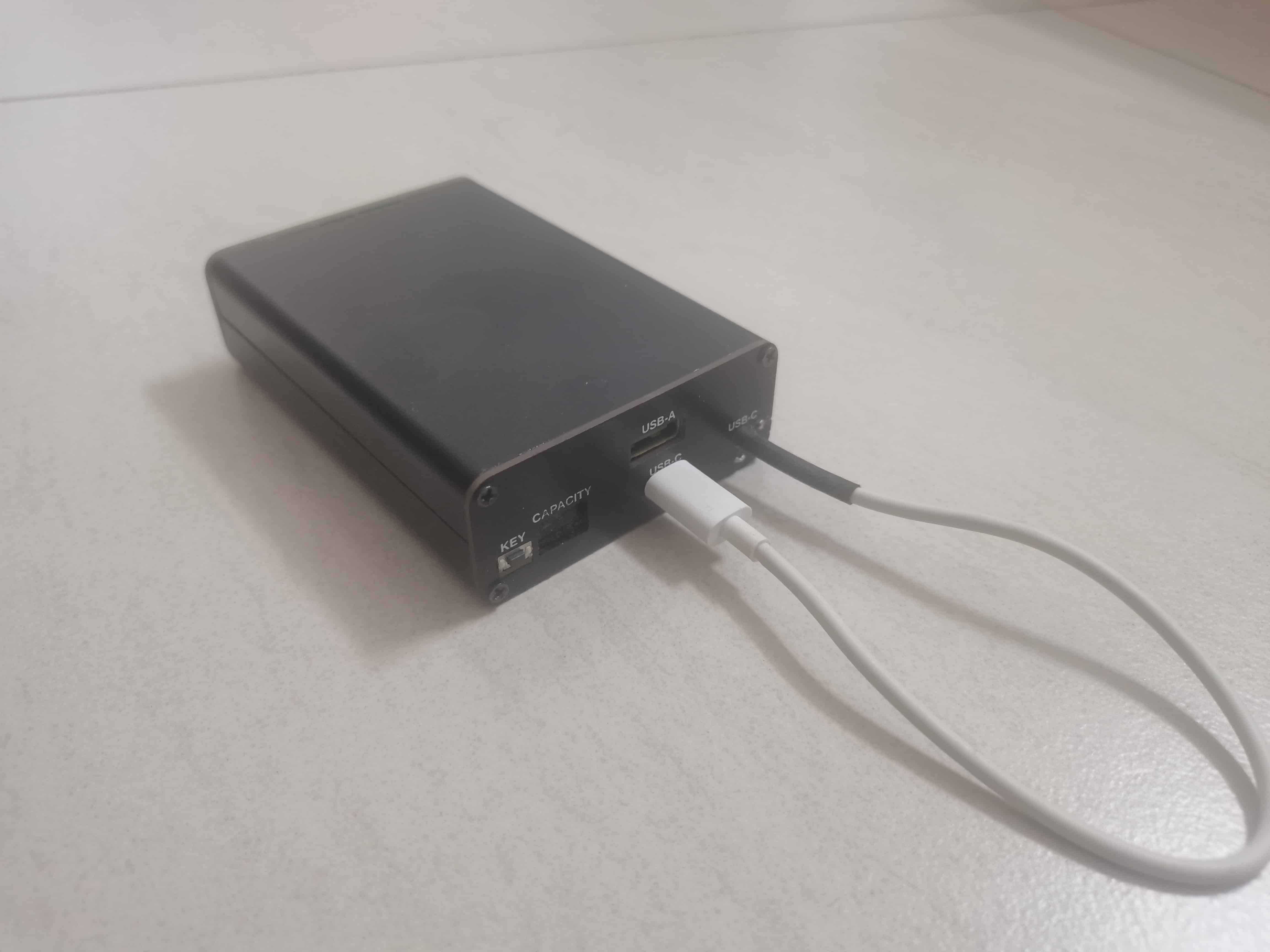
Display: 0.25-inch 188-digit digital tube with percentage and fast charging indicator;
Interfaces: USB-C * 2, USB * A;
Input Power: 60W max, 20V max, 3A max;
Output Power: 90W max, 20V max, 5A max;
LED Power: 1~18W;
Input Supported Protocols: PD3.0 / FCP / SCP / AFC / DCP / VOOC / UFCS, etc.;
Output Supported Protocols: PD3.0 / QC2.0~QC5 / FCP / SCP / AFC / PE / DCP / SVOOC / UFCS, etc.;
Testing:
Instrument:
Oscilloscope: SIGLENT/鼎阳SDS1102X-C
Multimeter: ZOYI/众仪 ZT219
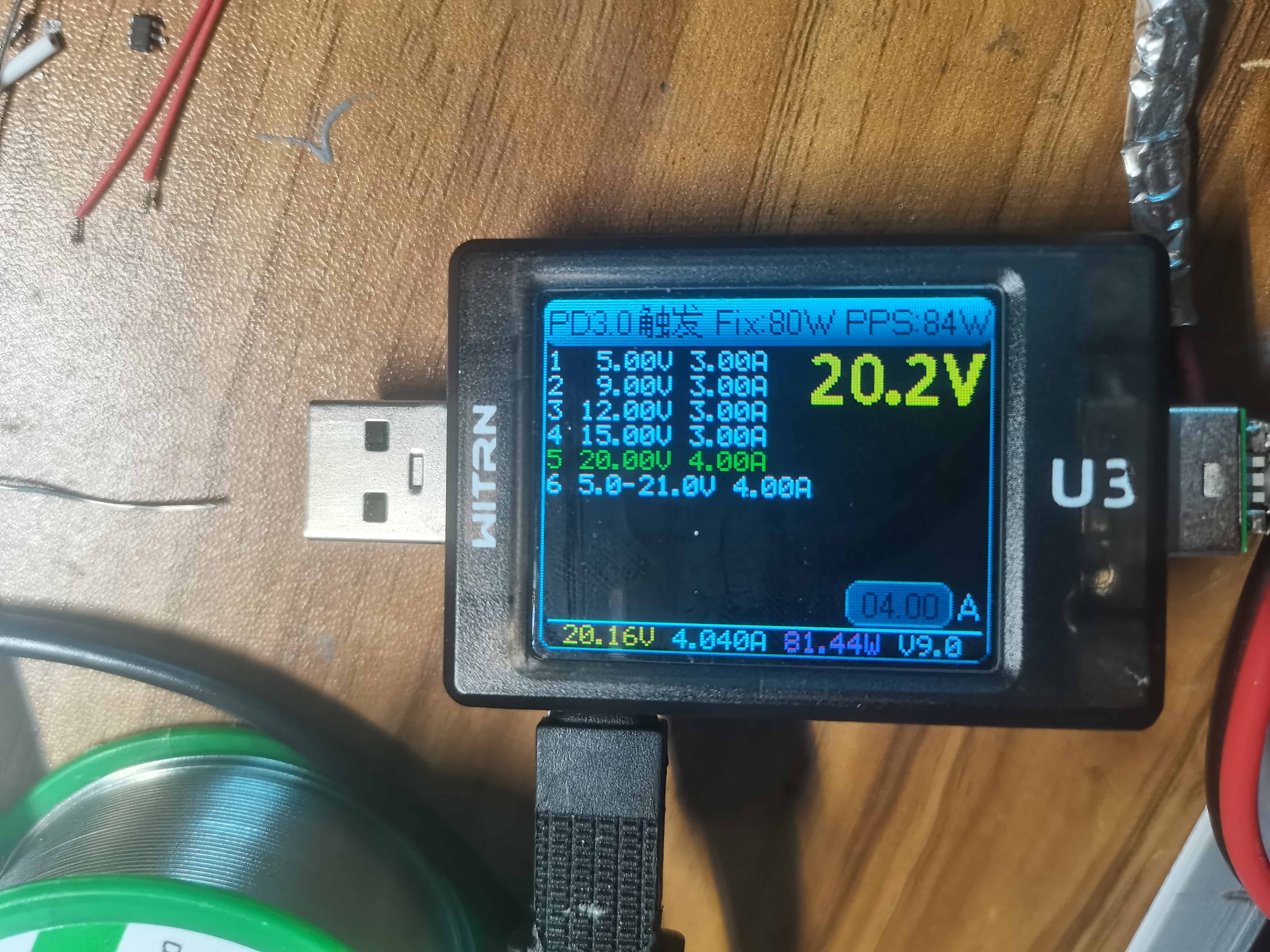
USB Multimeter: WITRN/维简 U3
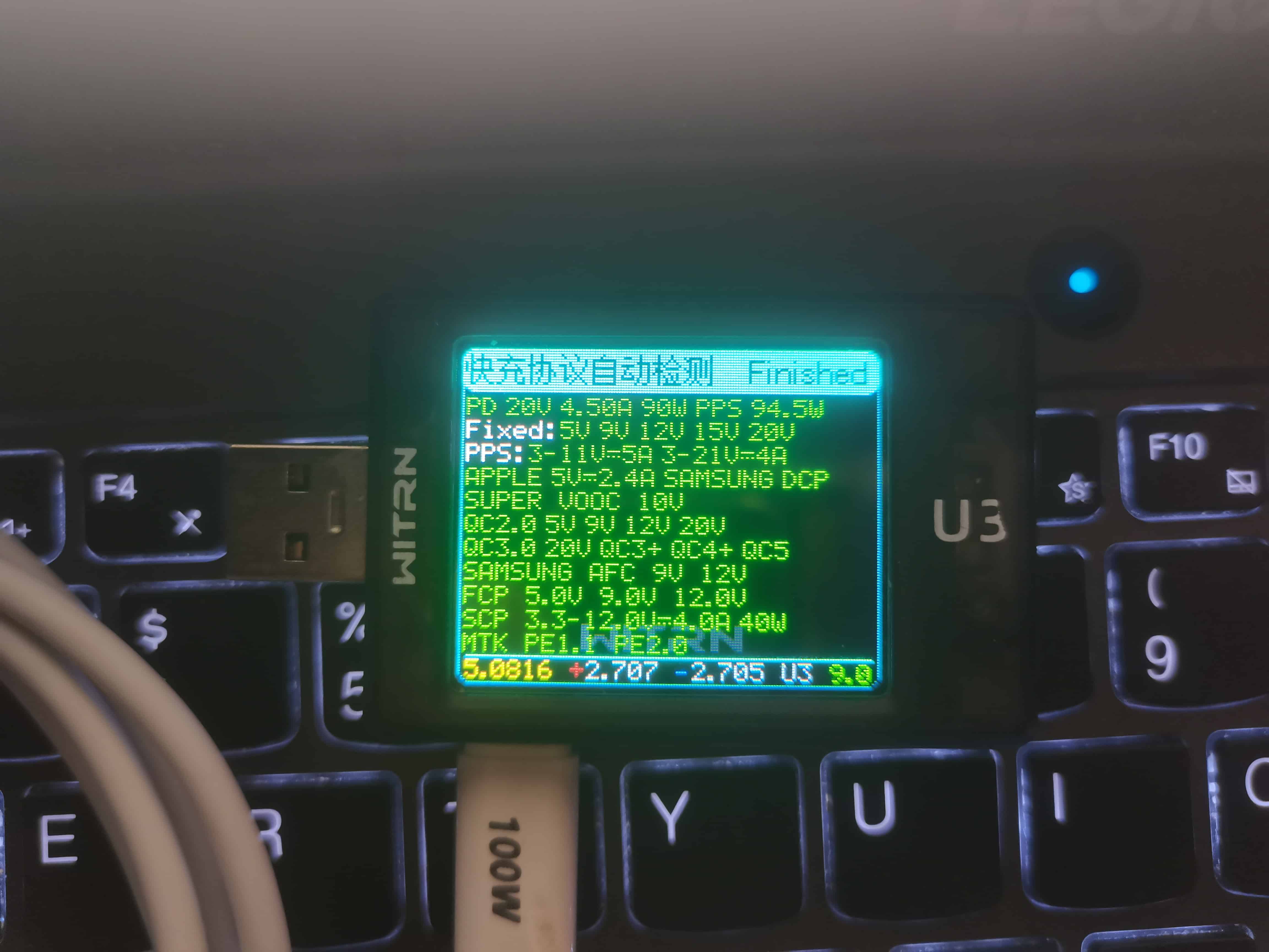
Protocol Test:
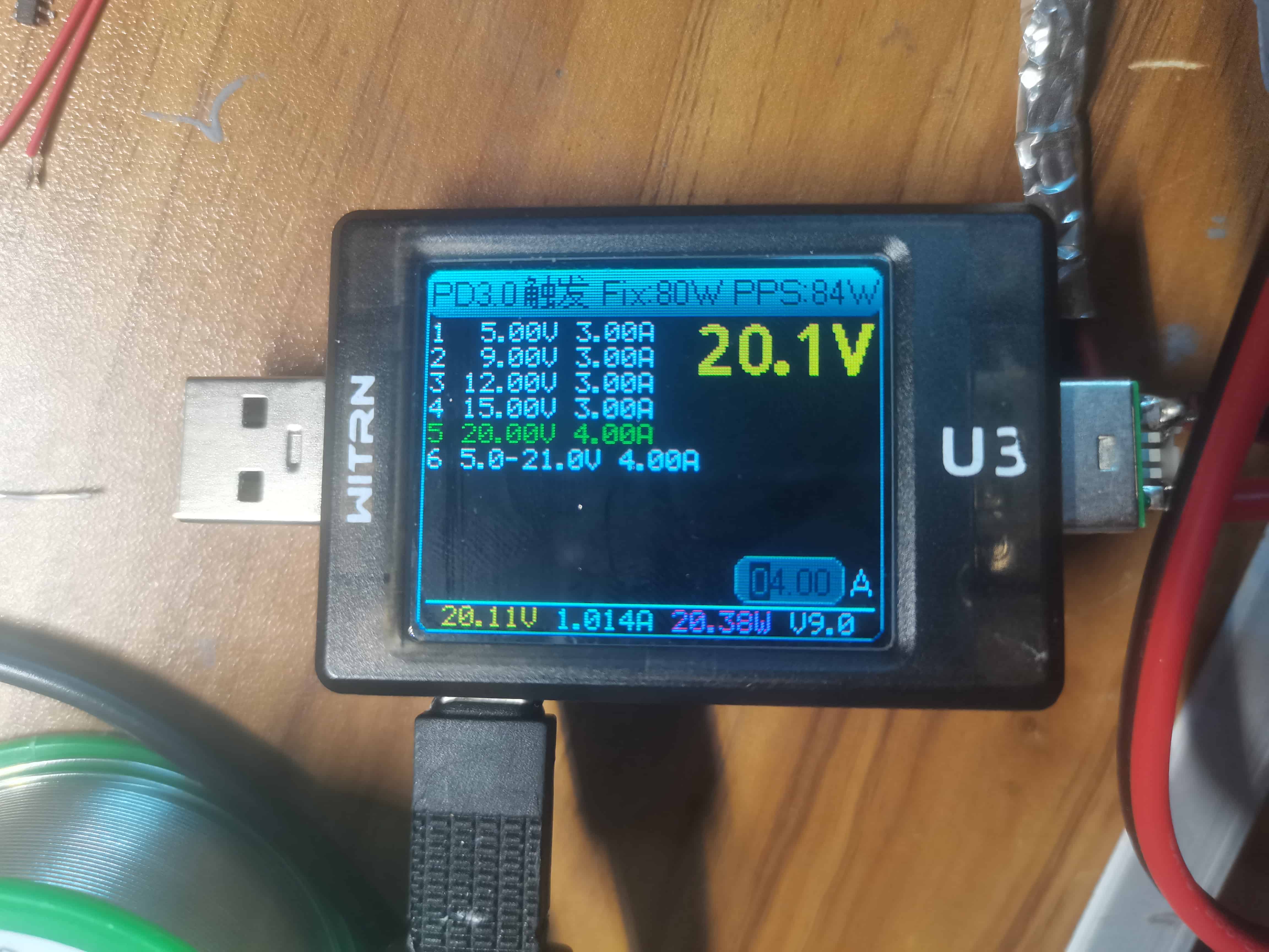
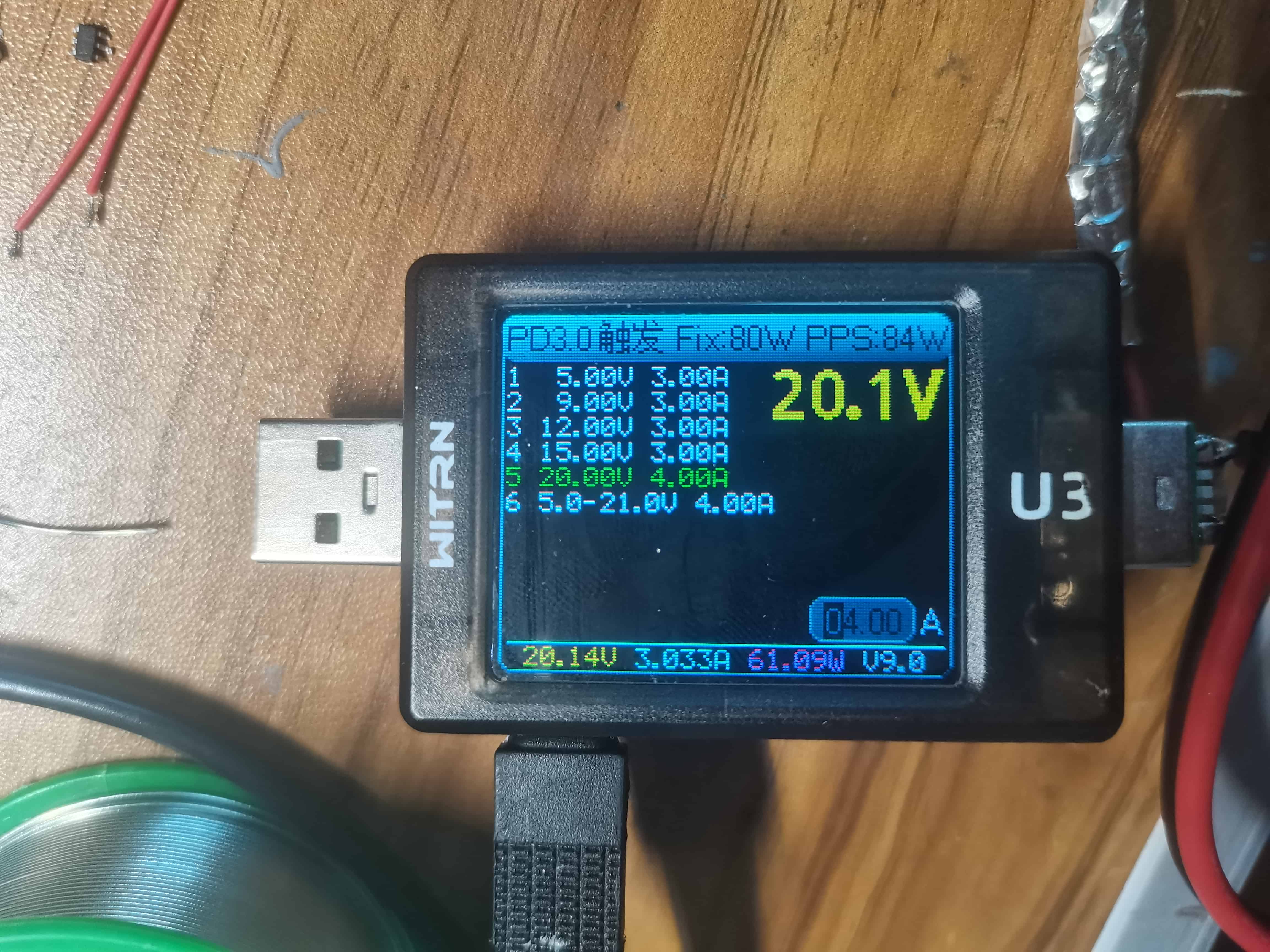
Port C1 (with included cable):

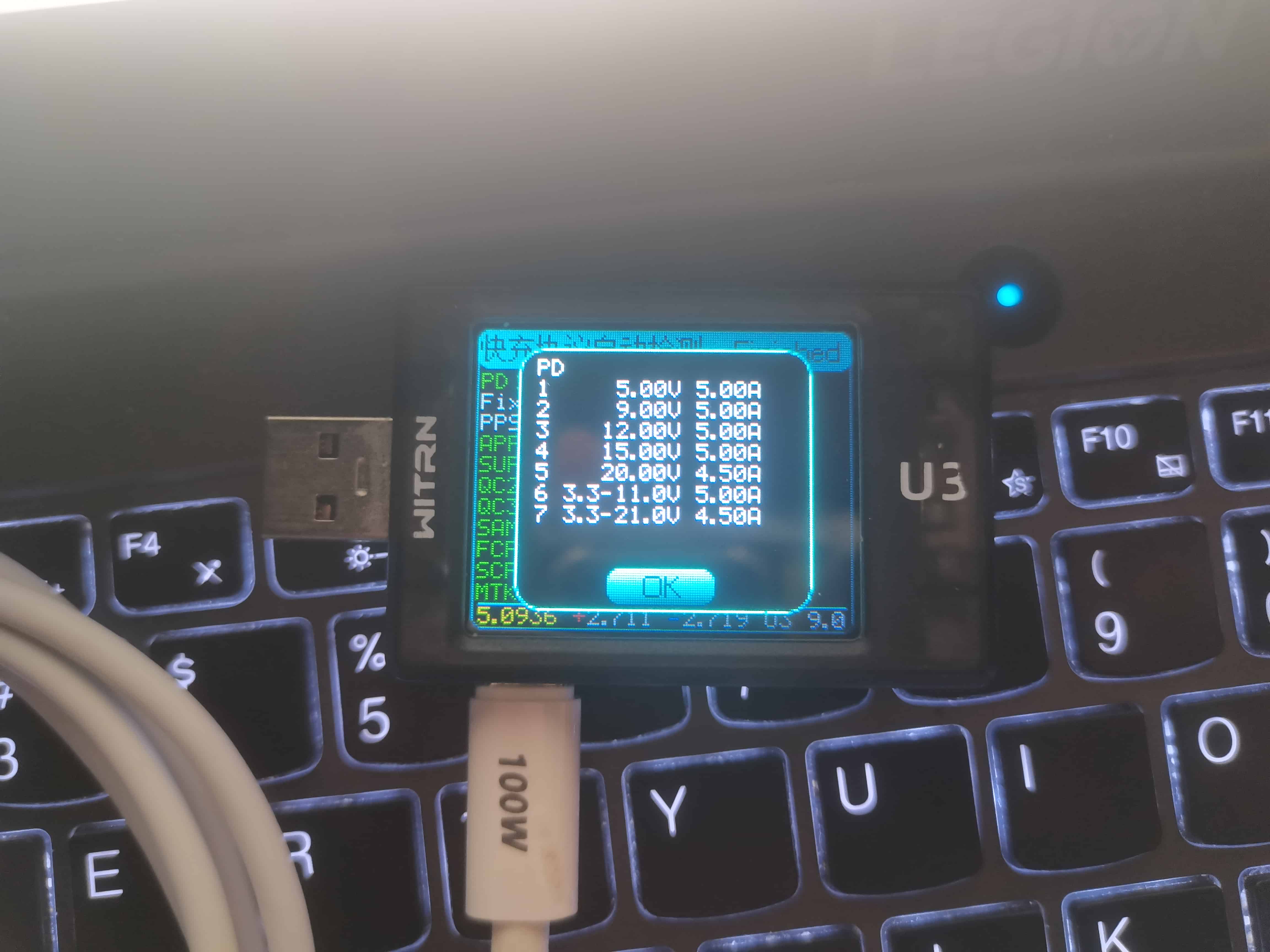
Port C1 PDO:

Port C2 (using EMARKER cable):
Port C2 PDO:
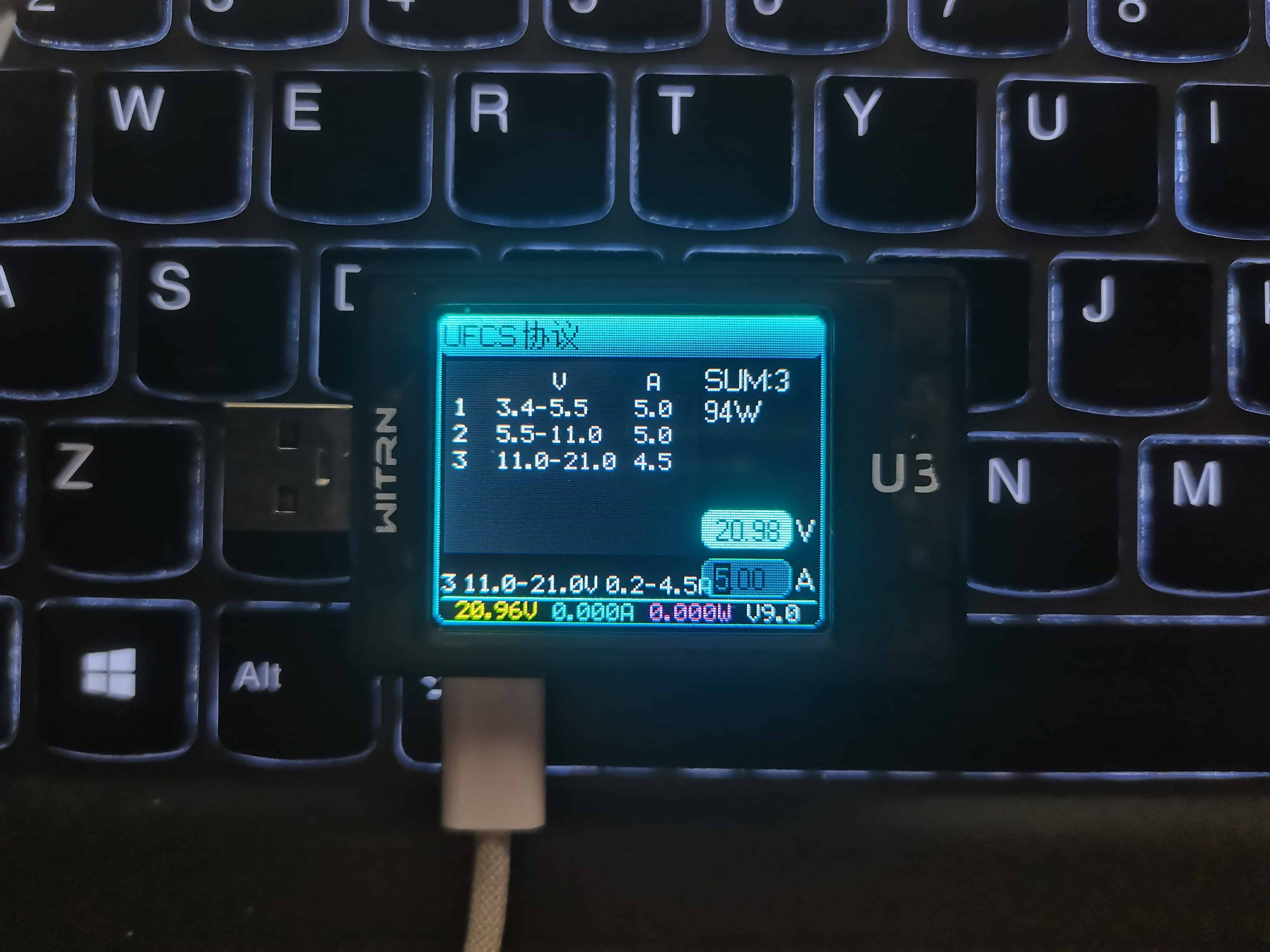
Port C UFCS (both ports are the same):
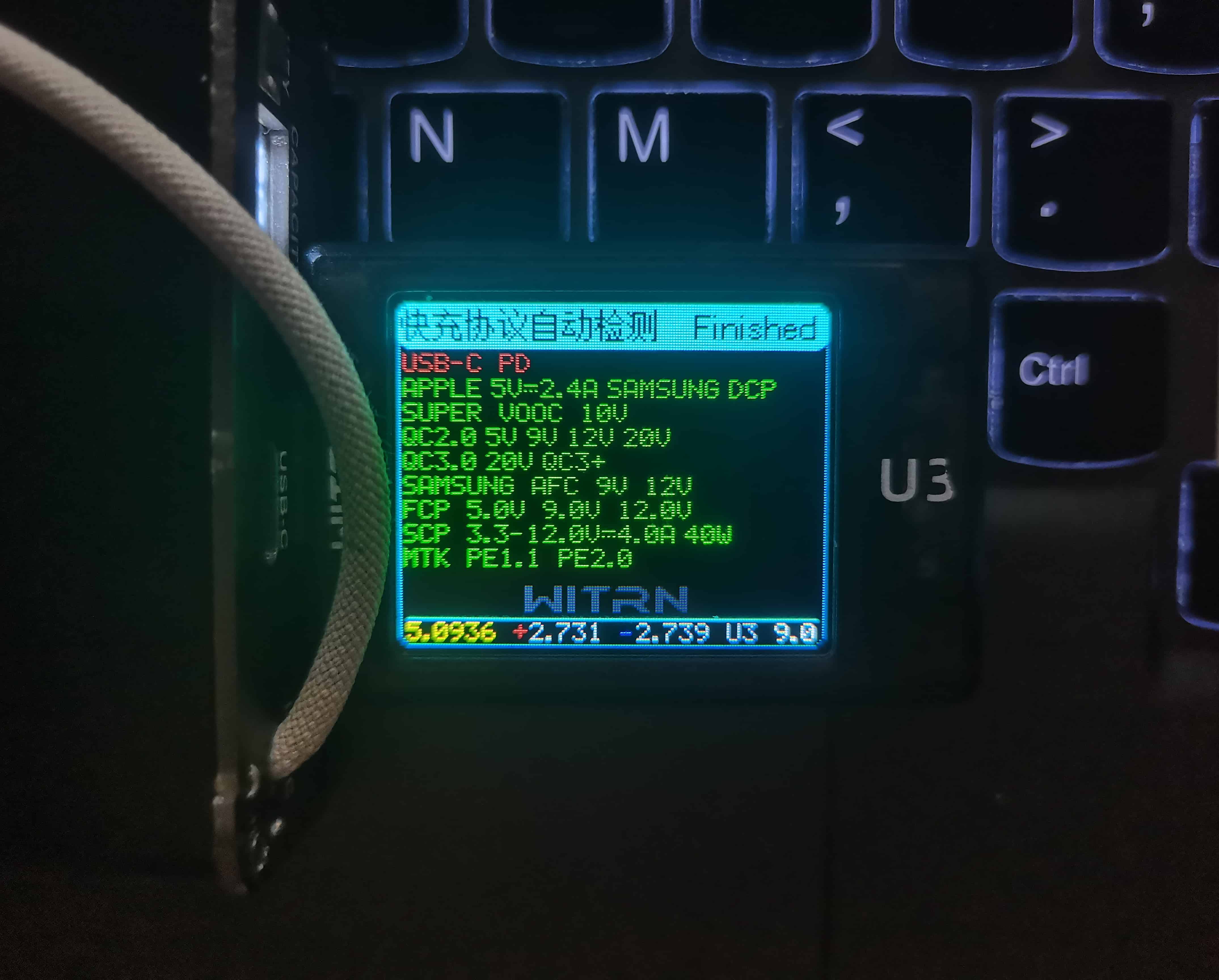
Port A Fast Charging Protocol:
Port A UFCS:

Charging/Discharging Energy and Casing Temperature Rise Test:
Charging:
60W Charging: 55.68Wh 35.5°C -> 44°C (NTC high temperature protection) -> 45.5°C (fully charged)
30W Charging: 55.95Wh 32.2°C -> 39.2°C (fully charged)
18W Charging: 55.95Wh Temperature rise 0°C (cannot be measured)
Discharging:
80W Discharging: 43.75Wh 32.8°C -> 55.8°C (maximum temperature)
60W discharge: 44.99Wh 31.6°C -> 51.7°C (maximum temperature)
20W discharge: 47.38Wh 32.6°C -> 34.2°C (maximum temperature)
Efficiency:
60W: 44.99/55.68 = 80.8% √(89.9%)
20/18W: 47.38/55.95 = 84.7% √(92.0%)
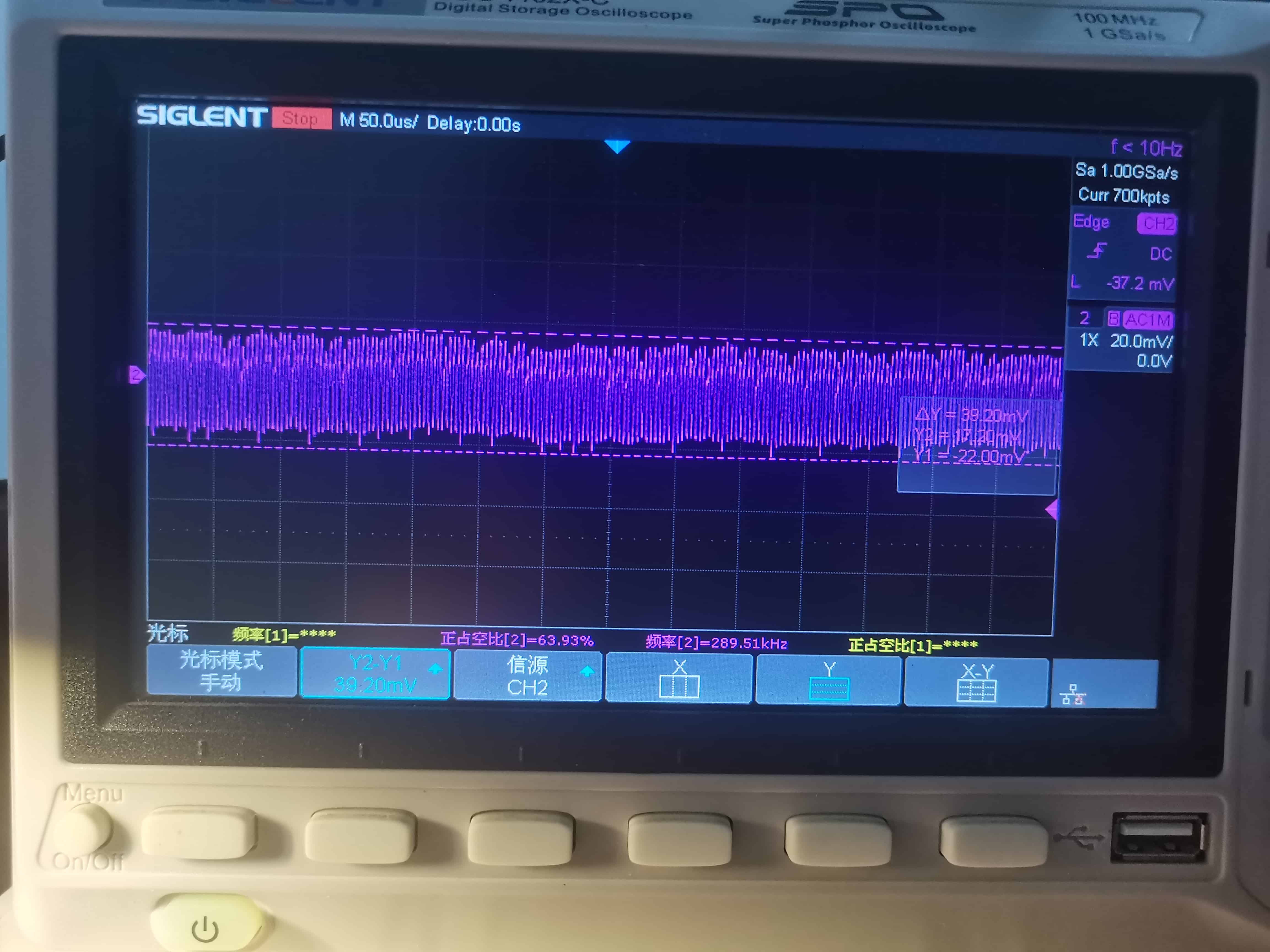
Output ripple test:
No load 40mV:
20W 45mV:
60W 90mV:
80W 118mV:
Static current test:
After the microcontroller enters stop mode: 61uA.
Microcontroller operation, digital tube lighting: 8.7mA.
Three options:
In this design, the microcontroller main control, LED lighting, and built-in wiring are three optional circuits.
For how to modify the schematic and select the PCB when choosing between them, please refer to the last page of the schematic (microcontroller section).
Optional:
Battery: 3 21700 batteries, spot-welded into 3 series according to the method on page 3 of the schematic (protection board section).
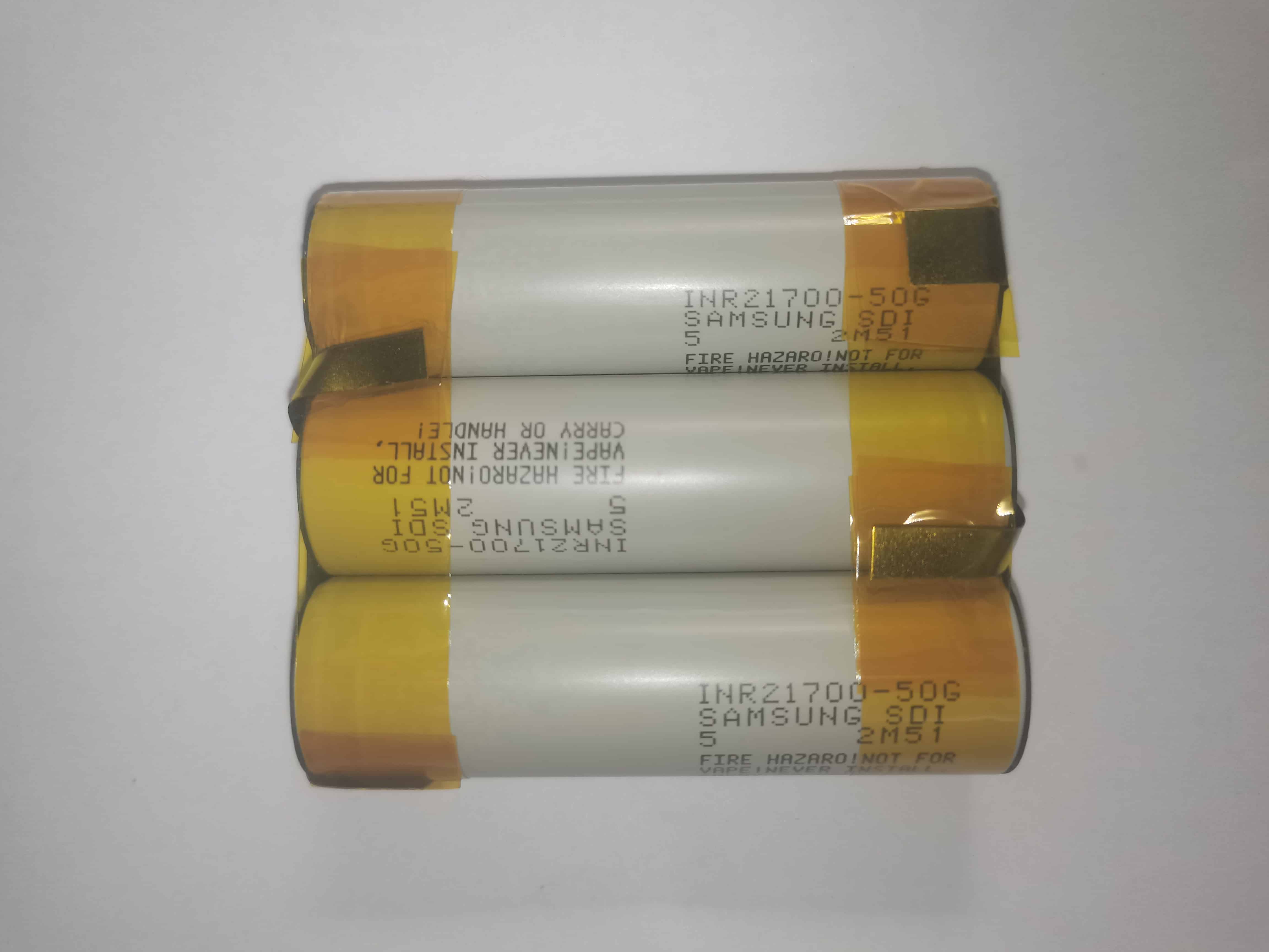
I chose 3 salvaged batteries. Samsung 50G, moderately priced, purchase link: Disassembled Samsung INR21700-50E lithium battery 3.6V suitable for high-power flashlights and electric vehicles 21700 cells - Taobao (taobao.com).
Other batteries such as Samsung 50S, 50E, and Lishen LA can also be used. Modify the battery configuration resistor or the power limit in the sw63066.h file according to the battery's charge and discharge capacity.
Casing: 71*27 split aluminum casing, choose your favorite color, length 100mm, see attached size diagram. Purchase Links:
Aluminum Alloy Shell, Aluminum Profile Shell, Instrument Shell, Battery Box, Metal Shell, Controller Aluminum Shell, Aluminum Box 71
*27 - Taobao (taobao.com) Aluminum Alloy Box, Aluminum Profile Shell, Split Aluminum Shell, Custom Battery Box Shell, Circuit Board Shell, Opening 71*27 - Taobao (taobao.com)
Inductor: RM Flat Copper Wire Inductor (as shown), inductance value selected 4.7uH.
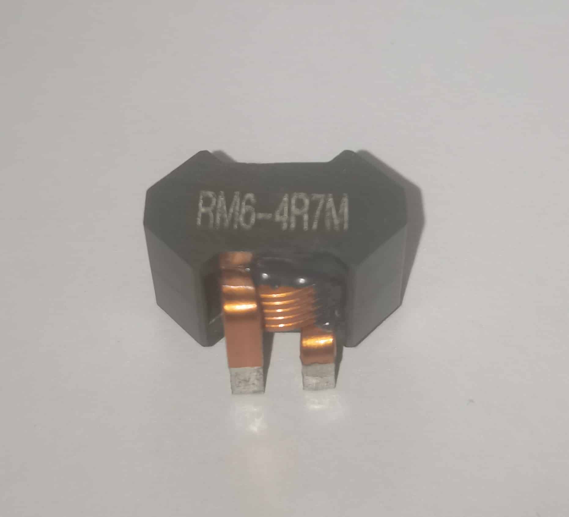
Purchase Links: High Current Flat Copper Wire Inductor 100A RMPQ Filtering Energy Storage Direct-Through Magnetic Core Wound Power Inductor Coil - Taobao (taobao.com)
LED Boost Inductor Selection 6.8uH 0650 (5mm height), choosing 0630 may have saturation risk
. Included cable: It is recommended to use a high-quality cable with an inner metal wire shield. Braided cable is more durable than TPE cable.
The cable diameter should not exceed 3.5mm, and after heat shrink tubing, it should not exceed 4mm to fit into the holes on the panel. You can also modify the PCB file to increase the hole diameter to fit your cable.
I used a 50cm dual USB-C short cable (found through a bargain), but it is currently discontinued.
Capacitors: Choose MLCCs with a voltage rating of 25V or higher. Due to DC bias, the lower the voltage rating of the MLCC, the higher the capacitance required. For example, 25V requires 22uF; 50V only requires 10uF.
Solid capacitor height is recommended to be below 8mm.
SW6306 chip: There are two models: SW6306 and SW6306V. The latter supports the VOOC protocol, but if you choose to use a microcontroller for control, there is no need to distinguish between them.
Compared with other 100W integrated power bank chips, SW6306 is cheaper (7 yuan/piece), has strong driving capability, and supports the most protocols, far ahead of others!
Microcontroller: The Hezhou AIR001, purchased a year ago and now gathering dust, was chosen. Given Hezhou's business shift and increased difficulty in procuring chips, the compatible PuRan PY32F002AF15P could also be selected.
BM3451: The version with the suffix TJDC-T28A was chosen, featuring passive equalization; the common TNDC suffix version is not recommended as its low-voltage shutdown voltage is too high, affecting discharge capacity.
3570 LED: 10W specification selected. Purchase link: Imported 20W six-core white SMD 3570 aftermarket car headlight modification high-power LED beads 9V - Taobao (taobao.com)
Thermal Pads: Purchase 2mm thick silicone thermal pads and cut them yourself.
Purchase link: Thermally Conductive Soft Silicone Sheets, CPU Heatsinks, LED Power Heatsinks, PCB Circuit Board Thermal Insulation - Taobao (taobao.com)
Production:
Determine which functions you need and which components do not need to be soldered. See the last page of the schematic diagram for details
. Clone the project and modify the files as needed.
According to the schematic diagram and BOM, refer to the component selection section to purchase components.
Open the PCB in the editor, select the required board, and assemble or separately prototype
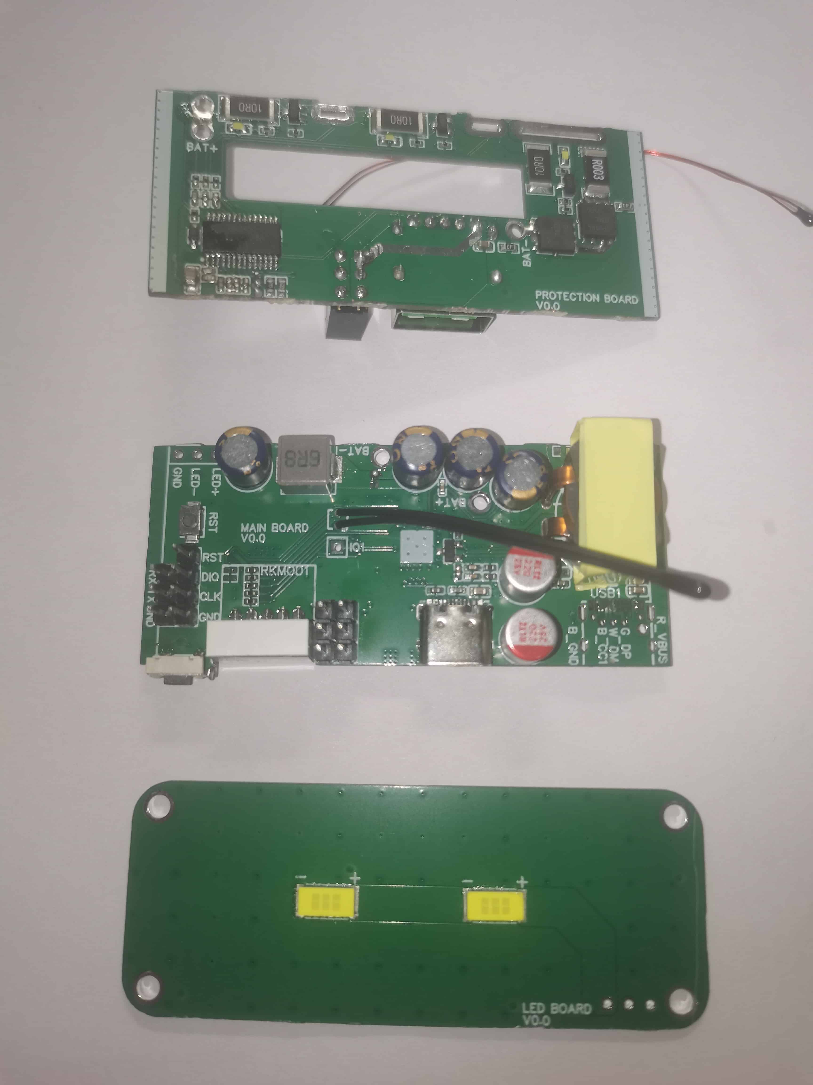
to obtain the PCB:

Solder the main board, paying attention to the LED polarity. The digital tube needs to be bent 90 degrees. Soldering:
Wrap 3 turns of high-temperature tape around both ends of the battery to prevent short circuits with the casing; Cut the thermal pads as shown (to support the battery). Both sides of the casing need them: Insert

the protection board into the aluminum casing groove and solder it to the battery in order of voltage from low to high. Connect:
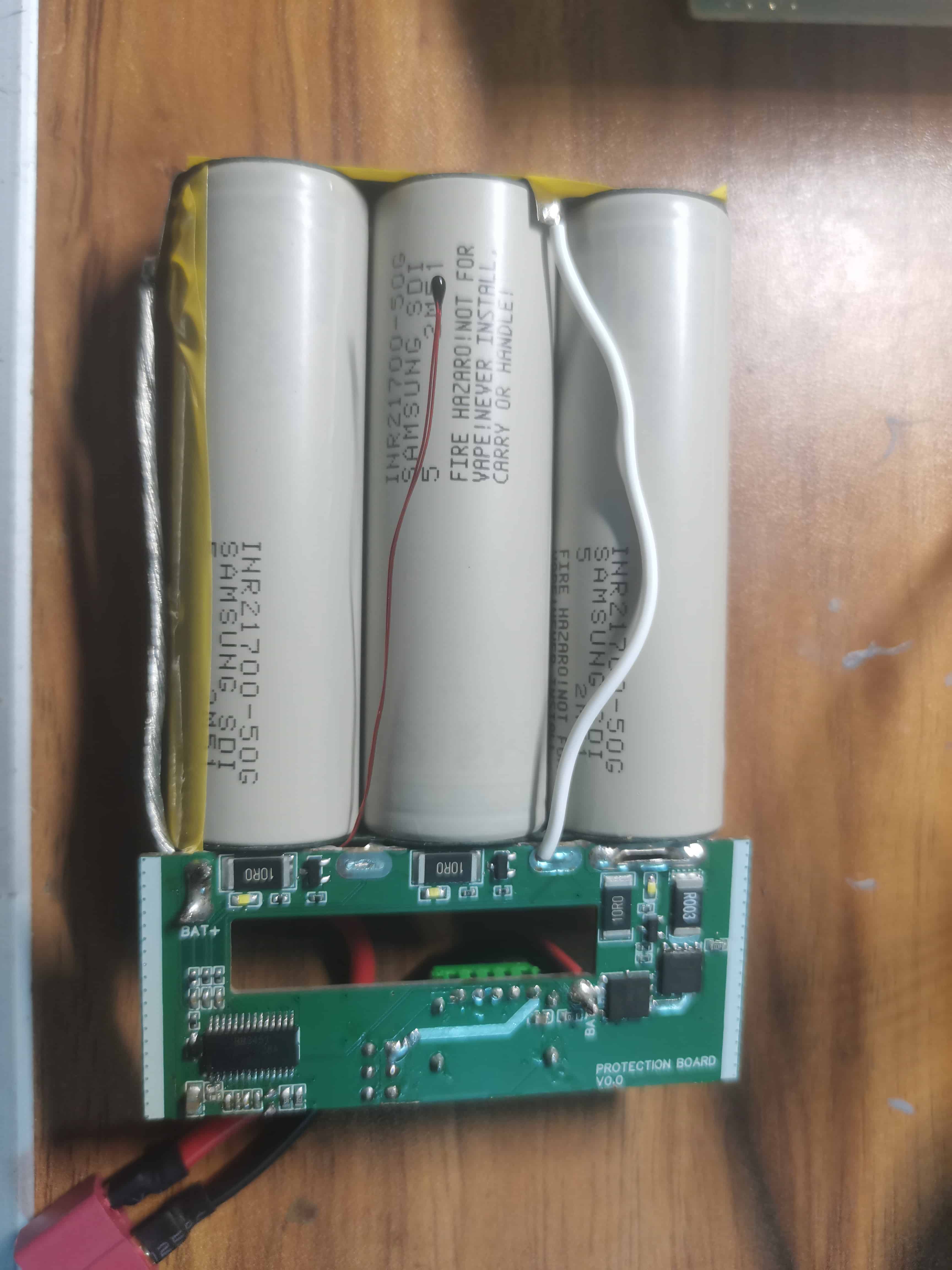
Position the thermistor so that it is between the two batteries when the cover is closed.
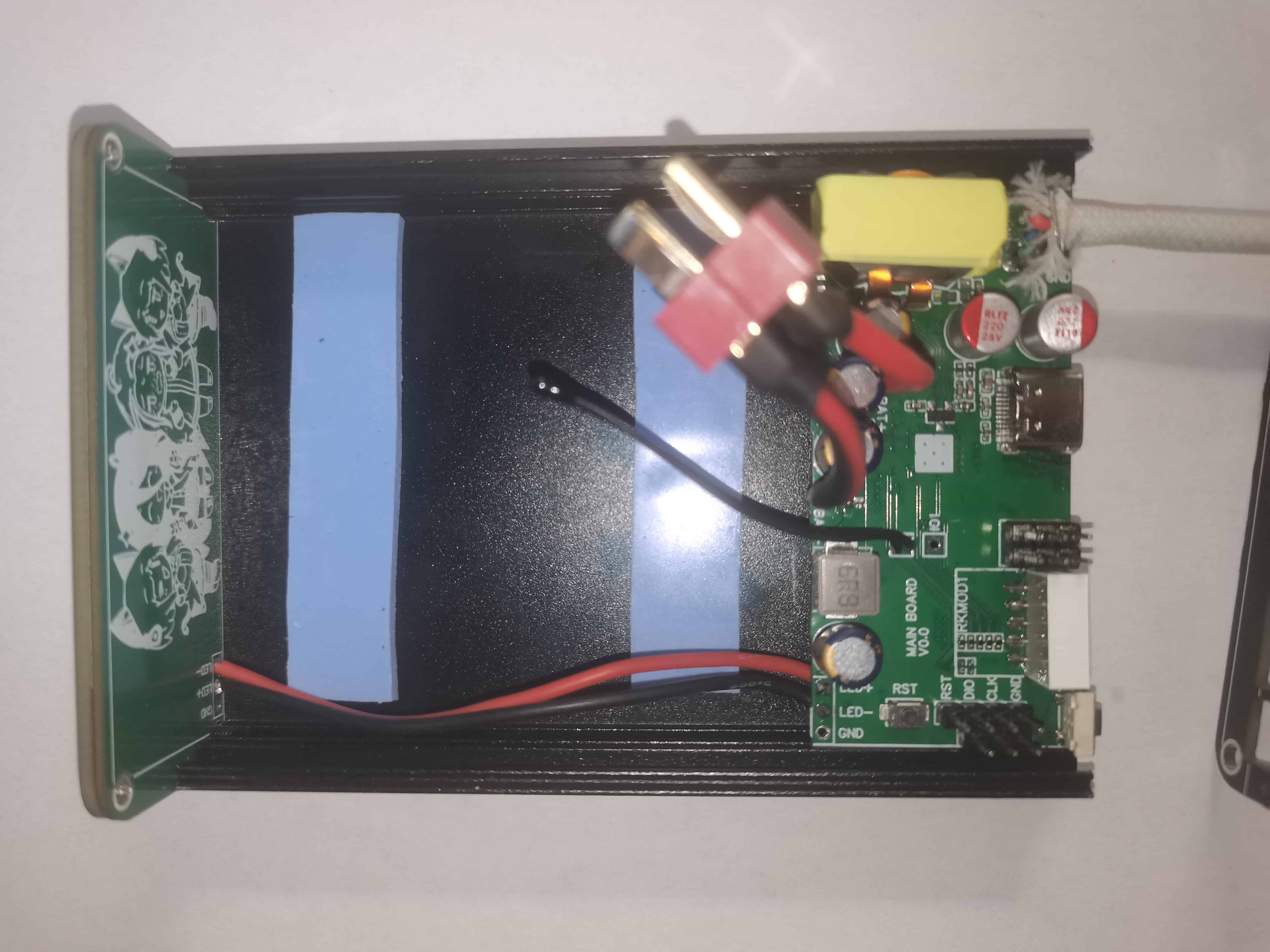
Solder a wire of sufficient diameter and a suitable plug (for easy disassembly and assembly; the picture shows a T-plug) to the battery interface of the main board and protection board.
Assemble the lower half: Insert the main board into the slot, fix the LED board to the back with screws, and connect the main board and LED board with a wire of less than 20AWG. Use two layers of 2mm thermal pads under the inductor to conduct heat to the outer casing.
Use a multimeter to test whether the protection board has voltage output and whether the main board battery terminal and interface terminal are short-circuited.
Connect the main board and protection board and see if the digital tube lights up
(included wire). Take a suitable length (15~30cm), cut the wire, and put it into a 10mm long, 6mm diameter heat shrink tubing, but do not heat shrink it. Thread the wire into the pre-drilled hole on the panel with the C end facing out
(included wire). Cut the wire end and find VBUS. Solder the five wires (GND, CC1, DP, DM) to the board according to the PCB silkscreen. After soldering, slide heat shrink tubing over the wire ends and heat shrink. Ensure the heat shrink tubing is inside the panel hole
before sliding the included wires. If there is a shielding mesh, it is recommended to solder half to the motherboard's C-port outer pad and half to the edge of the panel hole to increase mechanical strength
(microcontroller). Prepare DAPLINK. Install KEIL and DAPLINK drivers on your computer. Connect DAPLINK to the motherboard header according to the readme.md in the software folder. Open the uvproj file, compile and download
(microcontroller). If a connection failure is displayed, check the connection cable. Use a short connection cable or simply hold the connection cable to prevent external signal interference.
After downloading (microcontroller), press the RST button to open the serial port assistant and observe the output (baud rate 115200).
Test the charging and discharging power and protocol to ensure they are normal. Test the digital tube power display and fast charging display to ensure they are normal.
Test the LED lighting function to ensure it is normal.
For final assembly, the plug and socket connecting the motherboard and the protection board can be inserted into the slot on the protection board. When closing the aluminum shell, align the 2*3pin socket on the protection board with the plug on the motherboard
and tighten the screws.
Precautions:
Lithium batteries are flammable and explosive. Handle with care, disconnect the circuit in time, and avoid overheating, overcharging, and over-discharging.
Contains a large number of 0402 components and QFN chips, requiring certain soldering skills.
The PD protocol cannot achieve an output exceeding 5A/60W without an EMARKER line/5A line. The built -in
wire must be sheathed, otherwise it will not be very durable.
Some of the schematic diagrams are from older versions and have defects, but these have been fixed in the release version. Therefore, the finished product may differ slightly from the diagram.
The backplate contains some parameter information, which you can modify according to your preferences, such as adding certification marks for easy loading. Please
refer to the schematic diagrams, PCB annotations, and readme.md file.


 京公网安备 11010802033920号

 GRM0335C1H2R8BA01


