Project Overview:
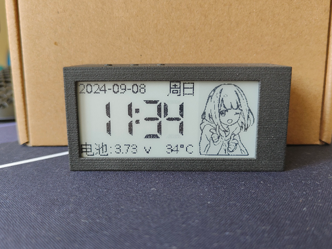
This project uses the ESP32C3 chip and is developed based on Arduino. It features a clock and night light functions. The front of
the screen
is a 2.9-inch e-ink clock displaying year, month, day, weekday, time, battery voltage, internal temperature, and a custom image.
The back is a light board with eight 0.2W LEDs in series and two in parallel, providing a maximum power of 3.2W.
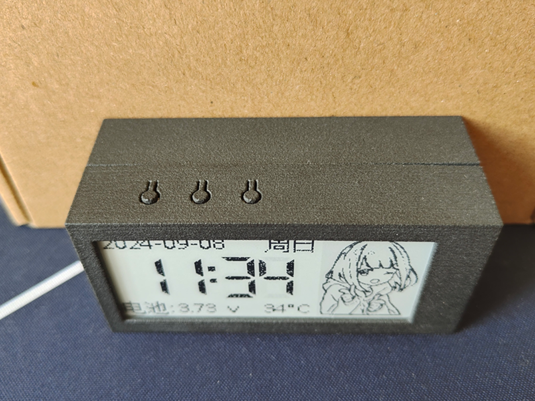
The three buttons on the back, from left to right, are: LED brightness adjustment, manual NTP time update, and software restart. The dimming function has three fixed levels: 20%, 50%, and 100%. The other two buttons are for preventing accidental touches; they require a quick double press to activate.
The Type-C port on the left is for charging and communication. Charging is 5V 1A by default, and the ESP32C3 can be debugged through this interface.
Project Parameters:
This project uses a WFT0290CZ10 e-ink screen with a resolution of 296*128.
The e-ink driver uses the EPaperDrive library and a hardware SPI driver; theoretically, any screen in the EPaperDrive library can be used.
The night light section uses the LGS63032 as a constant current boost chip, sharing a 4kHz PWM with the buzzer for dimming. A buzzing sound at low duty cycles is normal.
The battery voltage sampling section uses the internal calibration parameters of the ESP32C3, with acceptable accuracy.
Temperature sampling uses a 10K 3950B NTC thermistor, mainly used to detect the temperature of the light board; excessively high temperatures will reduce the LED's duty cycle.
The charging section uses the classic 4056 chip, consuming only a few µA of current when not charging.
Principle Analysis (Hardware Description):
This project consists of the following parts: main control unit, LED lighting unit, screen unit, power supply unit, and battery charging/discharging unit. This project mainly obtains NTP time through the network and synchronizes it with the RTC clock, periodically updating the screen display content, and then combining this with button presses to complete the corresponding functions.
I won't go into detail about the main control unit, screen, and power supply unit; I'm a beginner and don't understand them either~( ̄▽ ̄)~.
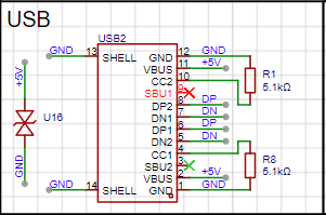
Type-C Circuit:
A TYPE-C-16P interface is used as the power supply interface. The corresponding USB data pins are connected to the corresponding USB pins on the S3 (USBDN IO18, USBDP IO19), allowing direct USB download and debugging without conversion to serial signals. 5.1K pull-down resistors are added to the CC1 and CC2 pins for easy identification and configuration by different hosts.
LED Lighting Circuit:
An LGS63032 is used as the constant current boost controller. The constant current depends on the value of R25 (I=0.2V/1.6Ω). It is recommended to design the lamp board according to the parameters in the datasheet to achieve the highest conversion efficiency. When redesigning, pay attention to the rated current of the inductor. Testing shows that 3.2W of power is suitable for the lamp board.

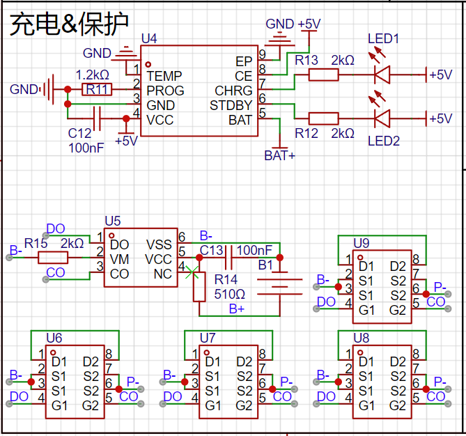
Battery Charging/Discharging Section:
The battery charging uses the classic 4056 chip. The datasheet indicates that the chip's power consumption is below 10uA, and it can reach as low as 2uA when not plugged in. The charging current in the diagram is set to 1A. When purchasing 18650 batteries, pay special attention to the battery charging current!
The lithium battery protection uses DW01+8205 MOSFETs, which is a cost-effective and mature solution. Only four 8205 MOSFETs are needed; the two extra ones on the PCB can be left unsoldered.
Software code:
//External libraries used only: EPaperDrive library
//arduino 2.3.2
//ESP32 3.0.3
The following are Arduino settings; please ensure all settings are consistent.

Appearance:

Version
V1.0.0 has not yet implemented low-power processing; a 2600mAh battery will last approximately one week.


 京公网安备 11010802033920号

 1539-52F


