An ADC (Analog-to-Digital Converter) is an indispensable key component in electronic systems. It converts continuous analog signals into digital signals, enabling digital processing and analysis. ADCs play a crucial role in signal conversion, measurement and data acquisition, control system input, and communication and signal processing. Their widespread application promotes the intelligent and precise control of electronic equipment across various industries, making them a key factor driving modern technological progress.
Learning to design and build a digital voltmeter and ammeter is highly beneficial for enhancing personal professional skills. This digital voltmeter and ammeter project covers multiple aspects, including microcontroller circuit design and implementation, signal acquisition and processing circuit design, user interface development and optimization, and product appearance design. It integrates knowledge from multiple fields such as electronics, microcontroller programming, circuit design, and industrial design. Considering the learning pace and knowledge absorption capacity of beginners, we have specially launched this introductory-level digital voltmeter and ammeter project, which is very suitable for beginners in electronics and those who want to learn more about microcontroller applications. This project boasts several highlights:
It adopts a core board plus expansion board design concept, utilizing plug-in components to simplify learning and deepen exploration;
the core board uses the domestically produced Wuhan Xinyuan Semiconductor CW32 as the main controller, while also being compatible with other similar development boards; however, the CW32 offers significant advantages.
The project is highly comprehensive and practical, and once completed, it can be used as a desktop instrument.
The project offers abundant learning materials, including circuit design tutorials, PCB design, code programming, and training for engineers' debugging skills.
The digital voltmeter and ammeter combine ADC technology with circuit measurement principles, accurately converting analog voltage and current signals into digital displays for easy reading and analysis by electronic engineers. This device not only improves the accuracy and efficiency of circuit measurements but also helps engineers better understand circuit behavior, serving as a powerful tool for electronic design and troubleshooting, and playing a crucial supporting role in the work of electronic engineers. In product application, the digital voltmeter and ammeter ensures the accuracy and safety of circuit design while also providing strong support for product quality control and subsequent maintenance.
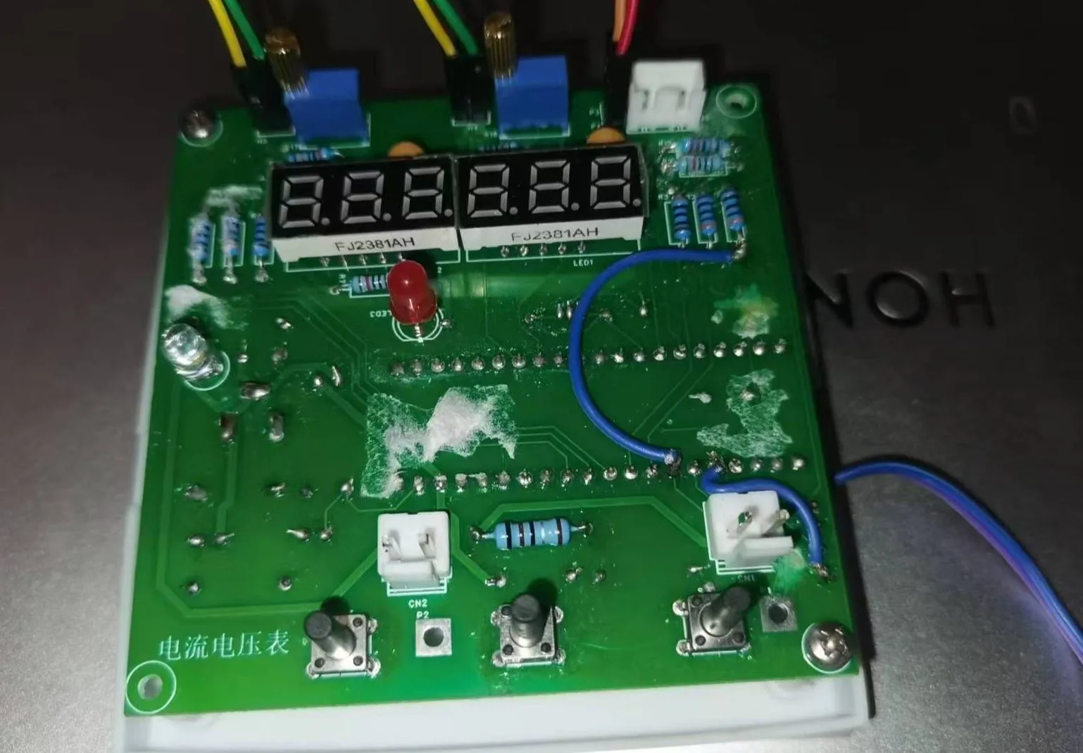
This project utilizes the LCSC CW32F030C8T6 development board and expansion boards for power supply and current/voltage simulation circuits to design and build a voltage and current meter. Mr. Li from VeriSilicon Semiconductor provided detailed instruction. The project used LCSC EDA software for schematic, PCB, and enclosure design.
LDO (Low Dropout Linear Regulator) Selection:
This project uses an LDO as the power supply. Considering that most voltage meter products are used in industrial scenarios with 24V or 36V power supplies, the SE8550K2 with a maximum input voltage of 40V was selected. The main reason for not using a DC-DC step-down circuit to handle the large voltage drop is to avoid introducing ripple interference from the DC-DC circuit during the design process; a secondary reason is to reduce project costs.
Filtering Function: The capacitors surrounding the LDO, especially the input capacitor, can effectively filter out ripple interference from the preceding power supply.
Improved Load Transient Response: The output capacitor plays an important role in improving the load transient response. When the load current changes drastically, the LDO has an adjustment time. During this time, the output capacitor acts as a temporary power supply, providing the circuit with the necessary current and preventing the output voltage from being pulled too low. A larger output capacitor value can further improve the LDO's transient response to large load current changes.
The CW32's key advantages in this project
include: Wide operating temperature range: -40~105℃;
Wide operating voltage range: 1.65V~5.5V (STM32 only supports 3.3V systems)
; Strong anti-interference: HBM ESD 8KV; All ESD reliability reaches the highest international standard level (STM32 ESD 2KV);
Project focus - Better ADC: 12-bit high-speed ADC, achieving ±1.0LSB INL 11.3ENOB; Multiple Vref reference voltages... (STM32 only supports VDD=Vref);
Stable and reliable eFLASH technology. (Flash0 waiting).
Voltage sampling circuit:
This project uses a voltage divider circuit to achieve high voltage acquisition, designed to acquire voltages up to 100V, currently configured to acquire voltages of 0-30V.
This project requires a combination of hardware and software to achieve this function. When we first use the ADC_IN11 channel mentioned earlier to measure voltages up to 30V, if the measured voltage is within 0~3V, then use the ADC_IN9 channel for measurement. At this time, due to the reduced voltage division ratio, the measurement accuracy is greatly improved. When learning the corresponding circuit measurement principle, considering that users may not be able to easily build external circuits for testing and debugging, and adhering to the principle of ease of development of the development board, a circuit is specifically set up to simulate voltage measurement, measurement calibration, and measurement calibration auxiliary circuits. No external voltage is required. Use a multi-turn adjustable potentiometer (R18) to divide the development board's power supply voltage and connect it to the +V network through the development board's internal circuitry. Note that H4 needs to be shorted at this time; a jumper cap is sufficient, and a long-handled jumper cap is recommended. Do not short H4 if this function is not used.
This project uses a low-side current sampling circuit for current detection. The low side of the sampling circuit shares a common ground with the development board's meter interface
to simulate current measurement, measurement calibration, and measurement calibration auxiliary circuits.
When using this function, do not solder the R0 sampling resistor. If this function is not used, please disconnect JP2.
Current sampling essentially involves acquiring the voltage drop across the sampling resistor when current flows through it, i.e., acquiring the voltage value. This circuit uses R17 to provide a voltage value in the range of 0~0.238V (5V ÷ 210K * 10K), which is connected to the chip's current sampling pin via the I+ network.
In actual use, the voltage at I+ simulates the voltage drop across the unsoldered 100mΩ sampling resistor. At this time, the simulated measured current value Imeasured = this voltage value Vi+ ÷ 100mΩ, which is also exactly equal to the measured voltage value multiplied by 10. That is, it provides a simulated current measurement of 0~2.38A.
Set a multimeter or high-precision benchtop digital multimeter to the voltage measurement port, with a range within 3V. Insert the black negative probe into the T_GND interface next to the voltage measurement terminal, and the red positive probe into the TI+ port for current measurement to measure the actual voltage value of I+. Therefore, this circuit can not only complete the above design tasks, but also allow for a direct test to demonstrate the accuracy of the MCU's ADC peripheral. Users can write their own programs to verify this.
This project uses digital tubes as the display unit.
Two 0.28-inch three-digit common-cathode digital tubes are used as display devices. Compared to displays, digital tubes have better visibility in complex environments. The brightness of the digital tubes can be increased by using smaller current-limiting resistors depending on the actual usage environment. Furthermore, digital tubes have better mechanical properties and are not as easily damaged by external forces as displays. They are widely used in industrial applications requiring stability and reliability. From a development board learning perspective, this makes it easier to learn electronic measurement principles and related development in a targeted manner.
In this project, after actual testing, the current-limiting resistors (R1~R6) of the digital tubes were configured to 300Ω. The corresponding brightness, whether for red or blue digital tubes, showed good visibility and was soft and not glaring.
This project adds an extra TL431 circuit to provide a 2.5V reference voltage, which can be used to provide an external voltage reference for the chip to calibrate the AD converter. From a product design perspective, due to the inherent ADC performance advantages of the CW32, this circuit is not necessary. This circuit was designed on the development board to learn the relevant application principles.
Phase Compensation: For adjustable output LDOs, the capacitor connected in parallel with the resistor (called the feedback capacitor CFB) provides leading phase compensation, increasing oscillation margin and improving load transient response. Zeroing CFB and R1 contributes to loop stability.
Oscillation Prevention: Proper capacitor configuration helps prevent oscillations in the LDO circuit, ensuring stable circuit operation.
Ripple Suppression: Capacitors in LDOs also help improve the power supply rejection ratio (PSRR), reducing the impact of power supply noise on circuit performance.
Startup Inrush Current Control: The input capacitor acts as a temporary power source for startup inrush current during LDO startup, preventing the input voltage from being pulled low and affecting the stability of the preceding power supply.


 京公网安备 11010802033920号

 NRLM682M160V20X25F


