Project Introduction:
This project is a complete replication of the Diwenxing CW32 development board training camp project. Learning is achieved through the project, and the final product, a voltmeter and ammeter, is quite practical.
Most components use through-hole connectors for easy soldering. Two issues arose during procurement: 1) the through-hole resistor R0 (100mΩ) was out of stock, so it was replaced with a surface-mount resistor with the same parameters. 2) To save on shipping costs, all components were sourced from a warehouse in Jiangsu, resulting in slight differences in the color of the digital display and some resistors compared to the original BOM.
Note: When replacing through-hole components, D (diameter) can be slightly larger or smaller, but L (length) should be as similar or slightly smaller as possible to ensure insertion into existing holes.
Project Functionality:
This design is a digital voltage and current meter based on the Diwenxing CW32F030C8T6 development board. It features three independent buttons and two 3-digit LED displays, capable of simultaneously measuring voltage and current.
Project Parameters
: Based on the Diwenxing CW32F030C8T6 development board, this design is essentially a direct
replica It uses two 3-digit LED displays; the top row shows voltage, and the bottom row shows current.
With a calibration function, calibration is performed using buttons, defining five working modes. The K1 button switches between display modes. The K2 button sets the parameter value for the corresponding mode and saves it to FLASH. The K3 button returns to mode 0.
Principle Analysis (Hardware Description):
This project consists of the following parts: DC power input section, MCU section, voltage sampling circuit, current sampling circuit, LED display, LED indicator section, button control section, and voltage calibration section.
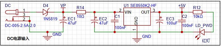
DC Power Input:
A DC-0052 interface is used as the power supply interface; 5-12V DC power supply is recommended.
This project uses an LDO (Low Dropout Linear Regulator) as the power supply. Considering that most voltmeter products are used in industrial scenarios with 24V or 36V power supplies, the SE8550K2 with a maximum input voltage of 40V was chosen. The main reason for not using a DC-DC step-down circuit to handle the large voltage drop is to avoid introducing ripple interference from the DC-DC converter during the design process; a secondary reason is to reduce project costs.
MCU section:
As this is a CW32 training camp, the CW32F030C8Tx development board (core board) was naturally chosen as the main controller. The training camp's documentation provides a fairly detailed analysis of the main controller selection, which you can study independently.

Voltage sampling circuit:
The voltage divider resistors in this project are 220K+10K, resulting in a voltage division ratio of 22:1 (ADC_IN11). Range
switching
: An additional voltage sampling circuit was added to this project. Multimeters often have multiple range settings for more accurate measurements. By adjusting different ranges, the optimal measurement accuracy of the measured point within the corresponding range can be obtained.
This project requires a combination of hardware and software to achieve this function. When we first use the ADC_IN11 channel mentioned earlier to measure voltages below 30V, if the measured voltage is within 0~3V, then use the ADC_IN9 channel for measurement. At this time, due to the reduced voltage division ratio, the measurement accuracy is greatly improved. Current
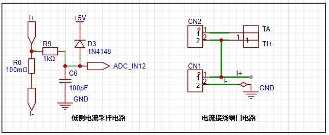
Sampling Circuit :
This project uses a low-side current sampling circuit for current detection. The low-side of the sampling circuit shares a common ground with the development board's meter interface.
Do not solder R0 before the project is completed!!!
The sampling current designed for this project is 3A, and the selected sampling resistor (R0) is 100mΩ.
The selection of the sampling resistor mainly needs to consider the following aspects:
the maximum value of the pre-designed measurement current;
the voltage difference caused by the 3A current sensing resistor in this project; generally, it is not recommended to exceed 0.5V;
the power consumption of the current sensing resistor; a suitable package should be selected based on this parameter. Considering the power consumption (temperature) problem under high current, a 1W packaged metal wire-wound resistor was selected in this project;
the voltage amplification factor of the current sensing resistor: No operational amplifier is used to build the amplification circuit in this project, so the factor is 1.
Then, the current sensing resistor value can be calculated using the above parameters.
Since this project does not use an amplifier circuit, a larger sampling resistor is needed to obtain a higher measured voltage for measurement.
Considering that a larger resistor will result in a larger voltage drop and higher power consumption, a larger resistor cannot be chosen indiscriminately.
This project uses a 1W package resistor, corresponding to a power consumption of 1W.
Based on the above data, a 100mΩ current sensing resistor was selected. According to the formula, *3A100mΩ=300mV, 900mW. **
To cope with different usage environments, especially high current scenarios, the R0 resistor can be replaced with constantan wire or a shunt. The replacement can be chosen according to the actual usage scenario. For safety and educational purposes, this project will not discuss measurements exceeding 3A, but the principle is the same.

Digital tube display circuit:
This project uses two 0.28-inch three-digit common cathode digital tubes as display devices. Compared with a display screen, digital tubes have better recognition in complex environments. Depending on the actual usage environment, a smaller current-limiting resistor can be used to achieve higher brightness of the digital tubes. On the other hand, digital tubes have better mechanical properties and are not as easily damaged by external forces as display screens. In industrial and other applications requiring stability and reliability, this technology is widely used. From a development perspective, it facilitates more targeted learning of electronic measurement principles and related development.
In this project, after actual testing, the current-limiting resistors (R1~R6) for the digital tube were configured to 300Ω, and the green digital tube I used also showed good readability.
Strictly speaking, the current-limiting resistors should be added to the segments; adding them to the digits would affect the display effect. In our actual design, we added them to the digits to save a few resistors, but the impact on the display was not significant. Therefore, we added them to the digits for convenience.
This
project also includes an additional power indicator and an I/O operation indicator.
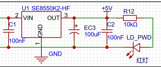
LD_PWD is the power operation indicator (very dim).

Since chip I/O often has a greater current sinking capability than a current pulling capability, LED1 is designed to be active low (bright).
To reduce the current consumption of the LED, some LED brightness was sacrificed, and the number of device parameters was reduced. The LED current-limiting resistor was chosen to be 10K.
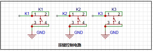
There are various design methods for the button control circuit. Thanks to the CW32's internal I/O ports which can be configured with pull-up and pull-down resistors, the button control circuit on the outside of the chip does not need to be configured. One end of the button is connected to the MCU's I/O, and the other end is grounded. When the button is pressed, the I/O is pulled low.
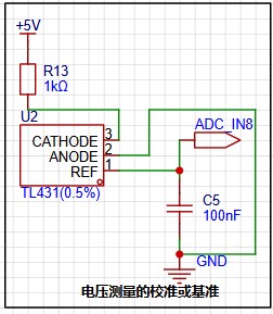
TL431 circuit design for voltage measurement calibration:
This project adds an extra TL431 circuit to provide a 2.5V reference voltage, which can be used to provide an external voltage reference for calibrating the AD converter. From a product design perspective, due to the inherent ADC performance advantages of the CW32, this circuit is not necessary. This circuit was designed on the development board to learn the relevant application principles.
The TL431 is a relatively "old" device, very classic, and widely used; it is still found in many electronic products.
Many beginners may be encountering this device for the first time, so we will briefly explain the principles of this product to help everyone better apply the TL431.
TI defines it by its name as a precision programmable reference. On the first page of the references, we can focus on several key characteristics.
**Precision:** Precision indicates its highly accurate output voltage. The TL431 I used has ±0.5% accuracy, and at room temperature, it measured 2.495V on the board. This is a world of difference in accuracy compared to common Zener diodes. In application circuit diagrams, the TL431 is internally represented by a Zener diode symbol. **
Adjustable Output Voltage:** The adjustable output voltage is between Vref and 36V. In our project, we use the output Vref voltage, which is approximately 2.5V. Therefore, we use 2.5V in the description, which is approximately equal to Vref. **
Sinking Current Capability:** This refers to how much current the output voltage pin can provide. This is greatly influenced by the resistance value (R13) in the application circuit. It should not be less than 1mA. If there is no need for sinking current, do not design the current too high, as this will cause unnecessary power consumption.
...
Important Notes :
R0 (100mΩ resistor) must be soldered only after debugging.
It is recommended to use dry cell batteries (purchase a battery box) for power supply, as this provides a more stable power supply.
For improved accuracy, additional calibration is required.
Refer to the following document: https://wiki.lckfb.com/zh-hans/dwx-cw32f030c8t6/training/voltammeter-bootcamp/voltammeter.html
Physical Images :
Figure 1: Physical Image;
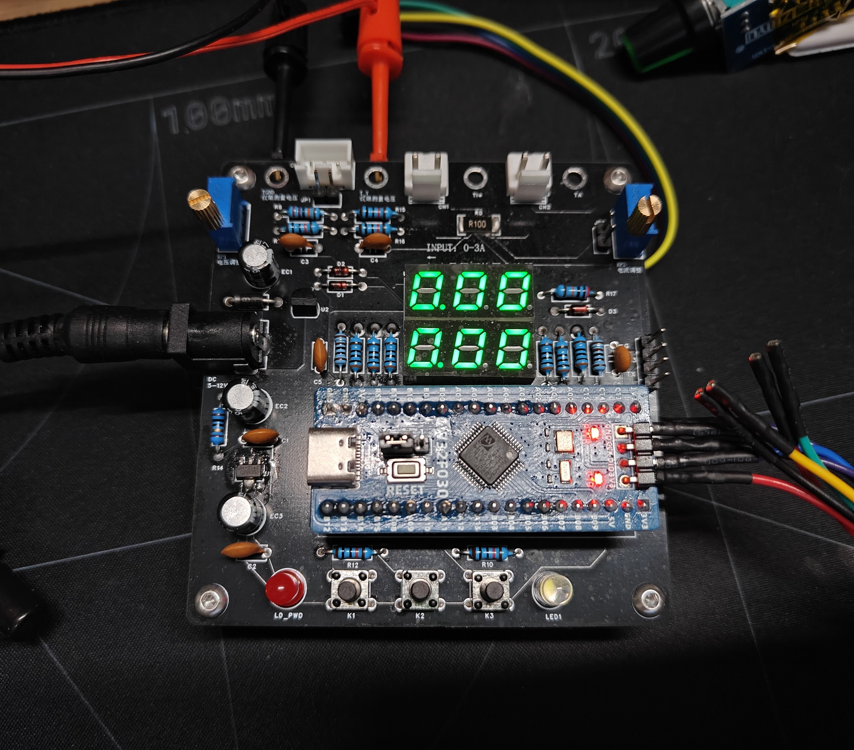
Figure 2: Debugging, without R0 resistor;
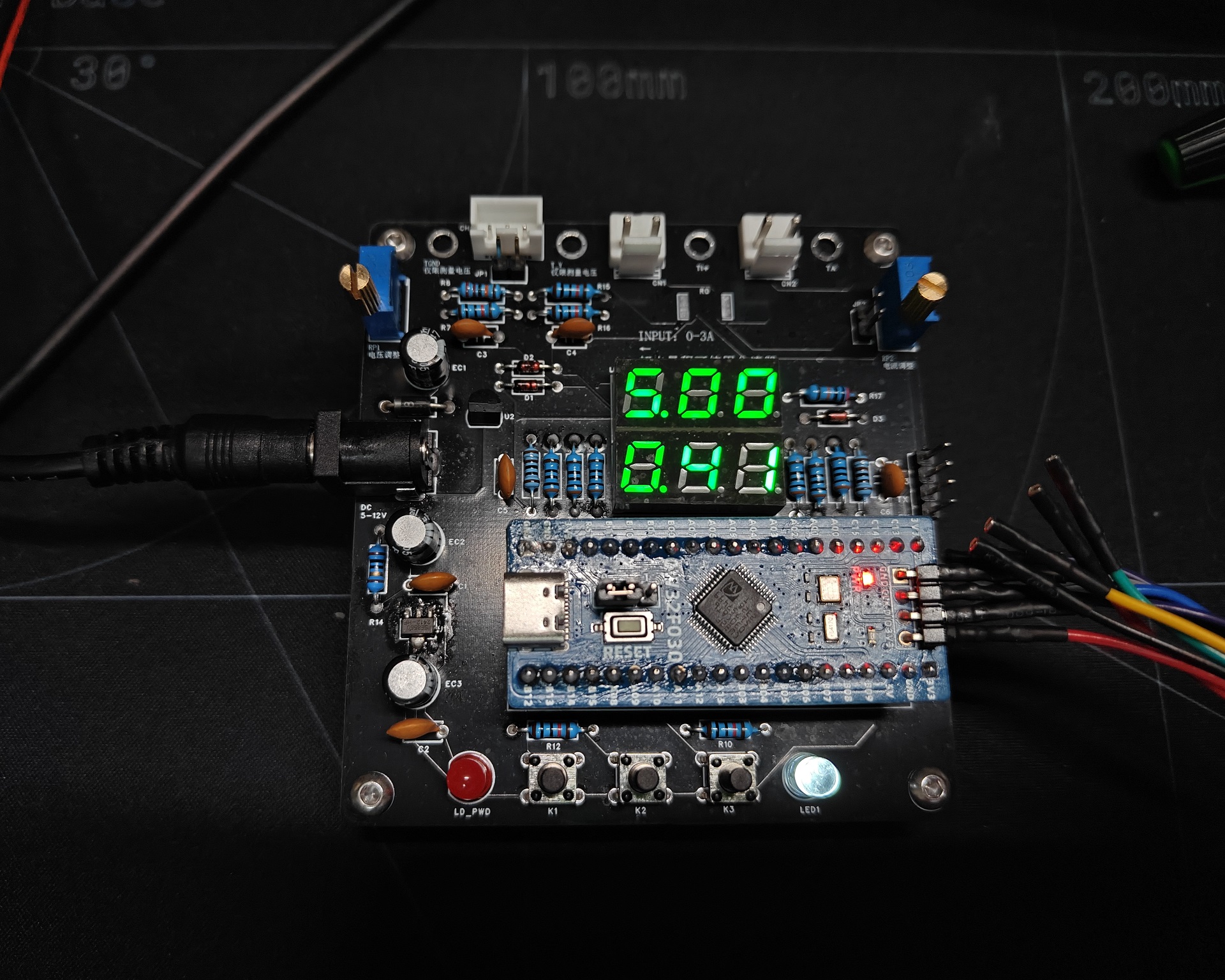
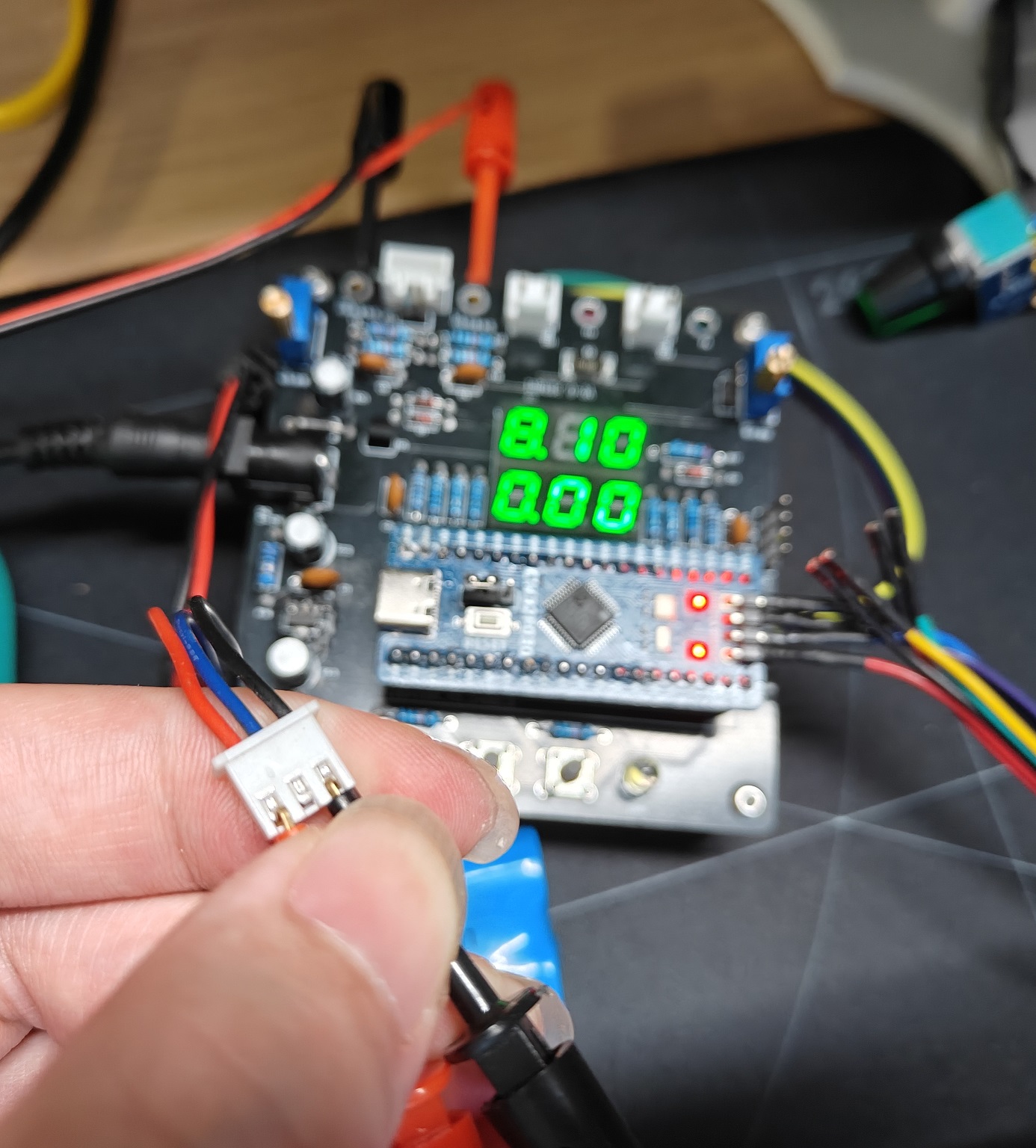
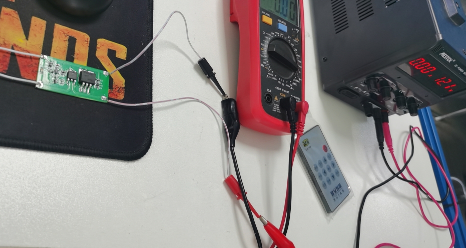
Figure 3: Verifying lithium battery voltage with a multimeter;

Figure 4: Lithium battery voltage test in this project.
BOM_Board1_PCB2_2024-08-26.xlsx
Project code.zip
PDF_CW32 Voltmeter & Ammeter - Training Camp.zip
Altium_CW32 Voltmeter & Ammeter - Training Camp.zip
PADS_CW32 Voltmeter & Ammeter - Training Camp.zip
BOM_CW32 Voltage and Ammeter - Training Camp.xlsx
92706
LM317 voltage regulator module
This voltage regulator module is based on the LM317 and features a DC 12.5V~18V input and a 12.5V 1A output.
Video Link:
LM317 Voltage Regulator Module_Bilibili_bilibili https://www.bilibili.com/video/BV14JsLekE1s/?vd_source=1c6ee17b1ef1319ab51c73e56f2935dd
Project Introduction
This project is a DC voltage regulator module designed based on the LM317, realizing a DC 12.5V~18V input and a 12.5V 1A output function. When the input voltage is higher than 12.5V, the LM317 steps down and regulates it to around 12.5V; when the input voltage is lower than 12.5V, the bypass circuit connects the input terminal.
Project Function
This design is a DC voltage regulator module based on the LM317; it automatically maintains the output terminal's voltage following and regulation function. When the input voltage is higher than 12.5V, the LM317 steps down and regulates it to around 12.5V; when the input voltage is lower than 12.5V, the bypass circuit connects the input terminal.
Project Parameters:
This design uses the LM317 as the main voltage regulator chip; a heat sink can be added if necessary.
This design uses a single-channel comparator as the voltage detection and follower chip.
The input voltage range is up to 36V, and the output voltage is 12.75V, 1A.
Principle Analysis (Hardware Description):
This project consists of the following parts: a power supply step-down section and a voltage follower section.
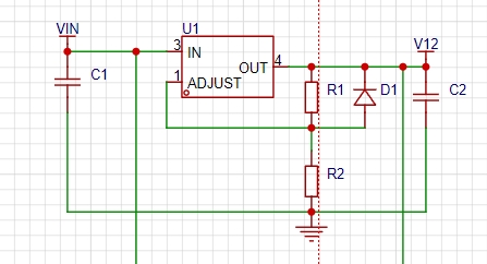
Power Supply Step-Down Circuit:
A modular design is used, with the LM317 as the main step-down chip to achieve 12.5V voltage regulation.

Voltage Follower Circuit:
A single-channel comparator is used. The output voltage value is detected by U2. When the input voltage is higher than 12.5V, the MOSFET is turned off; when the input voltage is lower than 12.5V, the MOSFET is turned on.
Software Code:
None.
Precautions:
Input and output terminals must not be reversed. Input
and output terminals must not be short-circuited.
Assembly Process:
No
physical diagram.
PDF_LM317 voltage regulator module.zip
Altium_LM317 voltage regulator module.zip
PADS_LM317 voltage regulator module.zip
BOM_LM317 voltage regulator module.xlsx
92707
electronic


 京公网安备 11010802033920号

 LPI3112A212711


