I. Hardware Design
1. Power Supply Circuit
LDO (Low Dropout Linear Regulator) Selection
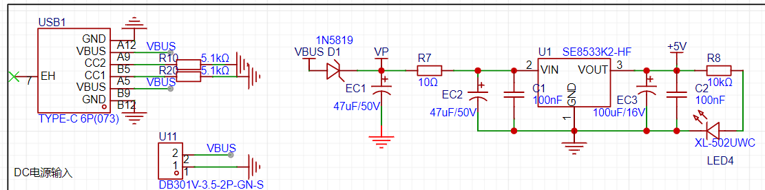
The official project uses an LDO as the power supply. Considering that most voltmeter products are used in industrial scenarios with 24V or 36V power supplies, the official project selected the SE8550K2 with a maximum input voltage of up to 40V as the power supply.
I added a Type-C interface to the official power supply circuit, which can directly supply 5V via a data cable or connect a battery via a terminal block, providing multiple power options. The remaining circuit parts are consistent with the official design.
The voltmeter power supply circuit uses a series diode for reverse connection protection, and a 10Ω resistor is connected in series for voltage division. Utilizing the principle that the 10Ω low-power resistor has low overcurrent, it acts as a low-resistance fuse, providing overcurrent protection or short-circuit protection. Because the resistor is in a heated state under overcurrent conditions, it is almost always in an open-circuit state.
Near the LDO, at the power input port, electrolytic capacitors and ceramic capacitors are connected in parallel.
The electrolytic capacitors first filter out the low-frequency part of the input voltage, providing a stable DC voltage for the circuit, which helps ensure the stability and reliability of the circuit at low frequencies.
Subsequently, ceramic capacitors further compensate for high-frequency fluctuations, filtering out high-frequency noise and pulse hazards. This high-low combination filtering method can more effectively filter out noise and fluctuations across the entire frequency band, improving the overall performance of the circuit.
Furthermore, ceramic capacitors can eliminate the inductive characteristics (parasitic inductance of capacitors) generated by electrolytic capacitors at high frequencies, further improving the filtering effect.
However, I bought the wrong LDO model, using the SE8533K2. The result was that regardless of whether the input voltage was 5V or 12V, the output voltage after passing through the SE8533K2 was only around 3.2V. This indirectly proves the voltage reduction capability of the SE8533K2 and the circuit.
Because the LCSC CW32F030C8T6 supports a wide operating voltage, a 3.2V power supply can support the normal operation of this core board.
2. MCU Selection Analysis
According to the official tutorial, the CW32 has advantages such as wide operating temperature, wide operating voltage, and strong anti-interference in this voltage and current table.
From an industrial application perspective, wide operating temperature range, wide operating voltage range, and anti-interference are all crucial selection factors, especially since this instrument is primarily used for data measurement. Cost is also a significant consideration.
However, for initial learning purposes, I believe a MCU with a certain level of ADC accuracy and a suitable clock frequency is sufficient. An external reference voltage can be used, such as the TL431 from the official tutorial. The overall project involves using an ADC to measure the input voltage by comparing the ADC's detected value with a reference voltage, and then using external circuitry to calculate the actual measured voltage and current.
3. Voltage Sampling Circuit :
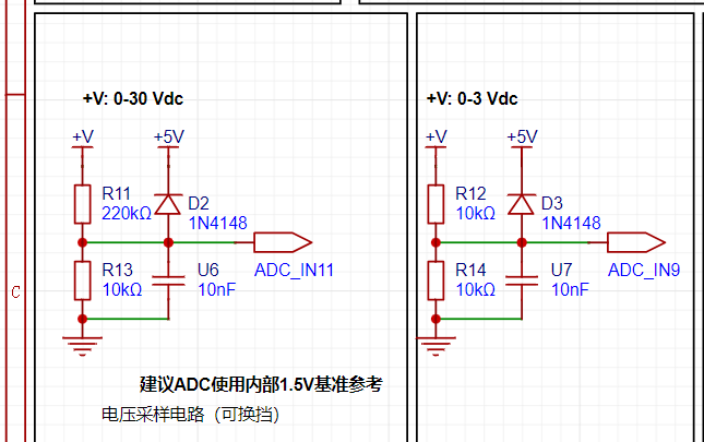
The voltage sampling circuit operates on the principle of voltage division.
Different voltage division ratios allow for the measurement of different voltages.
As shown in the diagram, by activating two different ADCs and using external voltage divider circuits with different division ratios, the range switching function of a multimeter can be initially implemented. For example, the 0-3V and 0-30V ranges shown in the diagram. If needed, different voltage division ratios and multi-range toggle switches can be experimented with, allowing for hardware selection of different ranges to mimic the range switching function of a multimeter. This training camp allows users to select different acquisition channels and display sampled values via buttons to simulate the range switching function of a multimeter.
When designing the sampling circuit, pay attention to the selection of voltage divider resistors, taking into account factors such as resistor withstand capability.


In the study of voltage sampling circuits, a voltage measurement connection port is also provided for connecting the multimeter probes to verify the accuracy of the detected voltage data.
The VP pin can power the voltmeter and ammeter, eliminating the need for the instrument's internal power supply. Only an input voltage of 3.3-30V is required. The power supply circuit described above can normally power the working module of the voltmeter and ammeter.
4. The sampling current of the current sampling circuit
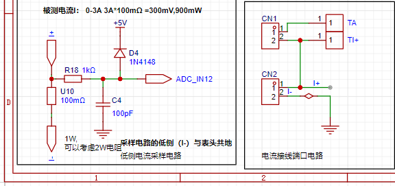
is designed for 0-3A, and the selected sampling resistor U10 is 100Ω.
It is not recommended that the voltage difference introduced by the current sensing resistor exceed 0.5V, and the power consumption should be suitable for the sensing current.
Since this project does not use an amplifier circuit, a larger sampling resistor is needed to obtain a higher measured voltage for measurement.
Considering that a larger resistor would result in a larger voltage drop and higher power consumption, an unlimited selection of a larger resistor is not feasible.
This project uses a 1W packaged resistor, corresponding to a power consumption of 1W.
Based on the above data, a 100mΩ current sensing resistor was chosen. According to the formula, 3A * 100mΩ = 300mV, 900mW.
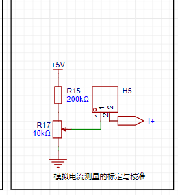
The calibration and standardization of the analog current measurement
essentially involves collecting the voltage drop across the sampling resistor when current flows through it, i.e., collecting the voltage value.
This circuit uses an adjustable resistor R17 to provide a voltage value within the range of 0-0.238V (5V/210K10K), which is then fed into the chip's current sampling pin via the I+ network.
In practical use, the voltage at I+ simulates the voltage drop across the unsoldered 100mΩ sampling resistor. At this point, the simulated measured current value
I
measured = this voltage value Vi+ / 100mΩ, which is exactly equal to the measured voltage value of 10. This provides a simulated current measurement of 0-2.38A.
Set the multimeter to the voltage measurement port. Insert the black negative probe into the T_GND interface next to the voltage measurement, and the red positive probe into the TI+ port of the current measurement to measure the actual voltage value of I+.
5. The digital tube drives
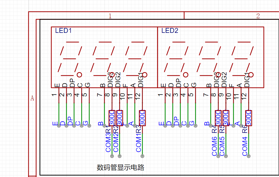
two three-digit common-cathode digital tubes. The anode is directly connected to the I/O port of the core board and driven directly through the I/O port. The cathode is connected in series with a 300Ω surface-mount resistor to the I/O port of the core board. This eliminates the need for a shift register to drive the digital tubes.
Because the TL431 was ultimately missing, it was not soldered or used.
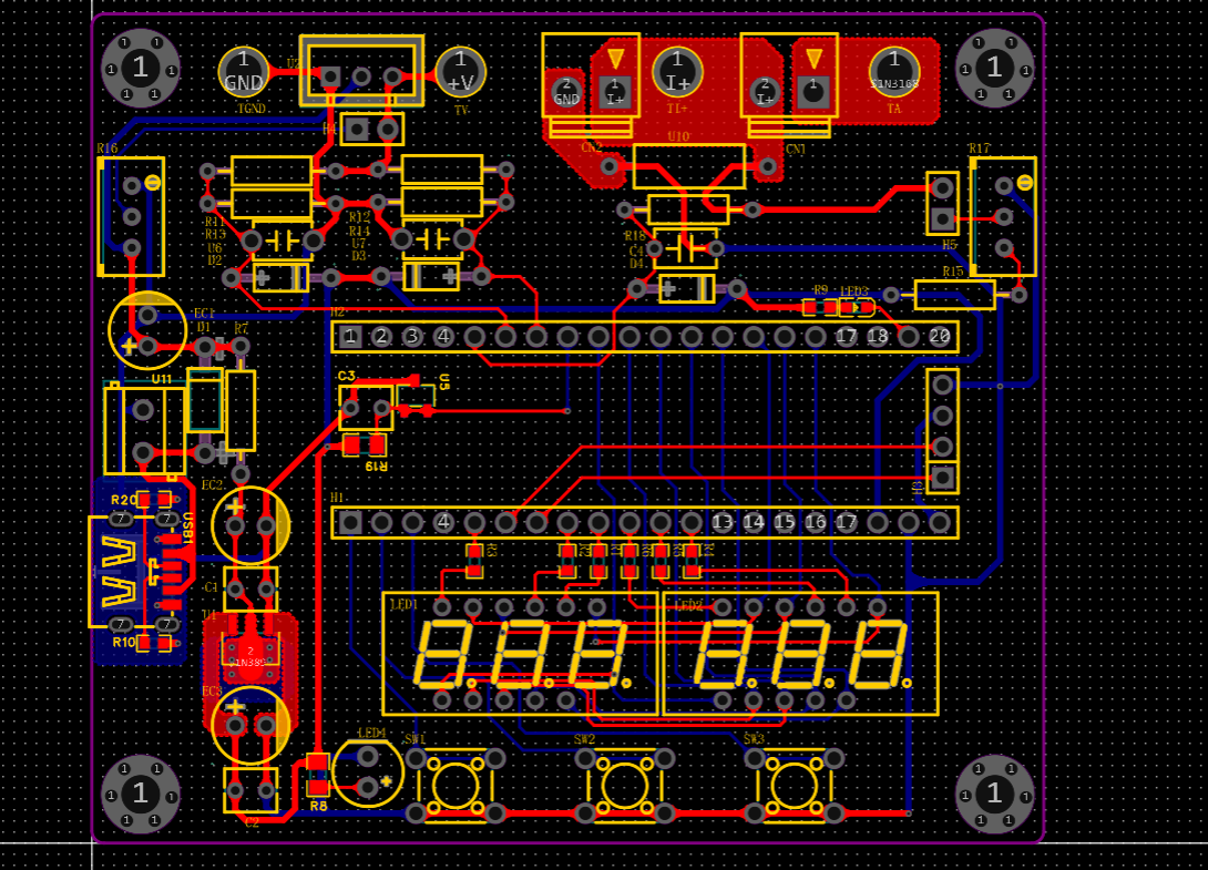
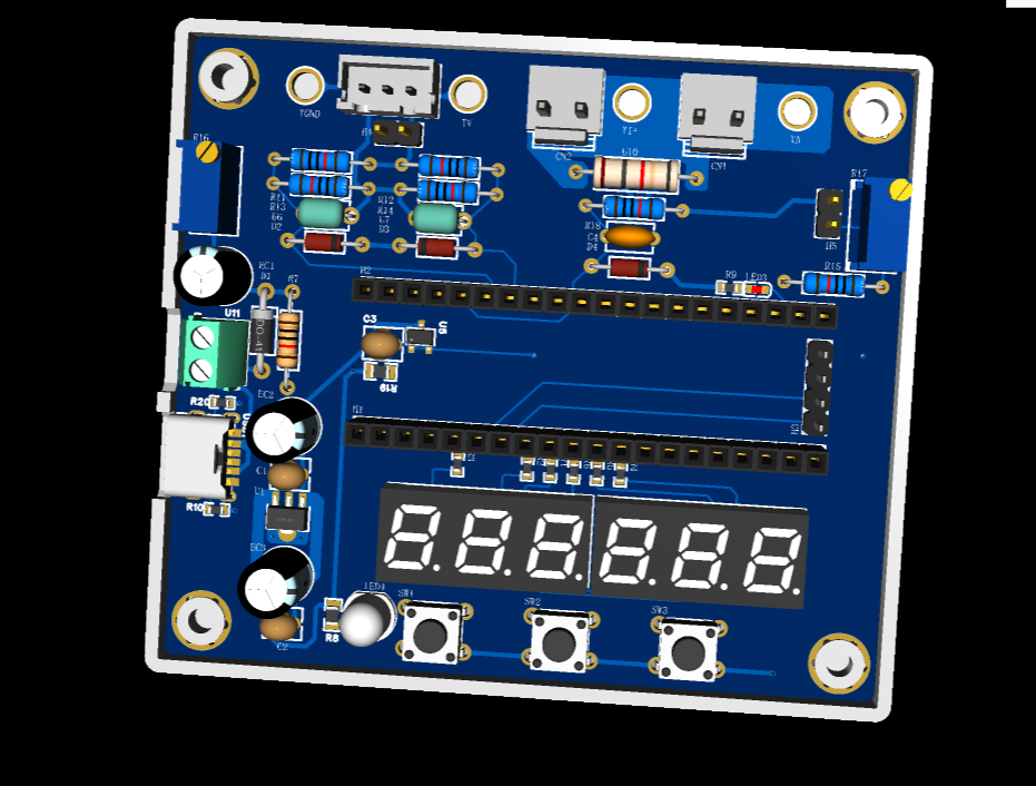
The overall PCB layout and 3D preview are as follows.
6. Software Section
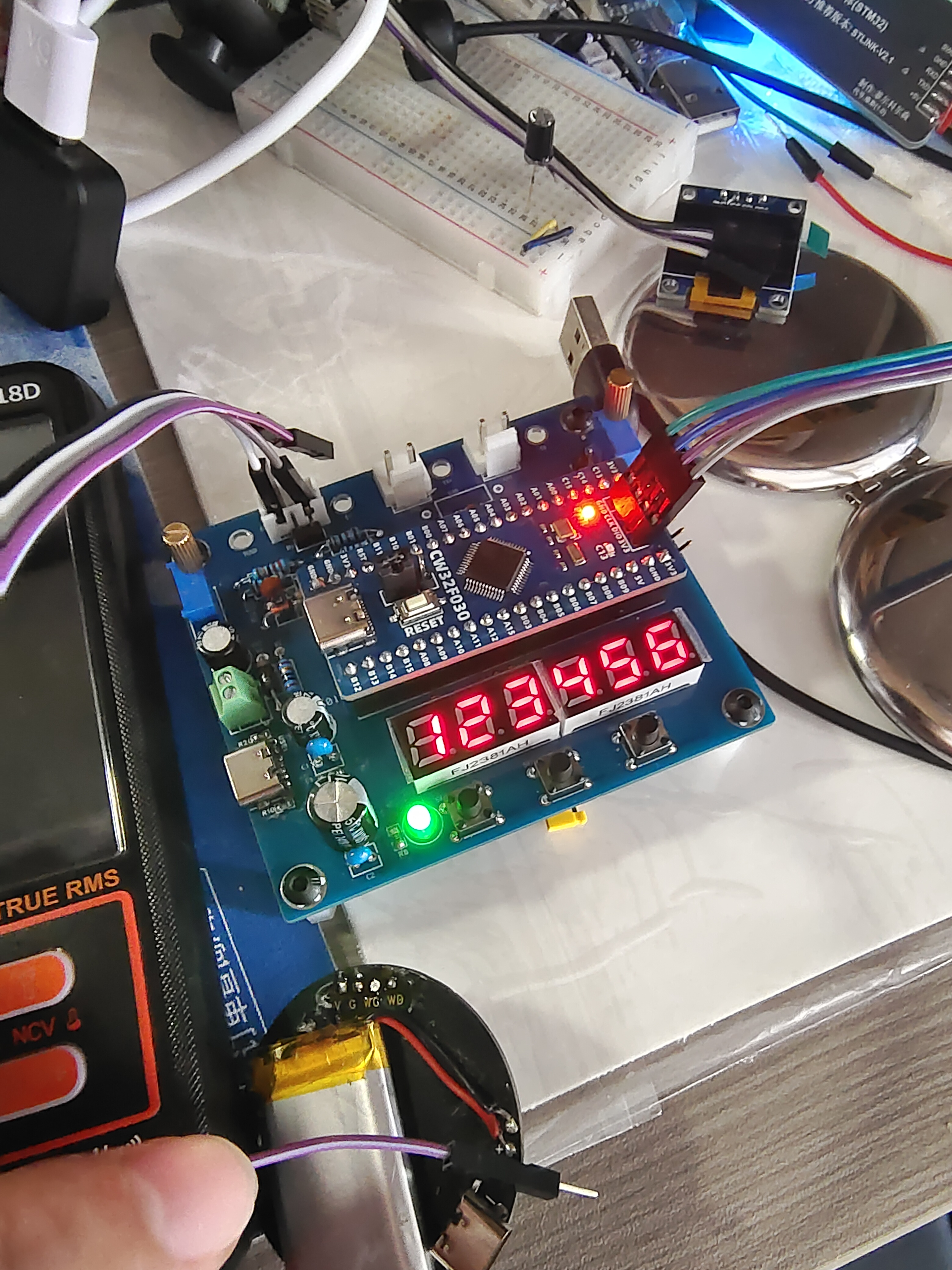
: 1. Successfully drove a six-digit LED display.
2. Verified ADC voltage detection.
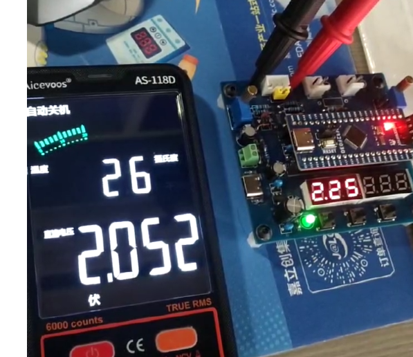
3. Verified the improvement in voltage readings after filtering.
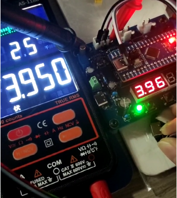
4. Verified simultaneous voltage and current sampling.

7. Summary:
This training camp taught me how to directly drive an LED display using I/O ports,
detect voltage and current via an ADC,
and learn several different filtering algorithms.
The biggest hardware takeaway was single-point grounding.
Also, it's important to consider factors like voltage, current, and power when selecting components. I also
learned how to build a safe and reliable step-down circuit.
Because my learning involved minor modifications to various example programs, I haven't fully mastered them yet. Therefore, I won't post the code.
My learning outcomes are not impressive, and I feel deeply ashamed.
Next, I will try using an external stable voltage source as a reference to implement a voltage and current meter function.


 京公网安备 11010802033920号

 2SC1310-11-G


