), using a 0.5mm 30-pin FPC to output MIPI signals, TP power, etc. It can be directly connected to the KING3399 development board or adapted for use with Taishanpai.
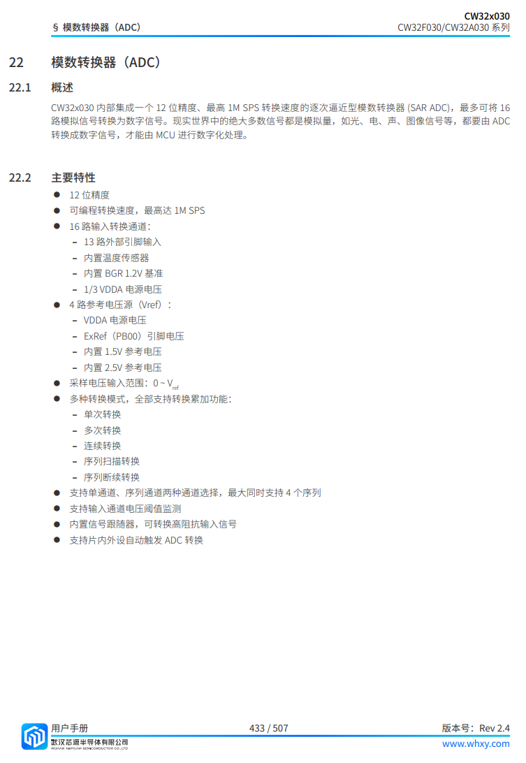
The voltage and current meter built using the CW32 microcontroller
is constructed using the "Diwenxing" core board with the CW32 microcontroller as its core. The size of the digital tube has been increased, and the original 3 digits have been changed to 4 digits.
This was my first time programming a CW32. The most advanced microcontroller I've used before was the STC32G, so the software was almost entirely copied from the training camp's example code. When I first received the code, I was worried about whether I would fail and whether I could change the 3 digits to 4 digits. Fortunately, after a few days of study, I successfully modified it. However, I don't yet fully understand some of the internal registers, so my understanding is only basic.
1. Power Supply Circuit

LDO (Low Dropout Linear Regulator) Selection:
This project uses an LDO as the power supply to avoid interference caused by DC-DC ripple. The board's power supply uses the common 7805 as the microcontroller's power supply.
2. MCU Selection Analysis:
As a DIYer, I naturally leave some margin for error when using the development chip. For ease of assembly, the core board (core board) of LCSC Diwenxing CW32F030C8Tx was chosen as the main controller. The reason for choosing CW32 is that it has a 12-bit high-speed ADC that can reach ±1.0LSB INL 11.3ENOB and multiple Vref reference voltages... (STM32 only supports VDD=Vref, CW32 is excellent in this respect!)
Of course, if we really want to make it into a product, then we can find a way to compress the code and choose a lower-spec model to reduce costs.
3. Voltage Sampling Circuit:
The voltage divider resistors in this project are designed as 220K+10K, therefore the voltage division ratio is 22:1 (ADC_IN11).
The voltage divider resistor selection
is based on the maximum measured voltage; for safety reasons, this project uses 30V (the actual maximum display value is 99.99V).
The ADC reference voltage in this project is 1.5V, which can be configured through the program.
To reduce the power consumption of the sampling circuit, the low-side resistor (R7) is usually selected as 10K based on experience.
The high-side resistance of the voltage divider resistor can then be calculated using the above parameters. The
required voltage division ratio is calculated as follows: ADC reference voltage: Design input voltage, calculated using known parameters as 1.5V/30V=0.05.
The high-side resistance is calculated as: Low-side resistance/voltage division ratio, calculated using known parameters as 10K/0.05=200K.
A standard resistor is selected: A resistor slightly higher than the calculated value is chosen; the calculated value is 200K. We usually choose E24 series resistors; therefore, in this project, 220K is selected, which is greater than 200K and closest to the calculated value.
If, in actual use, the voltage to be measured is lower than 2/3 of the module's design voltage (66V), the voltage divider resistor can be replaced and the program modified to improve measurement accuracy. The following example illustrates this:
Assuming the measured voltage is no higher than 24V and other parameters remain unchanged,
calculations show 1.5V/24V = 0.0625, 10K/0.0625 = 160K. 160K is a standard E24 resistor and can be directly selected, or a higher value 180K can be chosen with some redundancy.
If, in actual use, the voltage to be measured is higher than the module's 99V design voltage, a different resistor can be selected. To achieve a wider voltage measurement range, one can choose to replace the voltage divider resistor or modify the reference voltage. The following example illustrates this:
Assuming the measured voltage is 160V, the solution is to increase the voltage reference to expand the range.
Given that the voltage division ratio of the selected resistor is 0.0145, we can calculate 160V * 0.0145 = 2.32V using the formula. Therefore, we can choose a 2.5V voltage reference to expand the range (increasing the range will reduce accuracy).
Considering the potential fluctuations in the measured power supply, a 10nF filter capacitor is connected in parallel with the low-side voltage divider resistor to improve measurement stability.
Range switching:
In this project, an additional voltage sampling circuit was added. Therefore, we can discuss the significance of range switching for improving measurement accuracy. Multimeters often have multiple range settings for more accurate measurements. By adjusting different ranges, the optimal measurement accuracy of the measured point within the corresponding range can be obtained.
This project requires a combination of hardware and software to achieve this function. When we first use the ADC_IN11 channel mentioned earlier to measure voltages below 30V... If the measured voltage is within 0~3V, use the ADC_IN9 channel for measurement. In this case, the measurement accuracy is greatly improved due to the reduced voltage division ratio. Of course, the ADC_IN9 channel is not used in the code I provided; it will be updated in a later version.
4. Current Sampling Circuit
: This project uses a low-side current sampling circuit for current detection. When learning the common ground between the low-side of the sampling circuit and the development board's meter interface
, please do not solder R0! Do not solder R0! Do not solder R0!!! Connect the jumper, wait for the program to display normally, adjust the adjustable resistor on the right. If the current value changes, then you can solder R0.

The design analysis
for this project involves a sampling current of 3A, and the selected sampling resistor (R0) is 100mΩ.
The selection of the sampling resistor mainly needs to consider the following aspects:
the maximum value of the pre-designed measurement current;
the voltage difference caused by the 3A current sensing resistor in this project; and
the power dissipation of the current sensing resistor, which should generally not exceed 0.5V. A suitable package should be selected based on this parameter. Considering the power dissipation (temperature) issue under high current, a 1W metal wire-wound resistor package was chosen
. The voltage amplification factor across the current sensing resistor is also important. Since no operational amplifier is used to build the amplification circuit in this project, the factor is 1.
The current sensing resistor value can then be calculated using the above parameters
. Since no amplifier circuit is used, a larger sampling resistor is needed to obtain a higher measured voltage for measurement.
Considering that a larger resistor would result in a larger voltage drop and higher power consumption, an unlimited selection of a larger resistor is not feasible.
This project uses a 1W package resistor, corresponding to a power consumption of 1W.
Based on the above data, a 100mΩ current sensing resistor was selected. According to the formula, 3A * 100mΩ = 300mV, 900mW can be calculated.
To cope with different usage environments, especially high current scenarios, the R0 resistor can be replaced with constantan wire or a shunt. The choice of alternative can be made according to the actual usage scenario. For safety and educational purposes, this project will not discuss ranges exceeding 3A in detail, but the principle is the same.
5. Digital Tube Display
: The display section uses a 4-digit digital tube. The advantage of using a digital tube is high recognition, but the displayed information is limited. Of course, for voltmeters and ammeters, 8 digits are sufficient.
6. Other points to note: Due to the lack of a suitable load, I feel the calibration was not perfect, and there is room for improvement in the program. For example, the original design included two measurement ranges: 0-3V and 0-30V, which should be achievable with proper program adjustments. The TL431 voltage reference was not used in the program. (The following appears to be a list of measurements:
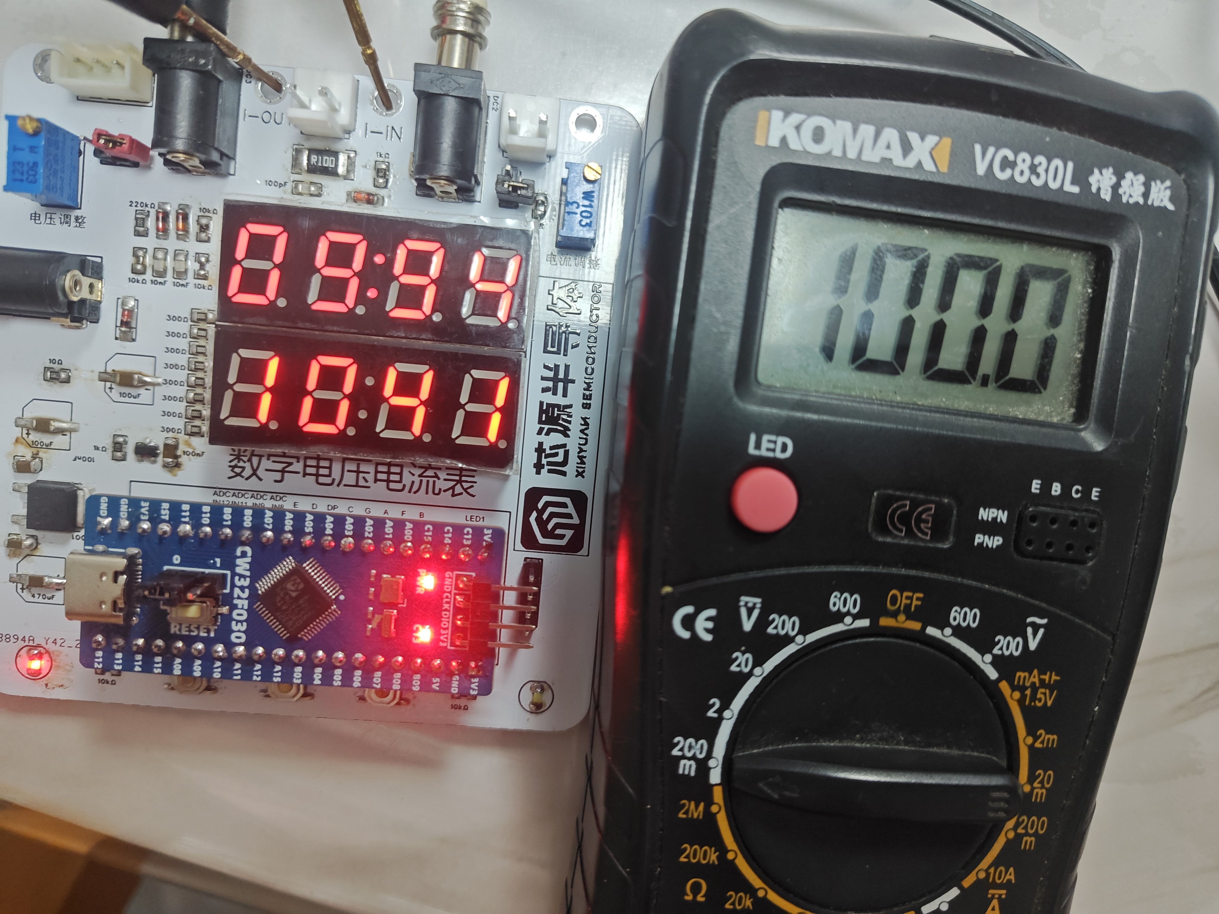
1000mA,
122mA,

17.76V,

6.57V )


 京公网安备 11010802033920号

 IDT74FST6800Q


