Introduction
This project is based on the LCSC CW32 voltmeter and ammeter training program, with both hardware and software components referencing the official solution.
The task requires
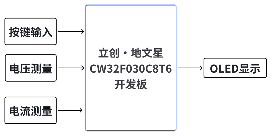
designing a voltmeter and ammeter using the LCSC CW32F030C8T6 development board to measure external voltage and current.
Analysis
The main part of this design involves the use of an ADC (Analog-to-Digital Converter). ADCs are indispensable key components in electronic systems, converting continuous analog signals into digital signals, enabling digital processing and analysis. ADCs play a crucial role in signal conversion, measurement and data acquisition, control system input, and communication and signal processing. Their widespread application promotes the intelligent and precise control of electronic equipment in various industries and is a key factor driving modern technological progress. The
digital voltmeter and ammeter combines ADC technology with circuit measurement principles, accurately converting analog voltage and current signals into digital displays for easy reading and analysis by electronic engineers. This device not only improves the accuracy and efficiency of circuit measurements but also helps engineers better understand circuit behavior, making it a powerful tool for electronic design and troubleshooting, and playing a vital supporting role in the work of electronic engineers. In product applications, digital voltmeters and ammeters ensure the accuracy and safety of circuit design, while also providing strong support for product quality control and subsequent maintenance.
Overall Design Scheme Block Diagram
Schematic Design Description
I. Power Supply Circuit
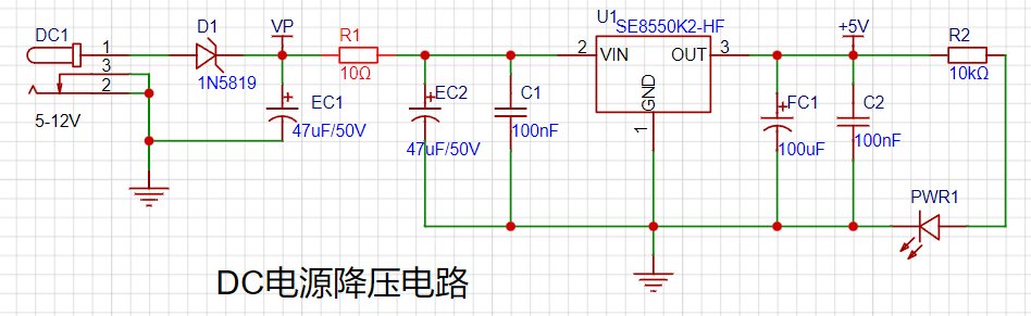
This design adopts an LDO step-down scheme. Compared to DC-DC step-down switching circuits, its advantage is that it does not involve high frequencies, and the PCB design is simpler. The power supply chip used is the SE8550K2, with a maximum input voltage of up to 40V, thus it can be used in 24V and 36V industrial scenarios.
II. Voltage Sampling Circuit
CW32 ADC Introduction
The CW32F030 integrates a 12-bit precision, 1M SPS successive approximation analog-to-digital converter (SAR ADC), which can convert up to 16 analog signals into digital signals. Most signals in the real world are analog quantities, such as light, electricity, sound, and image signals, which must be converted into digital signals by an ADC before being digitized by the MCU.
The main focus is on the CW32's four reference voltage sources (Vref),
VDD (power supply voltage),
ExRef (PB04) pin
voltage (built-in 1.5V
reference voltage), and a built-in 2.5V

reference voltage. The resistor divider design broadens the measurable voltage range.
If 1.5V is used as the reference voltage, based on the resistance ratio of R8 and R7, the highest sampling voltage can be obtained as: 1.5 / 10 * (220 + 10) = 34.5V.
The voltage calculation formula
(ADC sampling value / 4096) is: 1.5 * (220 + 10) / 10 = Actual value.
From the voltage calculation formula, it can be seen that the ADC measurement accuracy is highest at a 1.5V reference voltage. Compared to other 32-bit microcontrollers, the CW32's ADC performance is clearly better.
III. Current Sampling Circuit:
This project uses a low-side current sampling circuit for current detection. When learning how to use the low-side sampling circuit and the development board's meter interface
, please do not solder R0!

The design analysis
for this project involves a sampling current of 3A, and the selected sampling resistor (R0) is 100mΩ.
The selection of the sampling resistor mainly needs to consider the following aspects:
the maximum value of the pre-designed measurement current;
the voltage difference caused by the 3A current sensing resistor in this project; and
the power dissipation of the current sensing resistor, which should generally not exceed 0.5V. A suitable package should be selected based on this parameter. Considering the power dissipation (temperature) issue under high current, a 1W metal wire-wound resistor package was chosen
. The voltage amplification factor across the current sensing resistor is also important. Since no operational amplifier is used to build the amplification circuit in this project, the factor is 1.
The current sensing resistor value can then be calculated using the above parameters
. Since no amplifier circuit is used, a larger sampling resistor is needed to obtain a higher measured voltage for measurement.
Considering that a larger resistor will result in a larger voltage drop and higher power consumption, an unlimited selection of a larger resistor is not feasible.
This project uses a 1W package resistor, corresponding to a power consumption of 1W.
Based on the above data, a 100mΩ current sensing resistor was selected. According to the formula, 3A * 100mΩ = 300mV, 900mW can be calculated.
To cope with different usage environments, especially high current scenarios, the R0 resistor can be replaced with constantan wire or a shunt. The choice of alternative can be made according to the actual usage scenario. For safety and educational purposes, this project will not discuss measurements exceeding 3A, but the principle is the same. IV. OLED Display Circuit
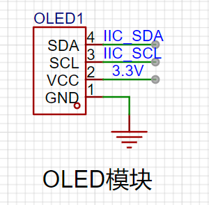
Communication Interface: IIC is selected. Only two pins are needed for communication of display data. Since the OLED module used has a built-in pull-up resistor, it can be directly connected to the microcontroller's I/O port.
V. LED Indicator:
This project additionally designed a power indicator and an I/O operation indicator.
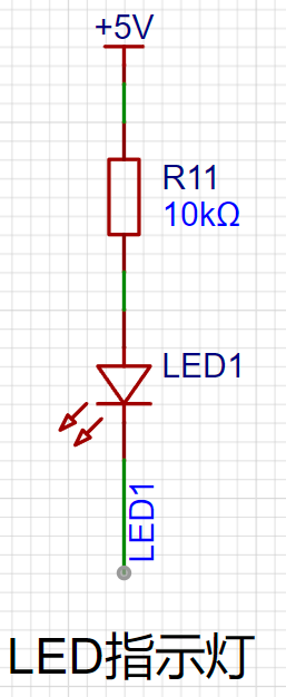

PWR1 is a power indicator light, and R2 and R11 are current-limiting resistors.
VI. Button Circuit Design

: Configure the I/O ports connected to K1, K2, and K3 as pull-up pins
(default high level). When a button is pressed, check if the corresponding I/O port is low to obtain the currently pressed button number. VII. TL431 Circuit Design for Voltage Measurement Calibration (Not Used):
This project adds an extra TL431 circuit to provide a 2.5V reference voltage. This can be used to provide an external voltage reference for calibrating the AD converter. From a product design perspective, due to the inherent ADC performance advantages of the CW32, this circuit is unnecessary. This circuit was designed on the development board to learn the relevant application principles.
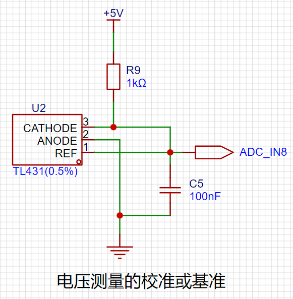
The TL431 is a relatively "old" device, very classic, and widely used; it is still found in many electronic products.
Many beginners may be encountering this device for the first time, so we will briefly explain the principles of this product to help everyone better apply the TL431.
TI defines it as a precision programmable reference. On the first page of the references, we can focus on several key characteristics.
Precision: Precision indicates that its output voltage is very accurate. I used a TL431 with ±0.5% accuracy, which measured 2.495V on the board at room temperature. Compared to common Zener diodes, the accuracy is vastly different. In the application circuit diagram, the TL431 is represented by a Zener diode symbol.
Adjustable Output Voltage: The adjustable output voltage is between Vref and 36V. In our project, we use the output Vref voltage, which is approximately 2.5V. Therefore, we use 2.5V in the description, which is approximately equal to 2.5V in reality.
Sinking Current Capability: This refers to how much current the output voltage pin can provide, which is greatly related to the resistance value (R13) in the application circuit. It should not be less than 1mA. If there is no need for sinking current, do not design the current to be too high, causing unnecessary power consumption.
Software Description
Engineering Structure

Key logic processing function
void Key_Scan(void) //Key scanning
{
if(GPIO_ReadPin(CW_GPIOB,GPIO_PIN_3) == GPIO_Pin_RESET) //Check if PB3 is low
{
Flag1_Key = 1;
}
if(Flag1_Key) //Then check the flag bit
{
if(GPIO_ReadPin(CW_GPIOB,GPIO_PIN_3) == GPIO_Pin_SET) //If the key has been released
{
Flag1_Key = 0; //Clear the flag bit, wait for the next key detection
mode++;
OLED_CLS(); //Clear the screen every time the interface is switched
if(mode>=5) mode=0;
}
}
if(GPIO_ReadPin(CW_GPIOB,GPIO_PIN_4) == GPIO_Pin_RESET) //Check if PB4 is low
{
Flag2_Key = 1;
}
if(Flag2_Key) //Then check the flag bit
{
if(GPIO_ReadPin(CW_GPIOB,GPIO_PIN_4) == GPIO_Pin_SET) // If the button has been released
{
Flag2_Key = 0; // Clear the flag and wait for the next button detection
if(mode==1) // Calibrate to 5V
{
X05=Mean_Value_Filter(Volt_Buffer,ADC_SAMPLE_SIZE);
save_calibration();ComputeK();Volt_Cal();mode=0;
}
if(mode==2) // Calibrate to 15V
{
X15=Mean_Value_Filter(Volt_Buffer,ADC_SAMPLE_SIZE);
save_calibration();ComputeK();Volt_Cal();mode=0;
}
if(mode==3) // Calibrate to 0.5A
{
IX05=Mean_Value_Filter(Curr_Buffer,ADC_SAMPLE_SIZE);
save_calibration();ComputeK();Volt_Cal();mode=0;
}
if(mode==4) //calibrate to 1.5a
{
IX15=Mean_Value_Filter(Curr_Buffer,ADC_SAMPLE_SIZE);
save_calibration();ComputeK();Volt_Cal();mode=0;
}
}
}
if(GPIO_ReadPin(CW_GPIOB,GPIO_PIN_5) == GPIO_Pin_RESET) //check if PB5 is low
{
Flag3_Key = 1;
}
if(Flag3_Key) //then check the flag
{
if(GPIO_ReadPin(CW_GPIOB,GPIO_PIN_5) == GPIO_Pin_SET)//if the button has been released
{
Flag3_Key = 0; //clear the flag, wait for the next button detection
mode = 0; //switch mode
}
} Five operating modes are defined. The SW1 key is used to switch display modes. The SW2 key sets the parameter value for the corresponding mode and saves it to FLASH. The SW3 key returns to mode 0.
Mode 0: Displays normal voltage and current values (the upper row of the digital tube displays the voltage value in .V or .V automatically, the lower row displays the current value in _.**A). Mode 1: 5V voltage calibration setting. The upper row of the digital tube displays 5.05. The lower row displays the current voltage value in _.V or ._V. In this mode, the multimeter should be set to 5.00V to measure the measured bit. Pressing the K2 key calibrates the current value to 5V. Mode 2: 15V voltage calibration setting. The upper row of the digital tube displays 5.15. The lower row displays the current voltage value in _.V or ._V. In this mode, the multimeter should be set to 15.0V to measure the measured bit. Pressing the K2 key calibrates the current value to 15V.
Mode 3: 0.5A Current Calibration Setting. The top row of the digital display shows A.0.5. The bottom row shows the current value _.**A. Pressing the K2 key sets the current value to 0.5A.
Mode 4: 1.5A Current Calibration Setting. The top row of the digital display shows A.1.5. The bottom row shows the current value *.**A. Pressing the K2 key sets the current value to 1.5A.
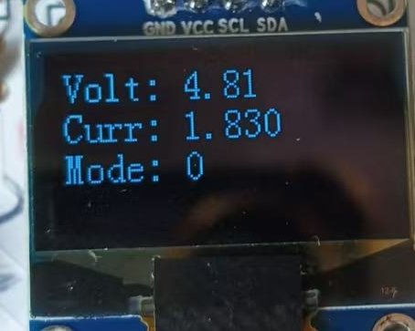
The OLED interface displays the following functions:
`void oled_show(void)
{
if(mode == 0) //Mode 0: Displays the currently measured voltage, current, and current mode in sequence
{
volt_show = (float)volt;//Convert to floating-point
volt_show = volt_show/100; //Divide by 100 for the actual voltage value
sprintf(volt_value, "Volt: %0.2f",volt_show);//Display two decimal places
OLED_ShowStr(0, 0 ,(unsigned char *)volt_value,2);
curr_show = (float)curr;
curr_show = curr_show/100; //Divide by 100 for the actual current value
sprintf(curr_value, "Curr: %0.3f",curr_show);//Display three decimal places
OLED_ShowStr(0, 2 ,(unsigned char *)curr_value,2);
sprintf(mode_value, "Mode: %d",mode);
OLED_ShowStr(0, 4 ,(unsigned char *)mode_value,2);
}
。 。 。 。 。 。 。
}
The display effect is shown in the figure:
Note:
Polarized capacitors EC1, EC2, and FC1 must not be soldered in reverse. Pay attention to the polarity when soldering diodes as well.
Summary:
Thank you for this training camp; I learned a lot of new knowledge.


 京公网安备 11010802033920号

 HBSTC-117-S-XXX-28-H-200-LT


