1. Design Purpose:
To control the water tank level in a relatively simple way.
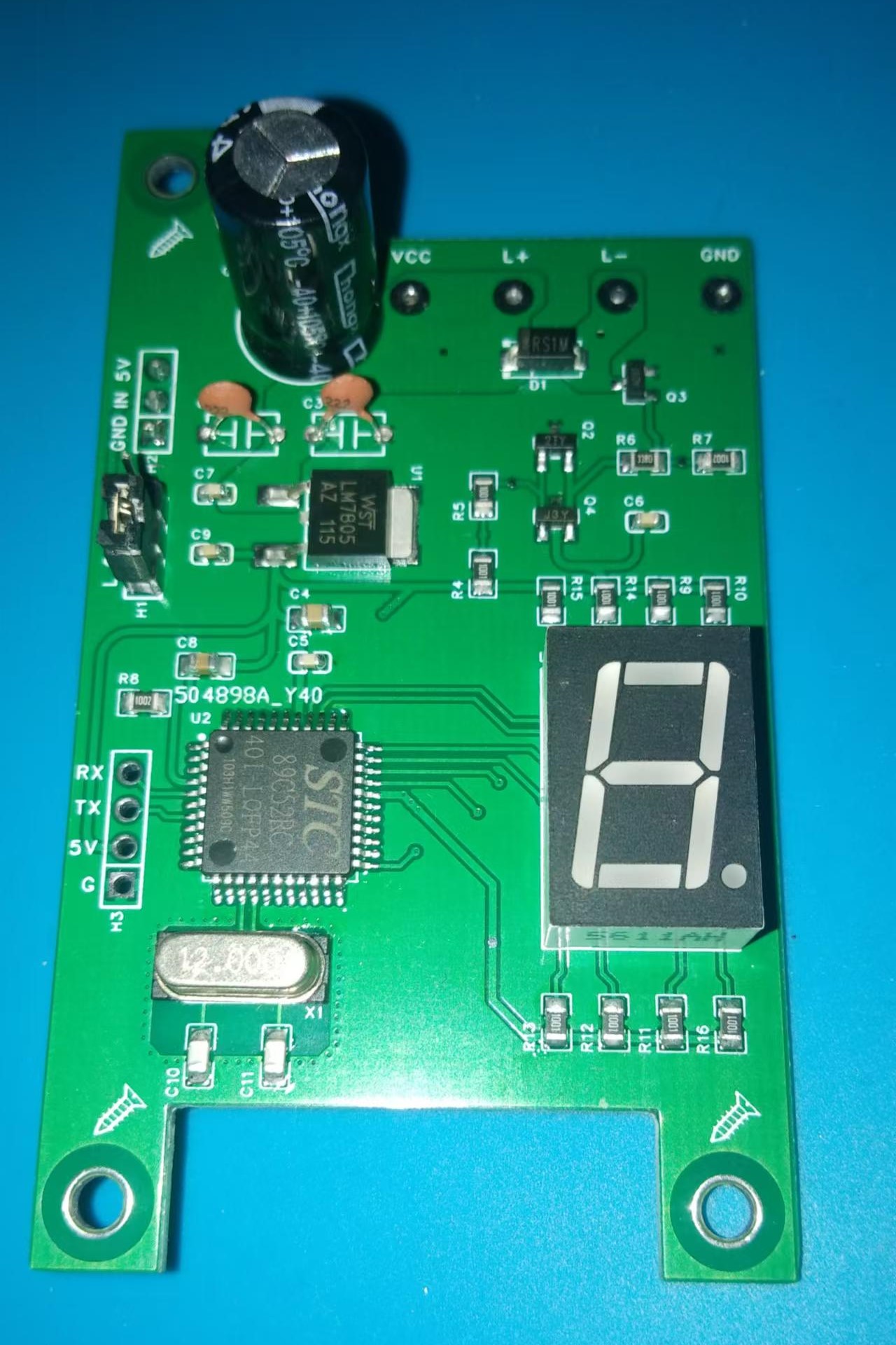
2. Electrical Characteristics
: Input Voltage: 8~35V DC (limited by 7805)
3. Workflow:
After the system is powered on, it immediately initializes all I/O ports and waits for a period of time until the system stabilizes. Then, it immediately executes the digital tube test function to facilitate visual inspection of the digital tube for damage.
After the check program completes, the system enters the normal working process. In the timer interrupt function, the microcontroller reads the float switch once every certain period of time (based on timers TL and TH) to determine whether the water level has dropped.
If no water level drop is detected, the digital display shows a standby animation. If a water level drop is detected, the digital display will show a countdown of approximately 6 seconds (actually starting from the 5th second) before rechecking the water level to prevent malfunctions caused by water surface fluctuations or external interference. During this time, the float switch will continue to be read. If no water level drop is detected, the system returns to the standby screen and starts a new round of checks. If a water level drop is still detected after 6 seconds, the system is considered to be in a valid state, and the microcontroller executes the water filling action. Current can flow between L+ and L- under the control of the MOSFET, energizing the normally closed solenoid valve (or other actuator) connected to it, and water begins to be filled into the tank. The digital display shows a water filling animation.
After the water filling action is executed, the system records the water filling time. Before the water filling time reaches the upper limit (approximately 330 seconds), the float switch detects that the tank is full, performs approximately 1 second of de-shaking, and then checks again. If the tank is found to be full, water filling stops immediately, the digital display returns to the standby screen, and the system enters a new cycle. If the float switch does not detect a full water level before the water filling time reaches its maximum (approximately 330 seconds), the float switch is considered faulty, the system immediately stops water filling, and an "Err" error message is displayed on the digital tube. To prevent a complete water overflow, once the system enters the error state, it will only resume normal operation after the microcontroller is reset.
4. Precautions:
1. Please refer to the schematic diagram for component identification; do not use the system-generated BOM
. 2. When soldering power supplies, pay close attention to polarity.
3. Take precautions against water damage in actual applications
. 4. I am not a professional programmer; feedback on any bugs encountered during use is welcome.


 京公网安备 11010802033920号

 C052T102K1BX5CM


