 2.1 The main control circuit
 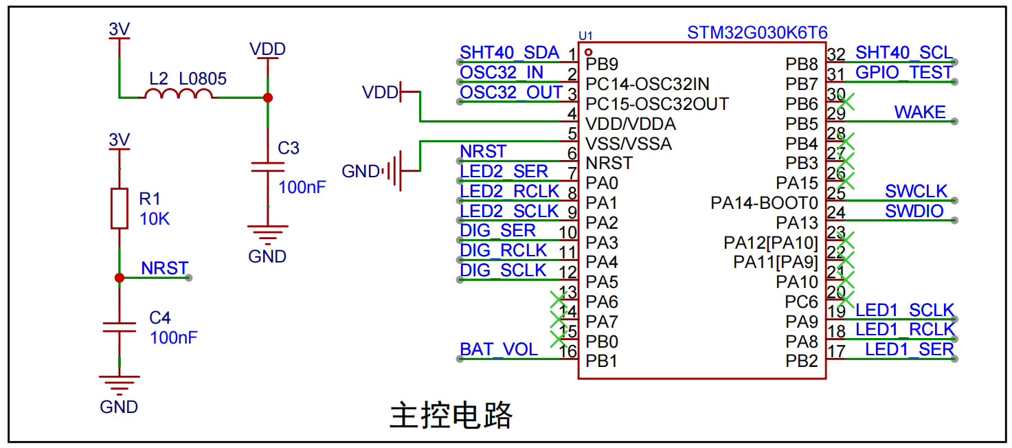 uses ferrite beads and capacitors for filtering to improve the power supply stability of the main control chip. A power-on reset circuit is included, but a manual reset circuit is not included.
  uses an external 32.768kHz passive crystal oscillator, reserved for future expansion functions; this project uses an internal crystal oscillator.
  This project uses the Sensirion SHT40 temperature and humidity sensor, which features high accuracy and low power consumption. The SHT40 itself is very small and difficult for beginners to solder. This training camp project provides an SHT40 module; simply solder a 4-pin socket onto the board, plug in the SHT40 module, and it's ready to use—very convenient.
 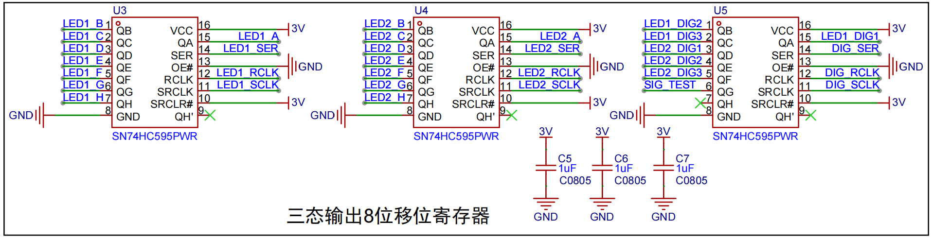 uses three 595 shift registers to control two digital tubes displaying values. This allows multiple digital tubes to be controlled with only a few main control chip I/O ports. Here, LED1X controls the first digital tube display, LED2X controls the second, and LEDX_DIG controls the common-polarity side of the digital tube.
  The LED test circuit is a test circuit to verify whether the board can work properly after soldering. After the board is soldered, the LEDs can be turned on and off by controlling the level change of the FPIO_TEST pin through the LED lighting program. If the LEDs can be turned on and off normally, it means that your hardware circuit is basically fine (but not completely fine), and the software environment is also basically successfully set up.
 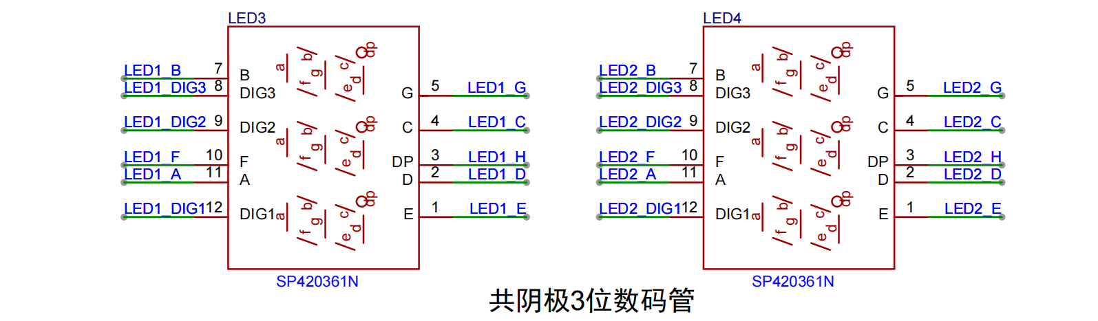 Two 3-digit LED displays show temperature and humidity values respectively. The two displays are directly controlled by three 595 shift registers, which in turn are controlled by an STM32G0 main control chip. The schematic
  Furthermore, the software design code differs when using a common anode LED display; refer to the software section for details.
 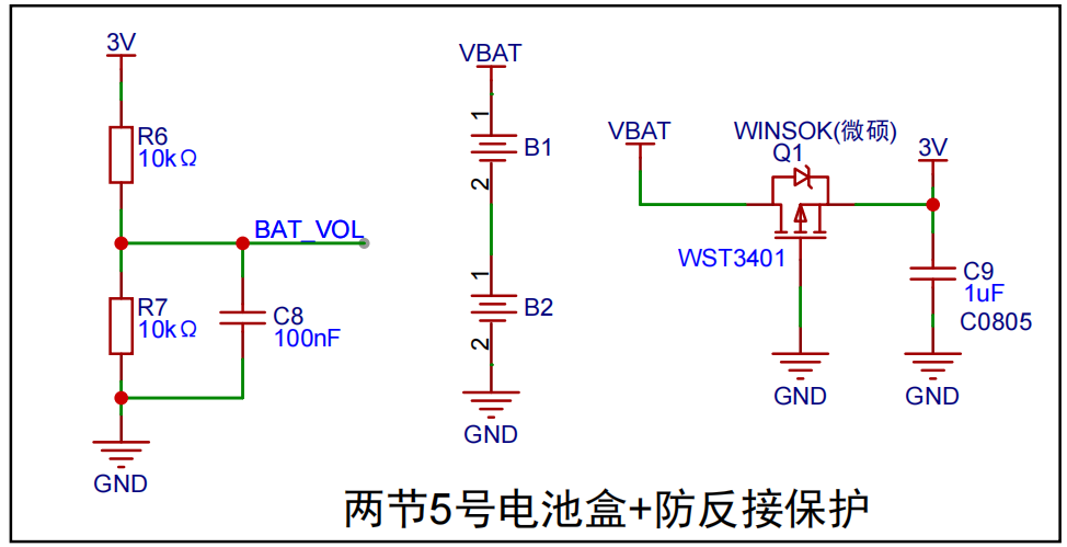 : The temperature and humidity detector uses two AA batteries, and the battery voltage can be detected by the main control chip.
  Used for downloading and debugging programs.
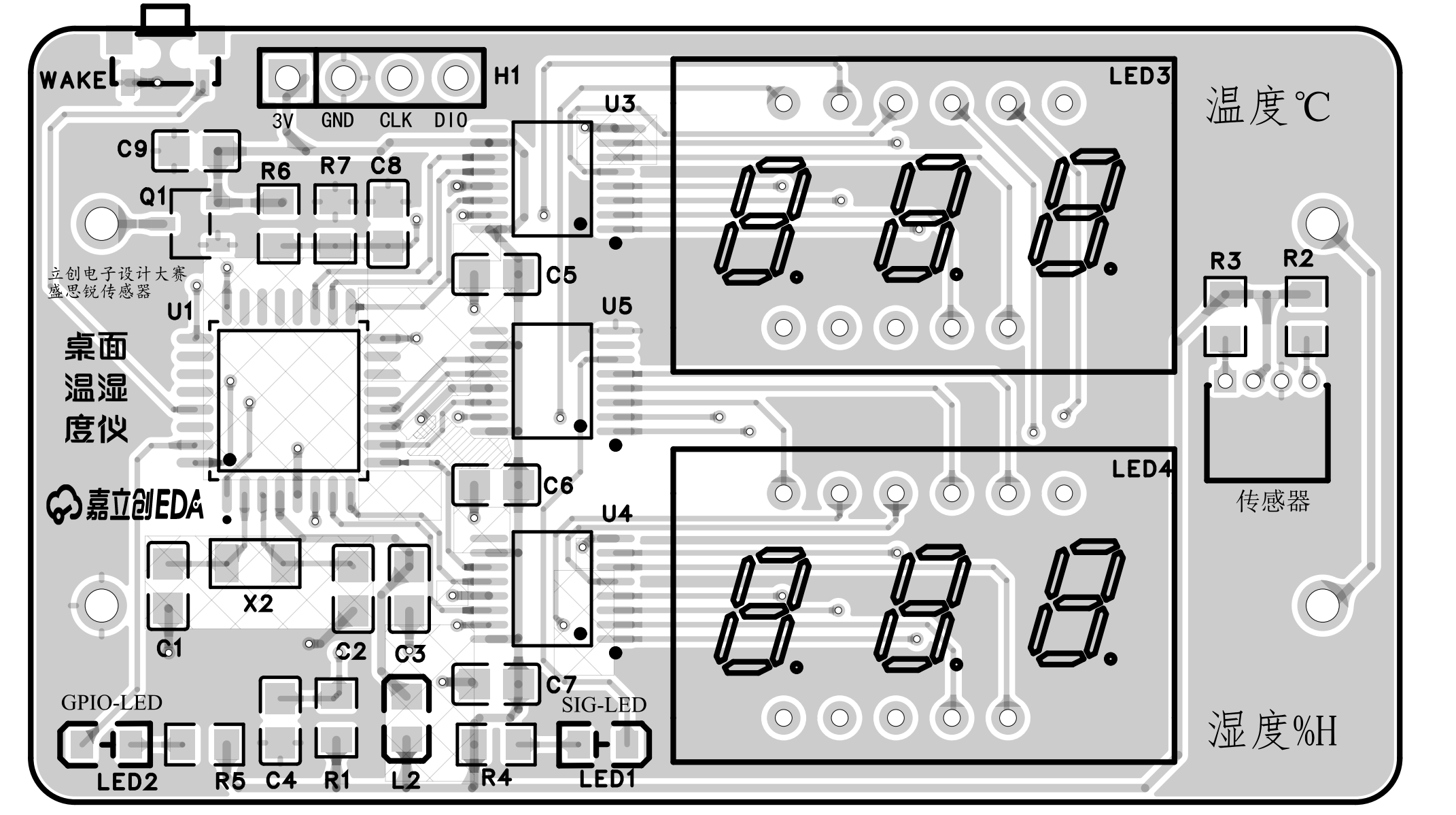
 3.2 3D View
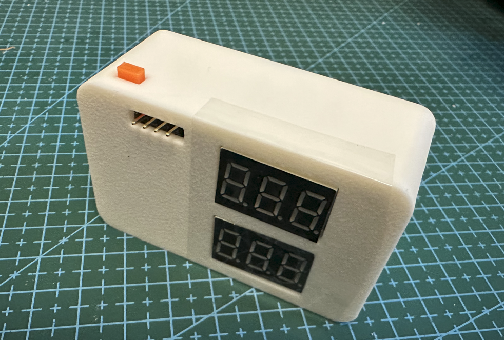
 3.3 Completed Soldering Sample Image
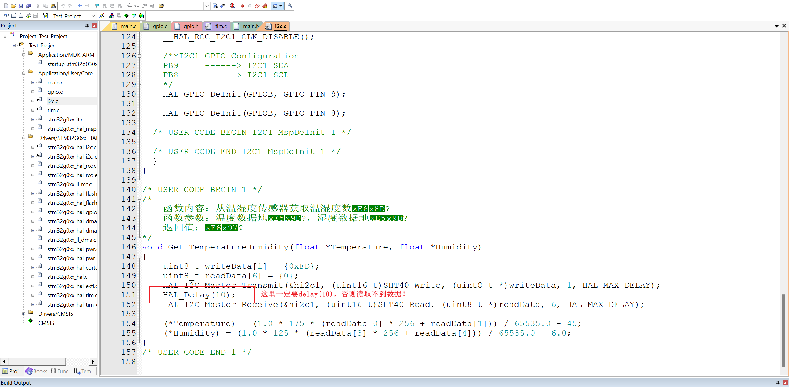
  * 4. Software Part
  The code is developed using Keil5. Pay special attention to the displayed values and hexadecimal decimal points on the common anode seven-segment display.
 For program burning, ST-Link is used. Make sure to check if your ST-Link is working properly. I couldn't burn the program the first time I used a faulty ST-Link; I had to buy a new one before I could successfully burn the program.

 *6, BOM list
 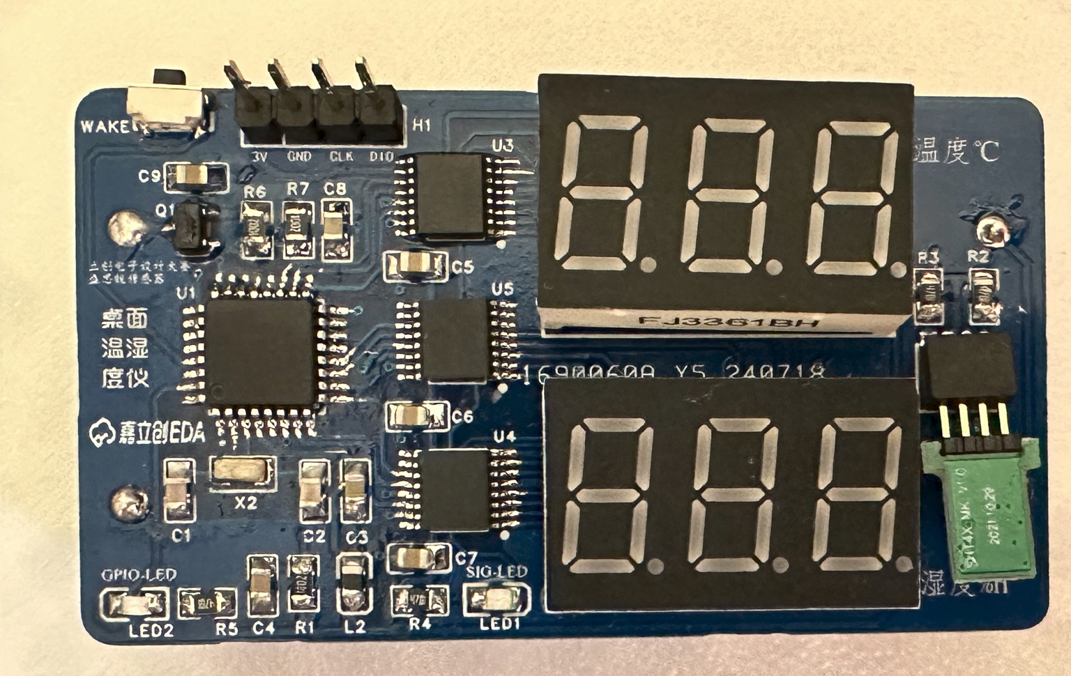 JLCPCB EDA logo and Sensirion sensor text label printed on the physical object.
All reference designs on this site are sourced from major semiconductor manufacturers or collected online for learning and research. The copyright belongs to the semiconductor manufacturer or the original author. If you believe that the reference design of this site infringes upon your relevant rights and interests, please send us a rights notice. As a neutral platform service provider, we will take measures to delete the relevant content in accordance with relevant laws after receiving the relevant notice from the rights holder. Please send relevant notifications to email: bbs_service@eeworld.com.cn.
It is your responsibility to test the circuit yourself and determine its suitability for you. EEWorld will not be liable for direct, indirect, special, incidental, consequential or punitive damages arising from any cause or anything connected to any reference design used.
Supported by EEWorld Datasheet
EEWorld
subscription
account

EEWorld
service
account

Automotive
development
community

Robot
development
community

About Us Customer Service Contact Information Datasheet Sitemap LatestNews


Room 1530, 15th Floor, Building B,
No.18 Zhongguancun Street,
Haidian District,
Beijing, Postal Code: 100190
China
Telephone: 008610 8235 0740
 京公网安备 11010802033920号

 P6KE24CA


