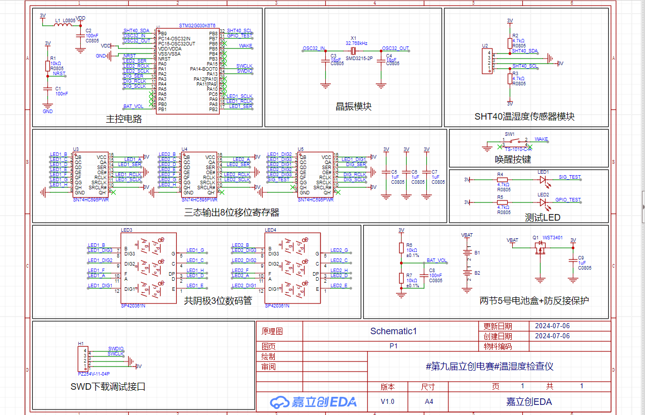
1. Schematic Diagram:
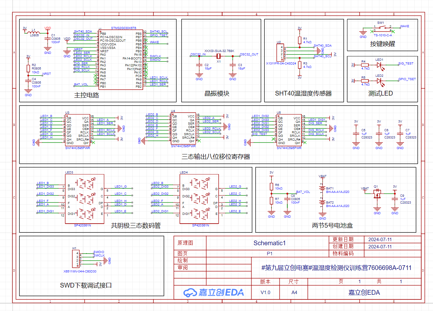
The temperature and humidity detector mainly uses an STM32G030K6T6 as the main control chip, an SHT40 as the temperature and humidity sensor, and an eight-bit shift register with tri-state outputs to control a tri-state digital tube for display. It is powered by 3V.
2. PCB Layout:

Project.7z
ProProject_#9th LCSC Electronics Design Contest# Temperature and Humidity Detector Training Camp 7606698A-0711_2024-07-30.epro
BOM_Board1_Schematic1_2024-07-30.xlsx
PDF_#9th LCSC Electronics Design Contest# Temperature and Humidity Detector Training Camp 7606698A-0711.zip
Altium_#9th LCSC Electronics Design Contest# Temperature and Humidity Detector Training Camp 7606698A-0711.zip
PADS_#9th LCSC Electronics Design Contest# Temperature and Humidity Detector Training Camp 7606698A-0711.zip
BOM_#9th LCSC Electronics Design Contest# Temperature and Humidity Meter Training Camp 7606698A-0711.xlsx
93362
#8th LCSC Electronics Contest# Renesas RA Balance Bike
1. Balance car operation modes (controlled via Bluetooth): (1) Balance mode (2) Follow mode (3) Obstacle avoidance mode.
2. Mobile phone control of the car's forward, backward, turning, acceleration, deceleration, etc.
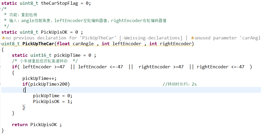
3. Car pick-up and put-down detection (controlling whether the car is running)
, etc.
1. Project Function Introduction
1. Balanced Car Operation Modes (Controlled via Bluetooth): (1) Balanced Mode (2) Follow Mode (3) Obstacle Avoidance Mode. 2. Mobile phone controls the car to move forward, backward, turn, accelerate, decelerate, etc. 3. Car pick-up and put-down detection (controls whether the car is running) 4. Can be debugged with the host computer via Type-C data cable 5. Reserved NRF24L01, infrared interface, and multi-channel power interface for expansion development
2. Project Showcase

3. Introduction

2 strings of batteries generate 7.2V, input to the power module to generate 5V, and then generate 3.3V through LDO.
Balanced Mode: The car's attitude is detected by MPU6050, and the RA MCU controls the motor drive module to control the motor to run and display it on the OLED.
Follow Mode: The car detects the distance through the ultrasonic module and starts tracking within a certain distance.
Obstacle Avoidance Mode: The car goes straight and judges whether there is an obstacle in front through the ultrasonic module. If an obstacle is encountered, it will turn.
Bluetooth: The mobile phone controls the car's operation mode by connecting to the Bluetooth module and can control the car.
4. Hardware Components:

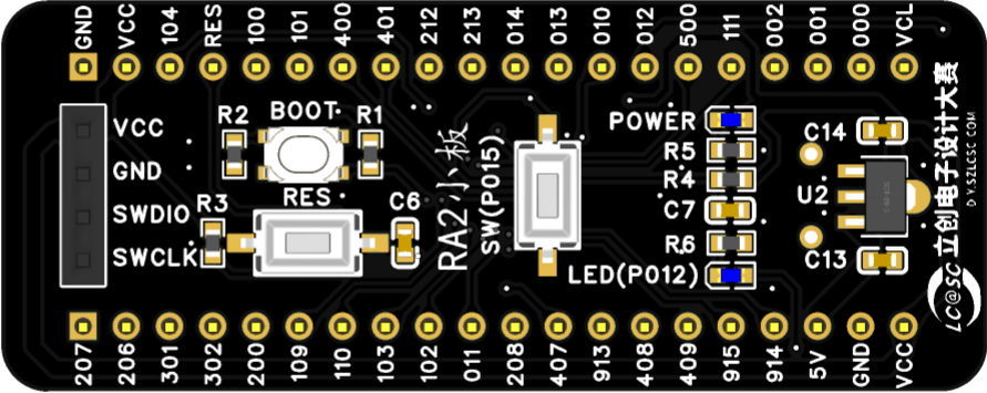
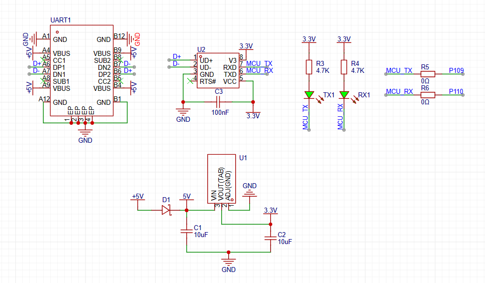
RA2 Small Board Schematic Diagram; Balance
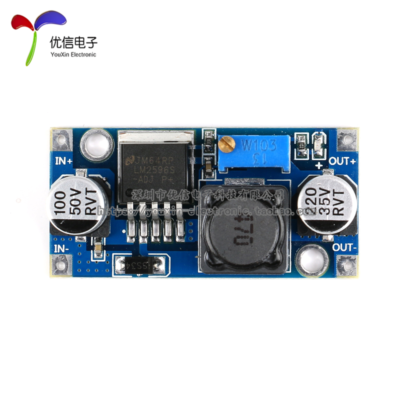
Cart Base Board Onboard Serial Port Module and LDO; Power Supply Module: LM2596S DC-DC Step-Down Power Supply Module; OLED Module: 0.96-inch OLED Display LCD Screen Module ; Bluetooth Module: Bluetooth 3.0 Module; SPP Transparent Transmission Compatible with HC-05/06 Slave JDY-31 ; MPU6050 Module: MPU-6050 Module; Three-Axis Accelerometer + Three-Axis Gyroscope; Motor Driver Module: TB6612FNG Motor Driver Module. 5. Software Components: Balance Cart Fall Detection: When the cart falls (reaches a certain angle), the motor stops. Balance Cart Pickup Detection: When the cart is picked up (wheels rotate at high speed for a certain time), the motor stops. Balance Car Putting Down Detection: When the cart is put down again for a certain time (wheels do not rotate and the angle is less than a certain range), it re-enters the balancing mode . Resources Used:


Renesas RA Bluetooth Balance Scooter.mp4
RA2E1_Car.zip
PDF_#8th LCSC Electronics Contest# Renesas RA Balance Bike.zip
Altium_#8th LCSC Electronics Contest# Renesas RA Balance Bike.zip
PADS_#8th LCSC Electronics Contest# Renesas RA Balance Bike.zip
BOM_#8th LCSC Electronics Contest# Renesas RA Balance Bike.xlsx
93363
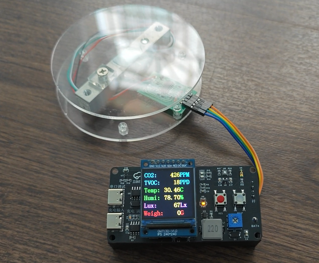
#9th LCSC Electronics Design Contest# Environmental Monitoring Clock and Scale
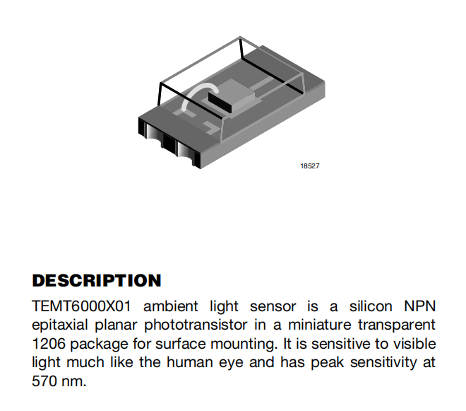
Monitors temperature and humidity (SHT40), CO2 concentration, volatile gases (SGP30), light intensity (TEMT6000), and battery level.
Features an RTC display; time can be modified via serial port.
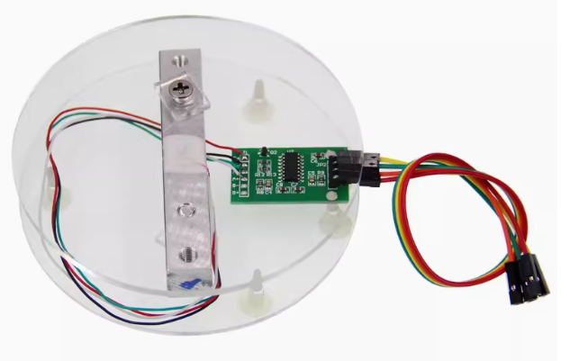
Capable of weighing up to 5 kg (HX711).
(FreeRTOS real-time operating system)
Video link: https://www.bilibili.com/video/BV1SAvre1Eah/?vd_source=bafd717f25f19c640ae97599d2643912
If all goes well, there will be a V2.0 version: https://oshwhub.com/keha/intelligent-control (I'm posting the link first, in case it's canceled)
Physical product image

1. Project function introduction
(FreeRTOS real-time operating system)
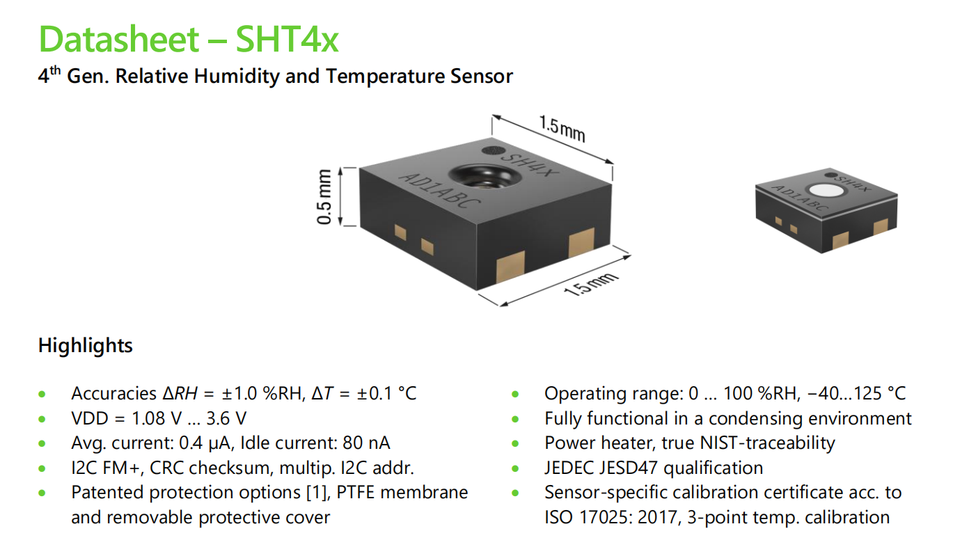
1. Temperature and humidity detection SHT40
2. Air quality detection SGP30, CO2 concentration, TVOC
3. Light intensity detection TEMT6000, illuminance range: 1-1000 lux
4. Electronic scale HX711, 5KG range (can use scales with other ranges)
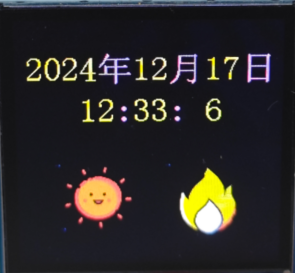
5. Clock display, the icon changes according to the set time and temperature, the time can be modified via serial port, no code modification required
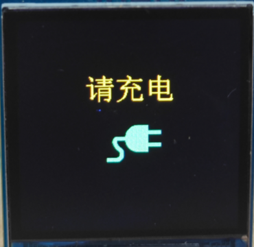
6. Battery powered with charging protection to prevent overcharging and over-discharging, and automatically controls the charging current. A charging prompt will appear when the battery is low.
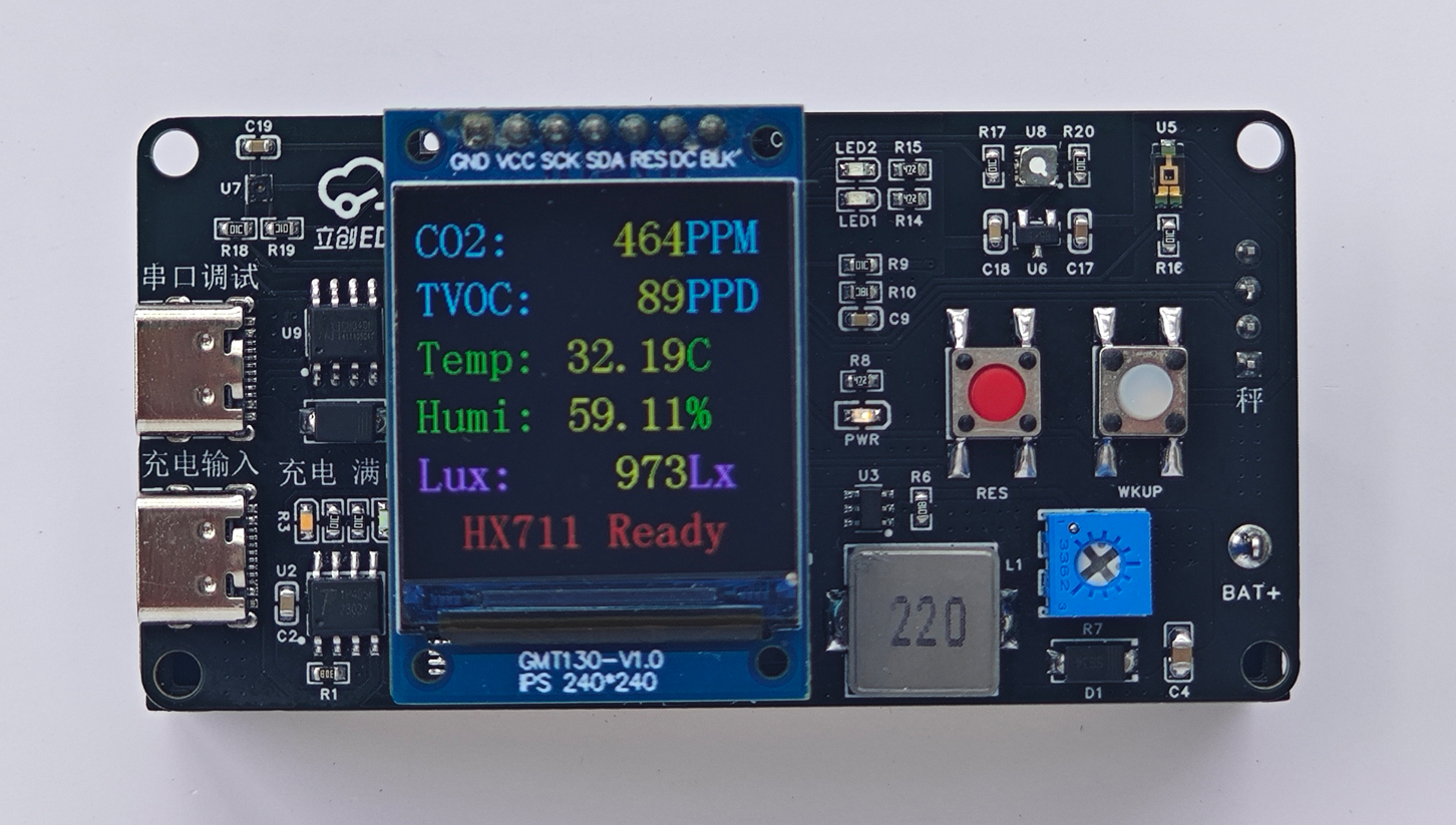
Sensor detection interface: (SGP30 initialization requires some time; HX711 will continuously display "Ready" if not connected, but will not display if the interface is switched.)

Time display: Displays the time and changes images according to day/night (sun and moon, code-defined). Displays three states based on temperature: hot, cool, and cold (customizable temperature).
Battery power detection: If using battery power, a prompt will appear to charge when the battery is low.
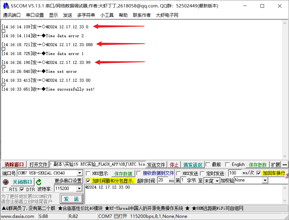
The RTC time can be changed via serial port without modifying the code. The serial data packet format is shown in the image: @2000.01.02.03.04.05.06 (with carriage return and line feed). Incorrect time format or time setting will be indicated.
2. Hardware Section
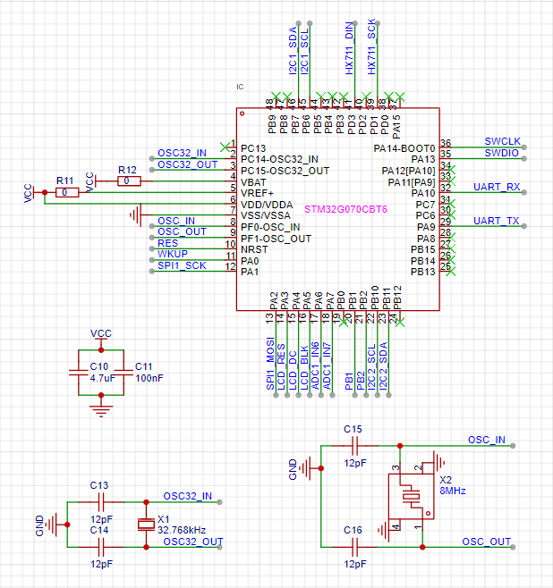
: 1. The main controller is selected as STM32G070CBT6. Originally, STM32G030C8T6 was used, but due to insufficient Flash and SDRAM for FreeRTOS and storing LCD images, it was replaced with STM32G070CBT6.
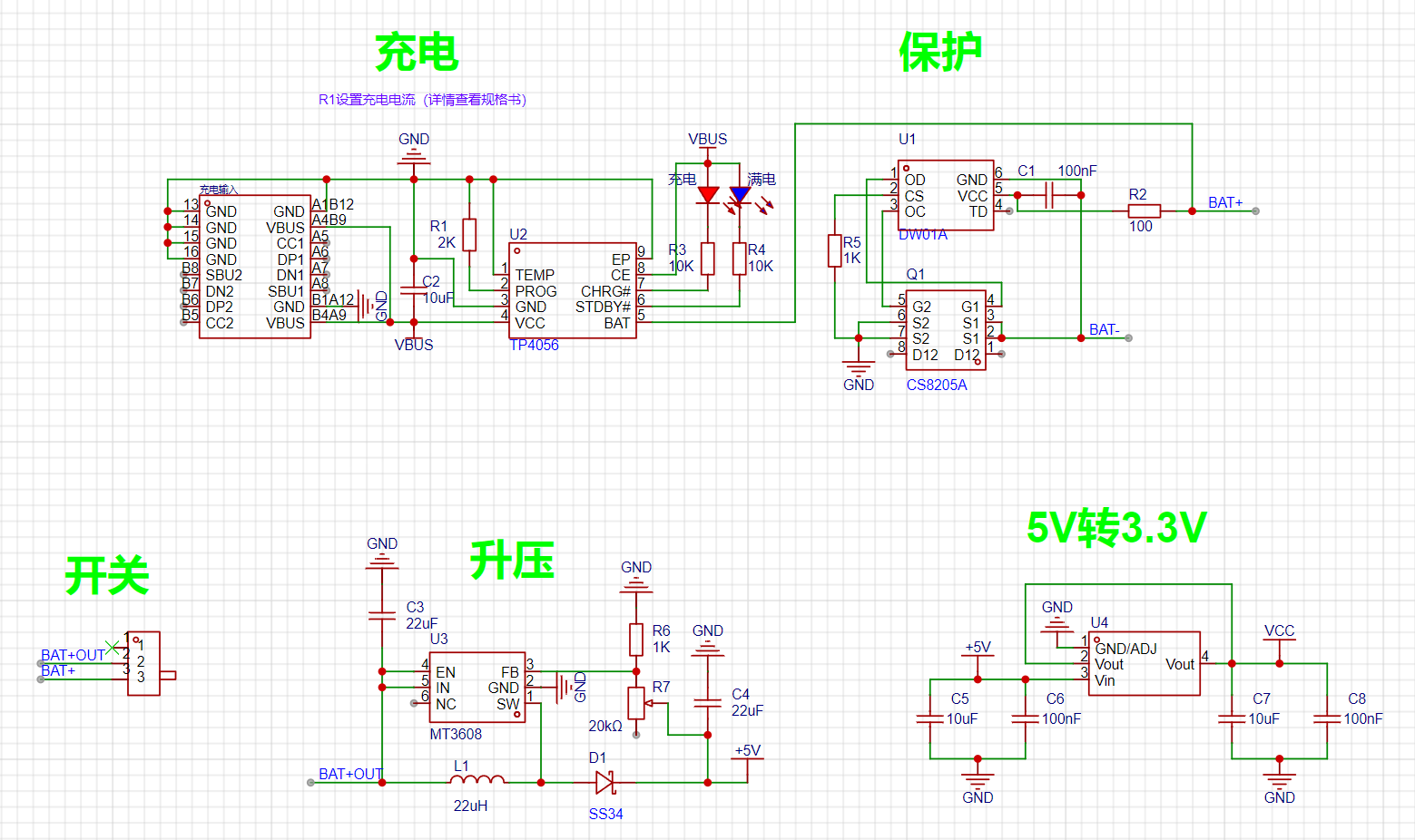
2. Power Input Section: Features charging protection to prevent overcharging and over-discharging of the battery, and automatically controls the charging current for better battery protection. Type-C female connector.
Maximum charging current: 1000mA;
Charging cut-off voltage: 4.2V;
Battery over-discharge protection voltage: 2.4V;
Maximum output current: 2A (recommended for use within 1A);
Output voltage: 4~12V (can be modified to higher output).
When the Type-C is connected to the power input terminal, the blue light illuminates and the red light flashes rapidly, indicating that power is connected. During battery charging, the red light remains on. The blue light illuminates when fully charged.
When a power source is connected to the charging input terminal, current is obtained from the power input terminal. If no power source is connected, current is obtained from the battery. The output automatically shuts off when the battery voltage drops below 2.4V.
Precautions:
When connecting the battery for the first time, there may be no voltage output. Power on the power input terminal to activate the protection circuit. When using a mobile phone charger, it must output at least 1A; otherwise, it may not charge properly.
The output voltage of this circuit is adjustable after boosting. When soldering, it is best to solder the power supply section first and adjust the boosted output voltage to 5V before soldering other circuits (adjust the output voltage to 5V after soldering other circuits, and then solder the AMS1117 3.3V last).
Pay attention to distinguishing the positive and negative terminals of the battery.
3. The serial port module for sensors and other circuits
can be used to modify the time or print debugging. The package includes a
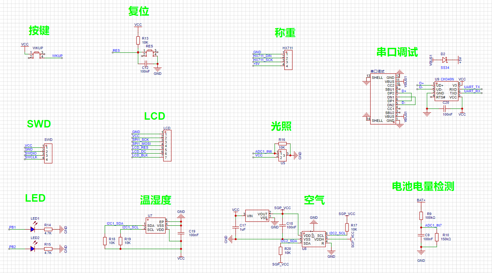
SHT40
SGP30

TEMT6000
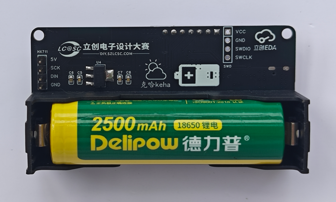
HX711 module + 5KG pressure sensor set, a
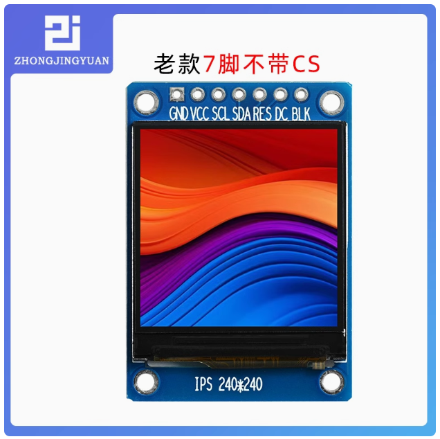
1.3-inch IPS TFT display, a 1.3-inch ST7789 IPS LCD screen, and
a single battery box. The battery box itself is a plug-in component and requires a slight modification: bend the negative pin to a surface mount.

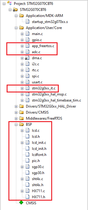
3. The software
code has been uploaded as an attachment, with extensive and detailed comments, a basic program for beginners using FreeRTOS.
The main program is primarily located in the app_freertos.c file.
The LCD, SHT40, SGP30, and HX711 drivers are in the BSP
light intensity and battery detection ADC-related sections in the adc.c file.
Serial port data packet processing for time modification is handled in the stm32gxx_it.c file
. Task 1: Relatively low priority, temperature and humidity detection and display.

Task 2: Relatively low priority, CO2 and TVOC concentration detection and display (SGP30 requires initialization for a period after power-on).

Task 3: Relatively low priority, light intensity and battery level

detection and display (light intensity conversion is detailed in the documentation). Task 4: Relatively low priority, weighing measurement and display.

The weighing module requires calibration; see the documentation > HX711 for details.

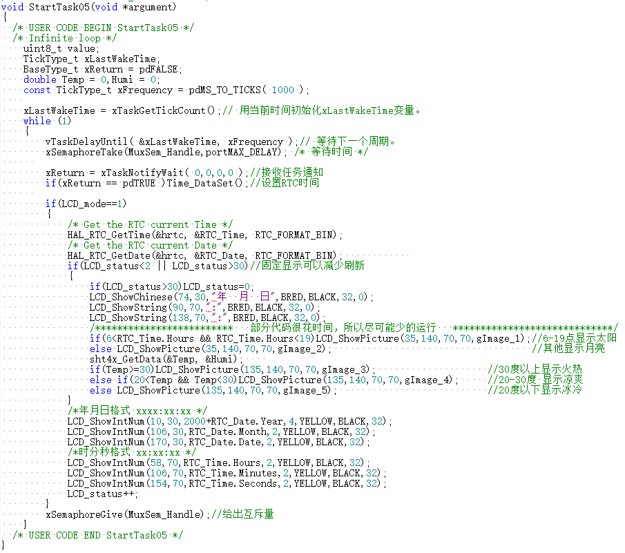
Task 5: Relatively medium priority, displaying time and updating the display time every second; the display icon changes according to time and temperature.
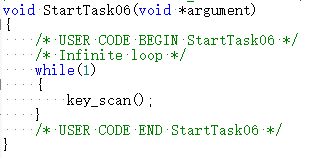
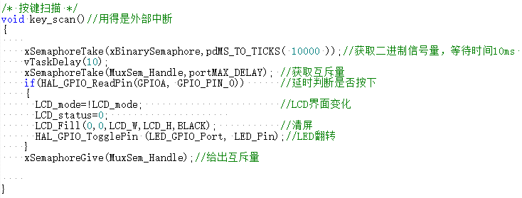
Task 6: Relatively high priority, detecting button presses (external interrupt).
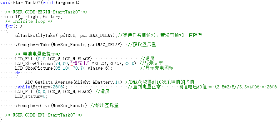
Task 7: Relatively high priority, but requires notification to execute; if low battery is detected, prompt for charging.
4. References
and Attachments
Environmental monitoring clock and data. 7z
STM32G070CBT6 Environmental Monitoring Clock and Scale. 7z
Weight Measurement.mp4
PDF_#9th LCSC Electronics Contest# Environmental Monitoring Clock and Scale.zip
Altium_#9th LCSC Electronics Contest# Environmental Monitoring Clock and Scale.zip
PADS_#9th LCSC Electronics Contest# Environmental Monitoring Clock and Scale.zip
BOM_#9th LCSC Electronics Design Contest# Environmental Monitoring Clock and Scale.xlsx
93364
#9th LCSC Electronics Contest# Temperature and Humidity Measurement
The STM32G030K6T6 chip is used as the main control chip; the digital tube displays the temperature and humidity values; it is in low-power sleep mode when powered on, and enters running mode when the user presses a button, that is, the displayed values are switched at certain time intervals, and it will enter low-power sleep mode after the display ends.
* 1. Project Function Introduction:
The temperature and humidity measuring instrument project uses the STM32G030K6T6 chip as the main control chip, with an Arm Cortex-M0+ core, a maximum clock frequency of 64MHz, 32KB of Flash, 8K of SRAM, and a power supply voltage of 2.0V~3.6V.
It uses IIC communication to collect temperature and humidity data from the SHT40 sensor and displays the data through a digital tube.
During idle time, it enters a low-power sleep mode; pressing a button enters normal operation mode, and after operation, it automatically enters low-power sleep mode, waiting to be woken up by pressing a button.
It is powered by a lithium battery, with an onboard dual power supply automatic switching circuit: lithium battery (3.0-4.2V) and Type-C power supply (5V).
The Type-C interface is used to charge the lithium battery and power the operating circuit.
Function Demo: https://b23.tv/9zeGwvK
*2. Project Attributes
Revealed for the First Time
* 3. Open Source License:
GPL 3.0 ,
Third Edition, GNU General Public License, released by the Free Software Foundation (FSF).
If a product under the GPL license is used in an engineering project, then the project must also use the GPL license, which means: open source and free.
>
Open source license explanation link: LCSC Open Source Hardware Platform Announcement [Help Document] Open Source Hardware Platform Open Source License Explanation
*4. Hardware Part
MCU Circuit
STM32G030K6T6, NRST default pull-up reset, external LSE clock source 32.768kHz

Figure 1 MCU Main Control Circuit Diagram

Figure 2 MCU Internal Structure Block Diagram
Temperature and Humidity Sensor Circuit + Power Monitoring Circuit + Operation Indicator Circuit
SHT40-AD1B Sensor Chip, I2C Communication Interface Default Pull-up; Main Circuit Series Equivalent Resistor Voltage Divider, Branch Circuit ADC Acquisition; Button Operation + LED Indicator
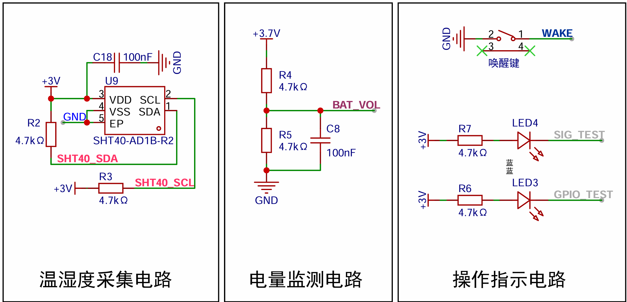
Figure 3 Temperature and Humidity Sensor Circuit, Power Monitoring Circuit, Operation Indicator Circuit Diagram

Figure 4 Pseudo Code Provided by SHT40 Sensor Manual

Figure 5 I2C Communication Code
I2C (Inter-Integrated Circuit): A commonly used synchronous serial communication protocol.
I2C devices are connected to the bus through open-collector or open-drain pins, pulling the line low.
When there is no data transmission, the I2C bus is in a high-level idle state due to the external pull-up resistors on the circuit.
When data transmission is needed, the level is first pulled low and then released (returning to the initial state: high level), and the data bits are transmitted on the falling edge generated by SDA under the SCL clock signal.
Hardware I2C does not require viewing the specific communication timing of the I2C device; it is handled by the hardware.
Simulated I2C requires attention to the communication timing of the I2C device, simulating its timing to achieve communication.

Figure 6 shows a schematic diagram of the I2C connection .
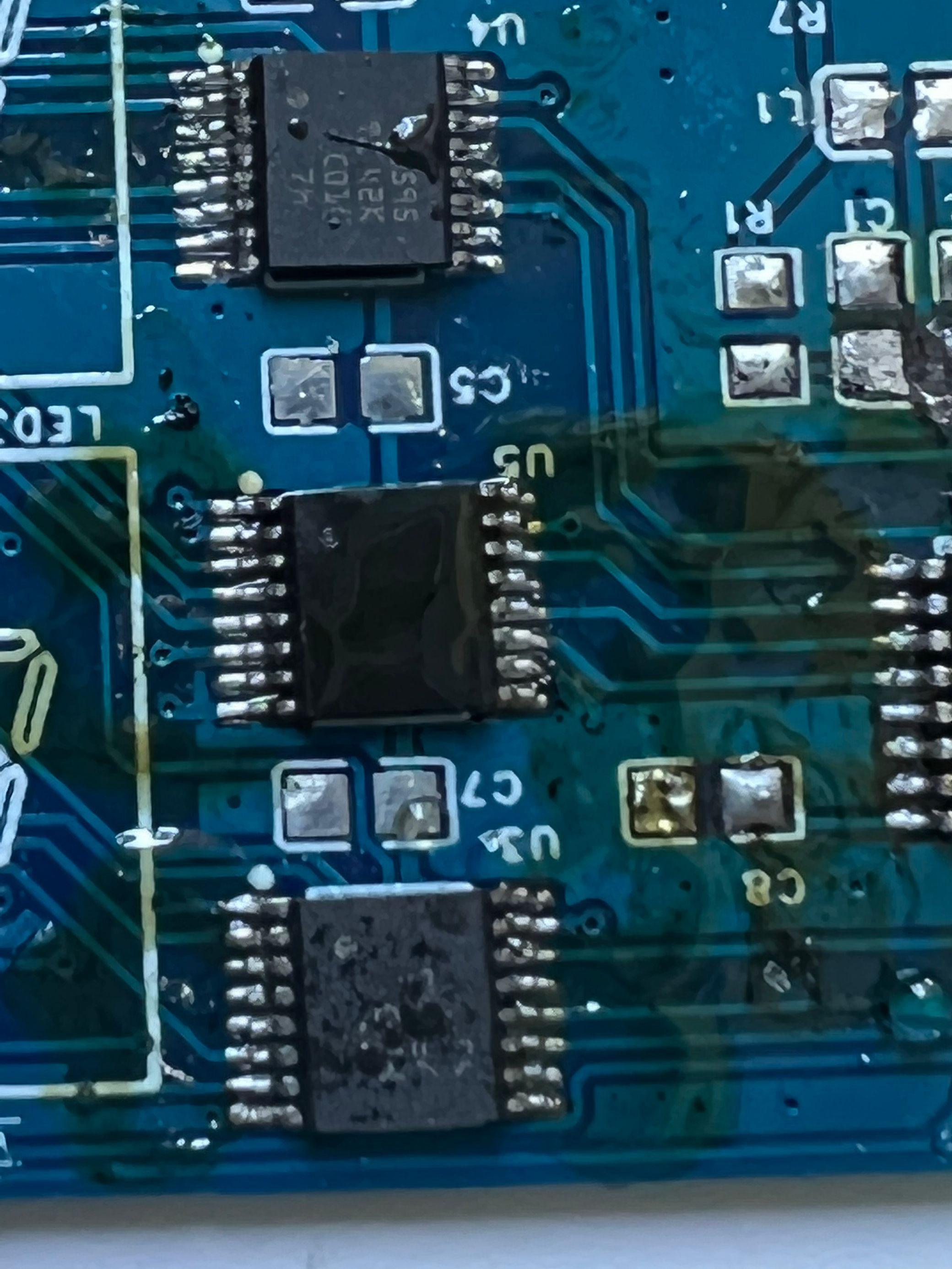
The digital tube driver circuit
consists of three 74HC595 chips to display two three-digit digital tubes.
One 74HC595 chip is used to control the common cathode port of the digital tube LED, and the other two 74HC595 chips are used to control the positive port of the digital tube.
When LEDx_n (x: 1-2, n: AH) outputs a high level and LEDx_DIGn (x: 1-2, n: 1-3) is controlled to a low level, the corresponding LED inside the digital tube is turned on, i.e., lit.
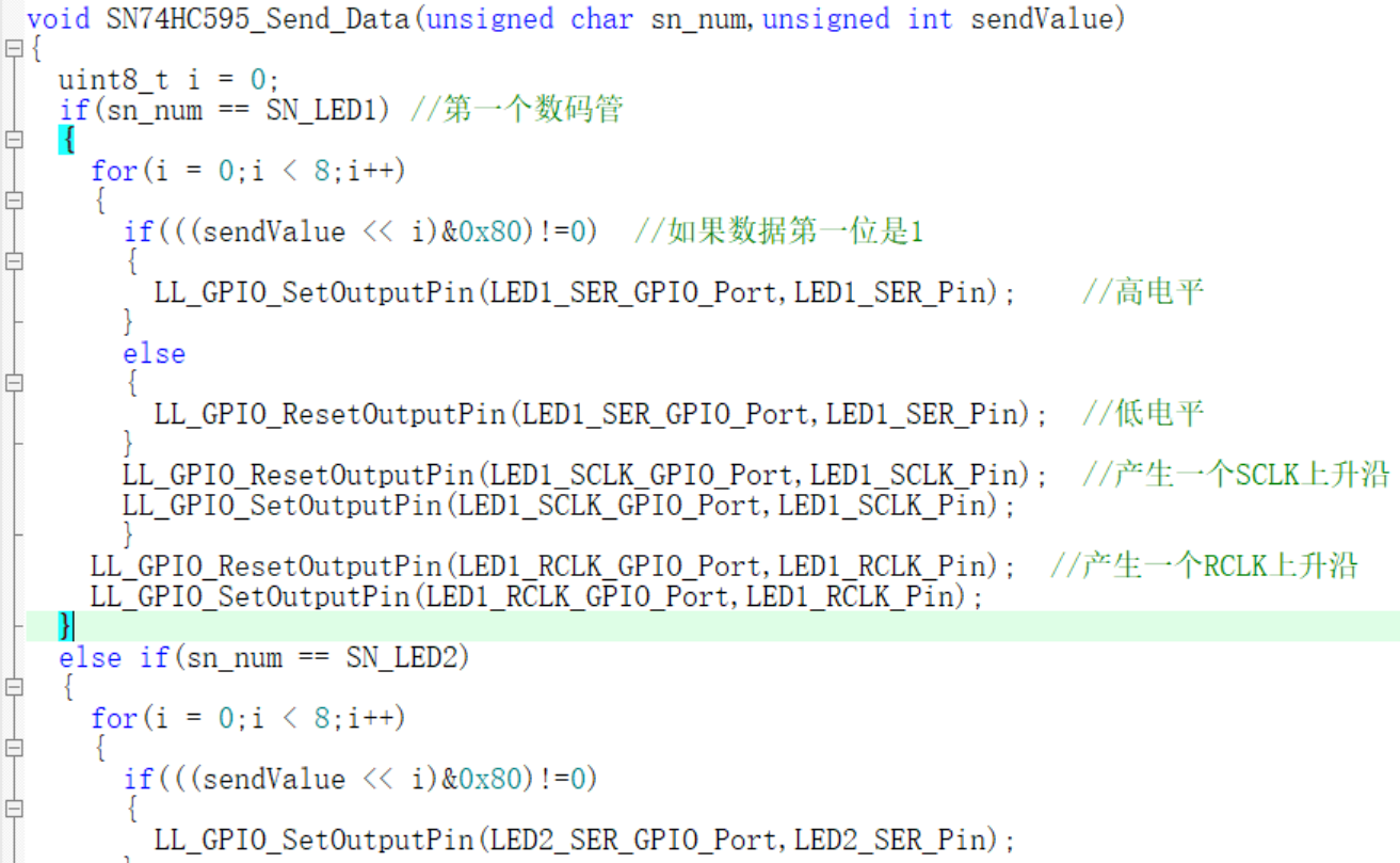
The 74HC595 chip consists of a shift register and an output register. The shift register receives serial input data and performs shift operations, while the output register latches the data in the shift register and provides parallel output. Data is serially input into the shift register via the SER pin. The SRCLK pin provides a clock signal; when the rising edge of the signal arrives, the data in the shift register is shifted. When data needs to be latched, a clock signal is provided using the RCLK pin. When the rising edge of the signal arrives, the data in the shift register is latched into the output register.
(Transmission occurs one bit at a time, with a total of one byte transmitted each time; 1 byte = 8 bits)

Figure 7: Digital tube driver circuit diagram. Lithium battery
charging
circuit: The lithium battery charging circuit uses the TC4056A chip. The charging current is controlled by adjusting the resistance value of R11. Formula: I = 1200/Rprog (current unit: mA; resistance unit: kΩ)
Charging state: CHRG is low level, STDBY is high level, i.e. (red light on, green light off).
Fully charged state: STDBY is low level, CHRG is high level, i.e. (green light on, red light off).

Figure 8 Lithium battery charging circuit
diagram 1 TC4056A status table
Charging state
Red light CHRG (7 pins)
Green light CHRGT (6 pins)
Charging On Off Battery fully charged Off
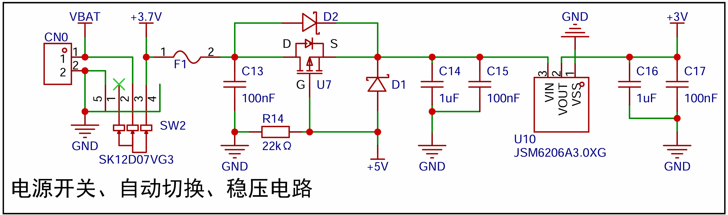
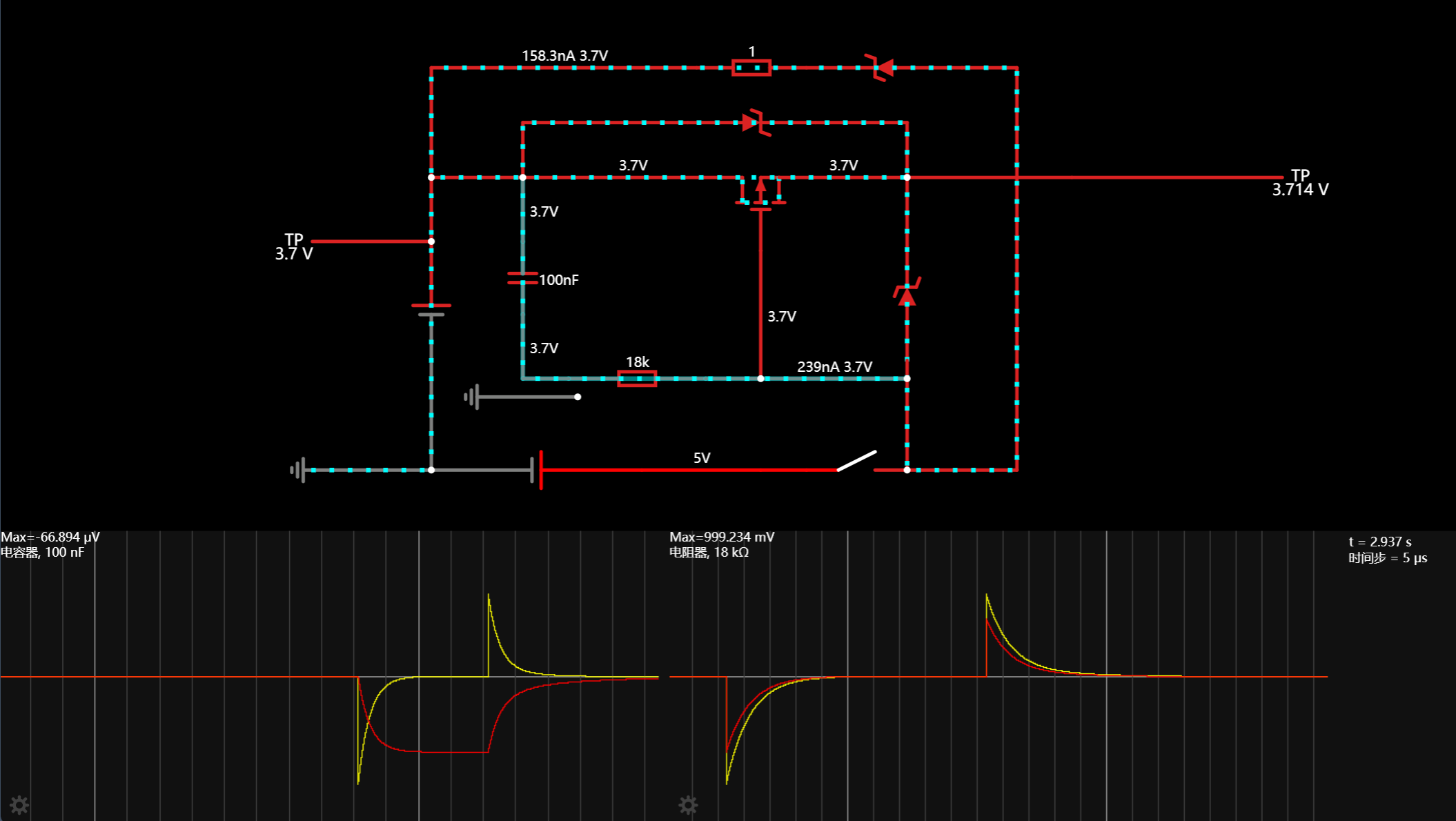
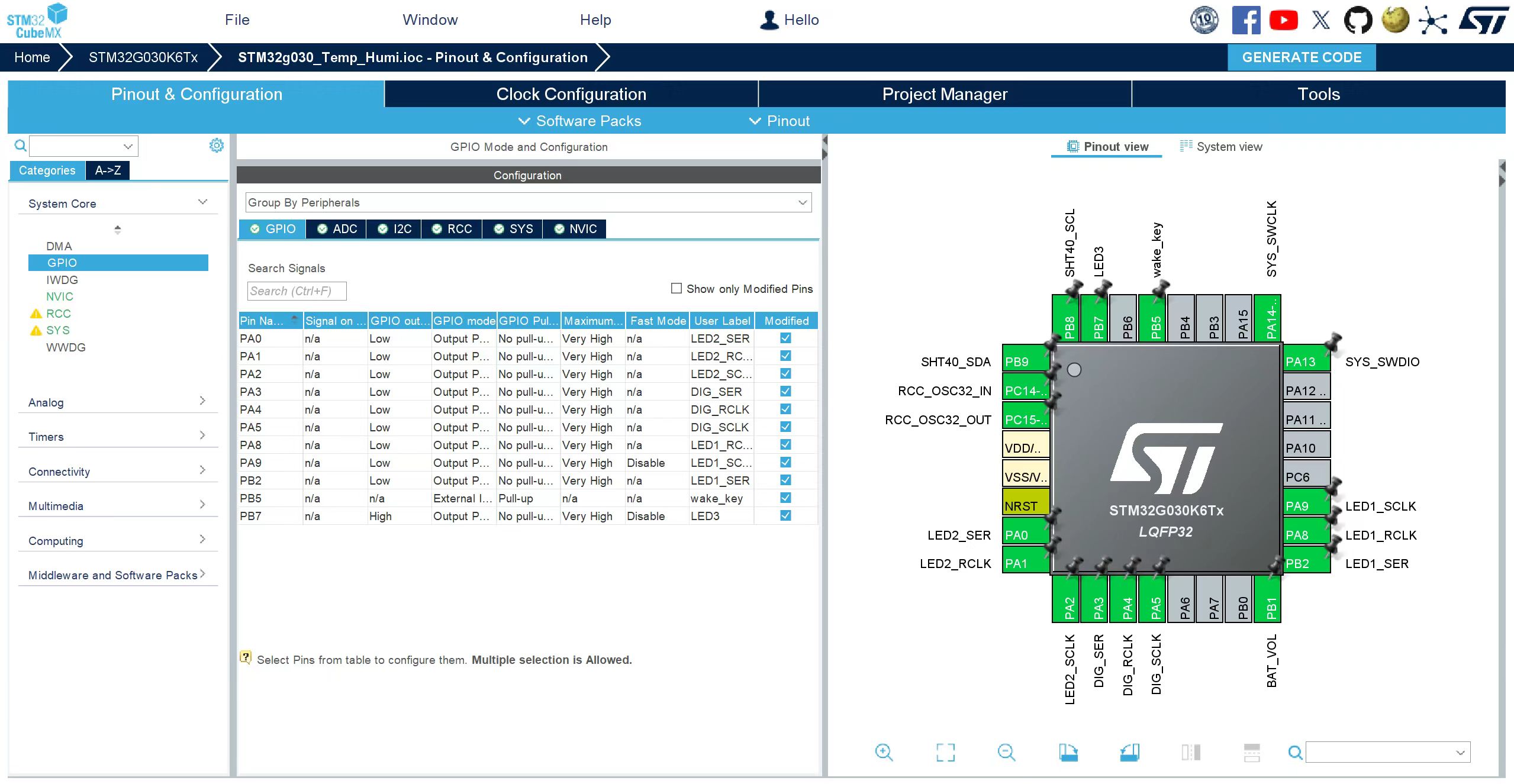
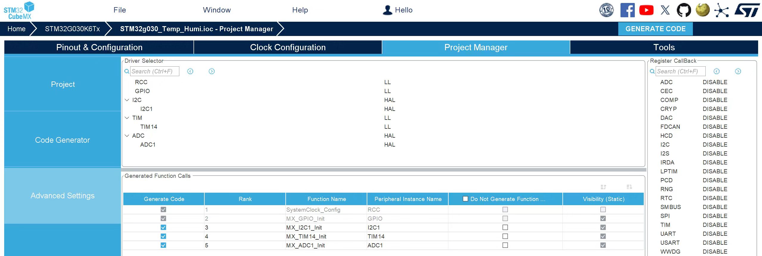
VCC = 5V Battery reversed Off VCC =5V No battery connected Off (*) After the battery is reversed , the LED display will remain completely off. It can only be restored to other states after the battery is connected correctly, or it can be restored after disconnecting the battery and waiting for 10 seconds. When the 5V port is floating, the gate of the PMOS transistor is pulled down to ground (0V) through resistor R14. The lithium battery BAT (3.7~4.2V) reaches the source through the internal body diode of the PMOS transistor, and the source voltage is (3~3.5)V. At this time, Ugs is (-3.5)V to (-3)V. When 5V is connected, Ugs reaches the source through diode D1, and the source voltage is 4.3V. The gate voltage is 5V, Ugs=5-4.3=0.7V>Uth. At this time, the MOS transistor is turned off, and the output Vout=4.3V(5-0.7). Diode D2 acts to increase discharge and reduce power switching time. Note: The voltage difference between the two power supplies must be greater than 0.7. This circuit is referenced from the external power supply and lithium battery automatic switching circuit diagram 9 shows the power supply circuit diagram. Online simulation of the circuit shows that the dual power supply switching time is approximately 10ms (100nF capacitor + 18kΩ resistor). In the circuit diagram above, if C13 = 220nF and R14 = 10kΩ, after simulation, the switching time is approximately 20ms, i.e., 50Hz. Figure 10 Automatic Power Switching Simulation Diagram *5, Software Part: STM32CubeMX Configuration Project Code
For detailed configuration, please refer to the attached IOC file.
MDK programming project main
program >>
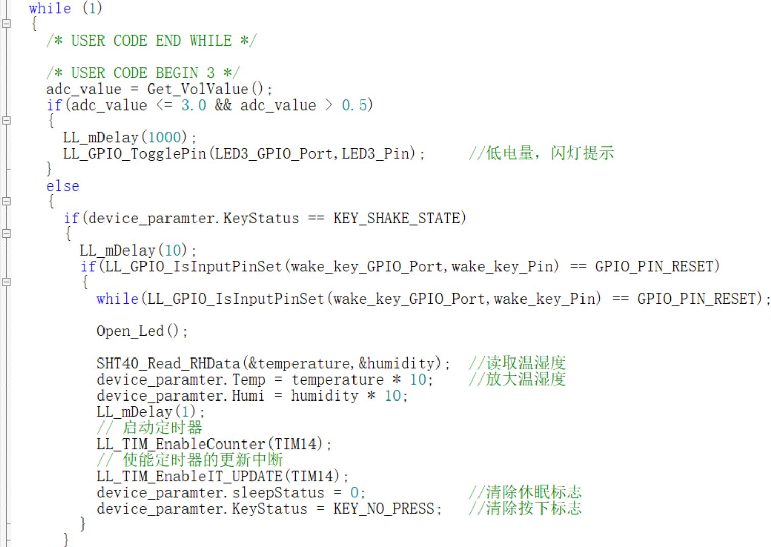

Partial digital tube driver code >>
Obtain SHT40 sensor temperature and humidity data >>
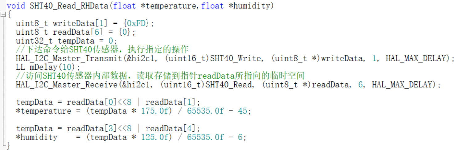
ADC voltage acquisition >>
volvalue = (adc_value*(3.03F-0.15F))*2/4095.0F.
In the ADC acquisition circuit seen earlier, two equal resistors in series divide the voltage of the lithium battery in this part, so the ADC acquires half of the total voltage. Here, *2 is used.
The actual measured MCU voltage VDD/VDDA is 3.01V. The subtracted 0.15 is considered an error (I previously tried using an HK chip for ADC voltage acquisition, achieving accuracy to three decimal places, but ADC testing on this current MCU revealed a significant error; the specific reason is unknown).
The STM32G030's ADC resolution is 12 bits, so 4095 = 2^12 - 1. This indicates that the internal voltage of 3V can be divided into 4095 parts, each representing 0.000732 volts (V). The formula in the code is essentially a proportional transformation.
Note: The voltage of the object being measured must not exceed VDD; otherwise, the measured power supply voltage will be inaccurate because it exceeds the measurement range!


*6. BOM List
Number
Quantity
Remarks
Tag Number
Package
Value
LCSC Item Number LCSC
Price
Manufacturer
Material Cost
1
9
100nF
C1,C2,C8,C10,C12,C13,C15,C17,C18
C0603
100nF
C14663
0.013981
YAGEO
0.125829
2
2
20pF
C3,C4
C0603
20pF
C105621
0.014605
YAGEO
0.02921
3
5
1uF
C5,C6,C7,C14,C16
C0603
1uF
C59302
0.030538
FH
0.15269
4
2
10uF
C9,C11
C0603
10uF
C77044
0.067488
muRata (村田)
0.134976
5
1
HC-XH-2AW-G
CN0
CONN-TH_2P-P2.50_HC-XH-2AW-G
C5341208
0.107373
HCTL (华灿天禄)
0.107373
6
2
MBR120LSF
D1,D2
SOD-123_L2.8-W1.8-LS3.7-RD
C130880
0.2192
SHIKUES (时科)
0.4384
7
1
BSMD0805-050-6V
F1
F0805
C883108
0.276183
BHFUSE (佰宏)
0.276183
8
1
CBG160808U000T
L1
L0603
C43163
0.024165
FH (Fenghua)
0.024165
9
2
SP420281N
LED1,LED2
LED-SEG-TH_SP420281N
C122944
2.1663
ARKLED (Fangzhou)
4.3326
10
2
XL-1608UBC-04
LED3,LED4
LED0603-RD_BLUE
C965807
0.02253
XINGLIGHT (Chengxingguang)
0.04506
11
1
SZYY0603R
LED5
LED0603-R-RD
C434419
0.041609
yongyu (Yongyu Optoelectronics)
0.041609
12
1
XL-1608PGC-06
LED6
LED0603-RD_GREEN
C7371905
0.0586
XINGLIGHT (成兴光)
0.0586
13
4
M2
P1,P2,P3,P4
M2
0
0
14
3
10kΩ
R1,R8,R13
R0603
10kΩ
C25804
0.005579
UNI-ROYAL (Thick Sound)
0.016737
15
6
4.7kΩ
R2,R3,R4,R5,R6,R7
R0603
4.7kΩ
C23162
0.006472
UNI-ROYAL (Thick Sound)
0.038832
16
2
5.1kΩ
R9,R10
R0603
5.1kΩ
C23186
0.006186
UNI-ROYAL (Thick Sound)
0.012372
17
1
2.4kΩ
R11
R0603
2.4kΩ
C22940
0.006003
UNI-ROYAL (Thick Sound)
0.006003
18
1
250mΩ
R12
R0603
250mΩ
C422951
0.022713
UNI-ROYAL (Thick Sound)
0.022713
19
1
22kΩ
R14
R0603
22kΩ
C31850
0.006147
UNI-ROYAL (Thick Sound)
0.006147
20
1
GT-TC054A-H035-L1
SW1
SW-SMD_L7.8-W3.5-P4.20-EH
C778158
0.24573
G-Switch (Pinzan)
0.24573
21
1
SK12D07VG3
SW2
SW-TH_SK12D07VG3
C431547
0.130586
SHOU HAN
0.130586
22
2
Test-Point
SWCLK,SWDIO
Test-Point-0.5mm
0
0
23
1
STM32G030K6T6
U1
LQFP-32_L7.0-W7.0-P0.80-LS9.0-BL
C529331
4.7
ST (STMicroelectronics)
4.7
24
3
SN74HC595PWR
U2,U3,U4
TSSOP-16_L5.0-W4.4-P0.65-LS6.4-BL
C273642
1.2759
TI (Texas Instruments)
3.8277
25
1
GT-USB-7002C
U5
USB-C-SMD_GT-USB-7002C
C5117884
0.417367
G-Switch (Pinzan)
0.417367
26
1
TC4056A
U6
ESOP-8_L4.9-W3.9-P1.27-LS6.0-BR-EP3.3
C84051
0.312037
FM (Fuman)
0.312037
27
1
AO3401-ED
U7
SOT-23-3_L2.9-W1.3-P0.95-LS2.4-BR
C4748724
0.112913
HXY MOSFET (Huaxuanyang Electronics)
0.112913
28
1
SHT40-AD1B-R2
U9
DFN-4_L1.5-W1.5-P0.8-TL-EP
C2909890
11.51
Sensirion (Switzerland)
11.51
29
1
JSM6206A3.0XG
U10
SOT-23-3_L2.9-W1.6-P1.90-LS2.8-BR
C2845116
0.191449
JSMSEMI (杰盛微)
0.191449
30
1
32.768kHz
X1
OSC-SMD_L3.2-W1.5
32.768kHz
C390740
1.2448
JGHC (晶光华)
1.2448
Total:
61
Total Price:
28.562081 (excluding lithium battery)
MCU and SHT40 can be purchased on Taobao for less than 3.00 yuan each, and 3 digital tubes for less than 1.5 yuan each.
If we exclude the MCU, digital tubes, and SHT40, then we get: 7.469403
7.469403 + 3 + 1.5 = 11.969403.
Some components can be further reduced; the estimated total price (excluding lithium battery) is at least less than 12 yuan.
*7. Competition logo verification.
*8. Demo your project and record a video for upload.
STM32g030_Temp_Humi.ioc
STM32g030_Temp_Humi_Project.7z
Temperature and humidity measurement demonstration video.mp4
PDF_#9th LCSC Electronics Design Contest# Temperature and Humidity Measurement.zip
Altium_#9th LCSC Electronics Contest# Temperature and Humidity Measurement.zip
PADS_#9th LCSC Electronics Contest# Temperature and Humidity Measurement.zip
BOM_#9th LCSC Electronics Design Contest# Temperature and Humidity Measurement.xlsx
93365
STC8H8K64U Development Board
The programming for the base plate, top plate, and intermediate expansion board
is relatively basic; the test code is two days late.
Currently, the base plate B0 and top plate B1 have been completed.
Base plate B0 is a minimal system with no crystal oscillator and
onboard buttons and LED indicators. Top plate B1 has an onboard 5-digit LED display, 8-digit buttons, 8+1 LEDs, and a buzzer.
MCU baseboard (tested code attached):
Onboard USB and USB serial ports
; onboard DC power supply and power switch;
onboard buttons (tested with code) and LEDs (tested with code);
no crystal oscillator.
Top board: Buttons, digital tube, running lights, buzzer (tested code attached).
74HC165 8-button readout (tested with code)
(Supports interrupts (not tested with code));
74HC4094
driver for 5-digit digital tube (tested with code);
8-digit running lights (tested with code);
1-digit test LED (tested with code);
Buzzer driver (tested with code)
(not yet built). Middle layer 16-input
plan: !! Optically isolated 16-input 74HC165 readout.
a19d9d12f568bb7c5ea46f9ba2882f5e.mp4
b33bd7f13fb1b0252a91adfed69a5d76.mp4
STC8H8K64U.7z
PDF_STC8H8K64U development board.zip
Altium_STC8H8K64U development board.zip
PADS_STC8H8K64U development board.zip
BOM_STC8H8K64U Development Board.xlsx
93367
#9th LCSC Electronics Design Contest# Temperature and Humidity Measuring Instrument
Temperature and humidity detector based on STM32G030K6T6 chip and Sensory sensor.
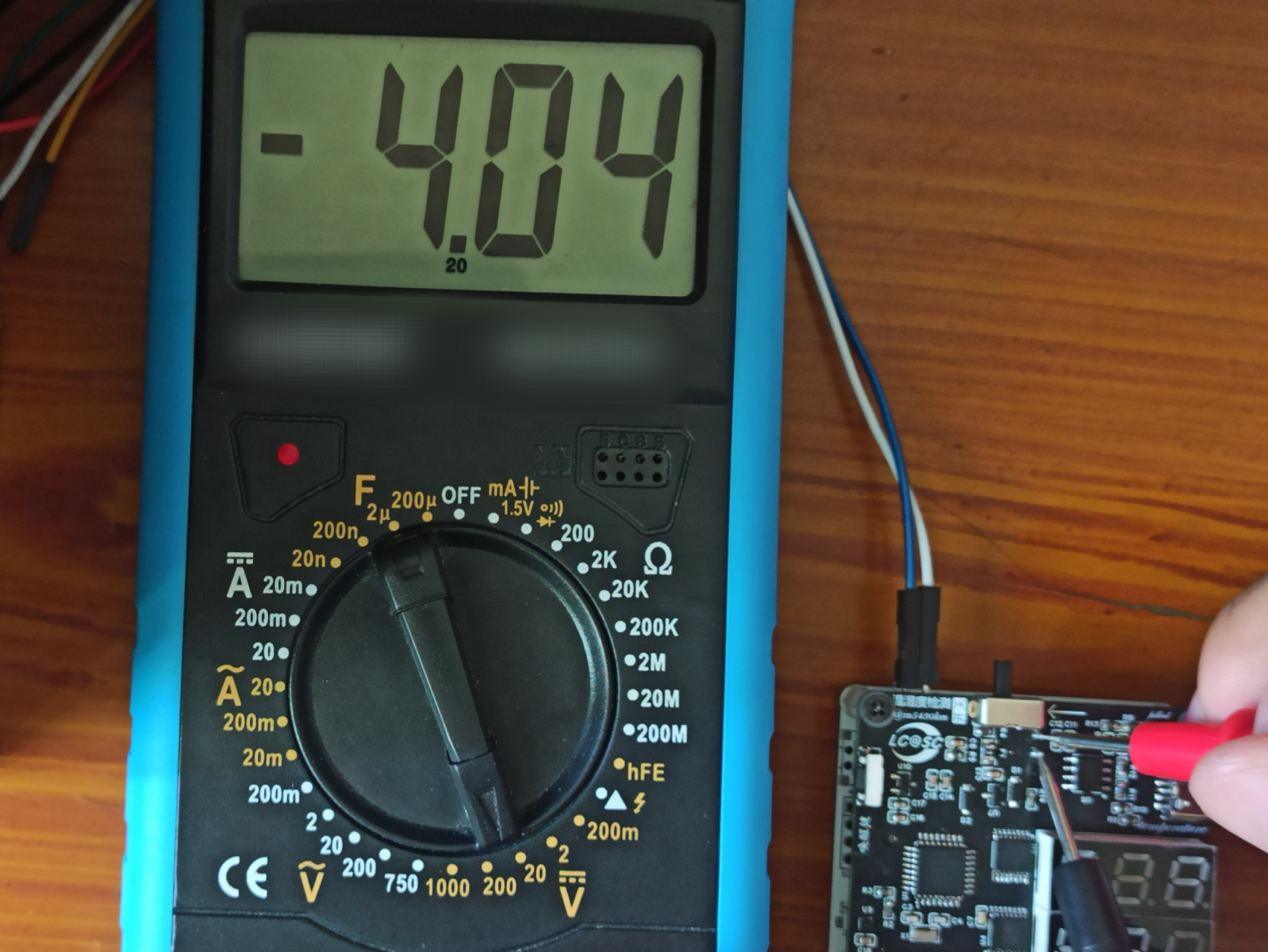
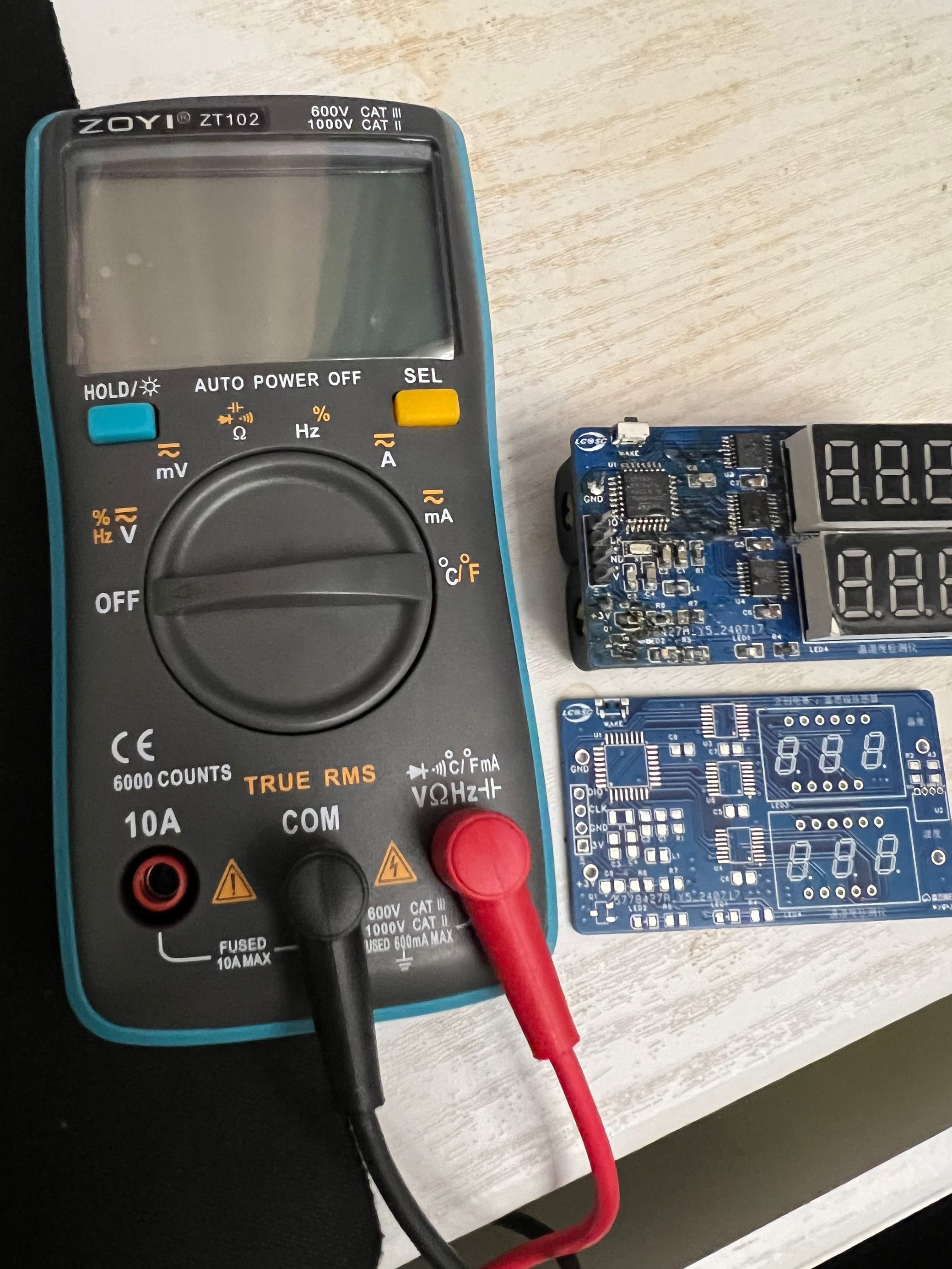
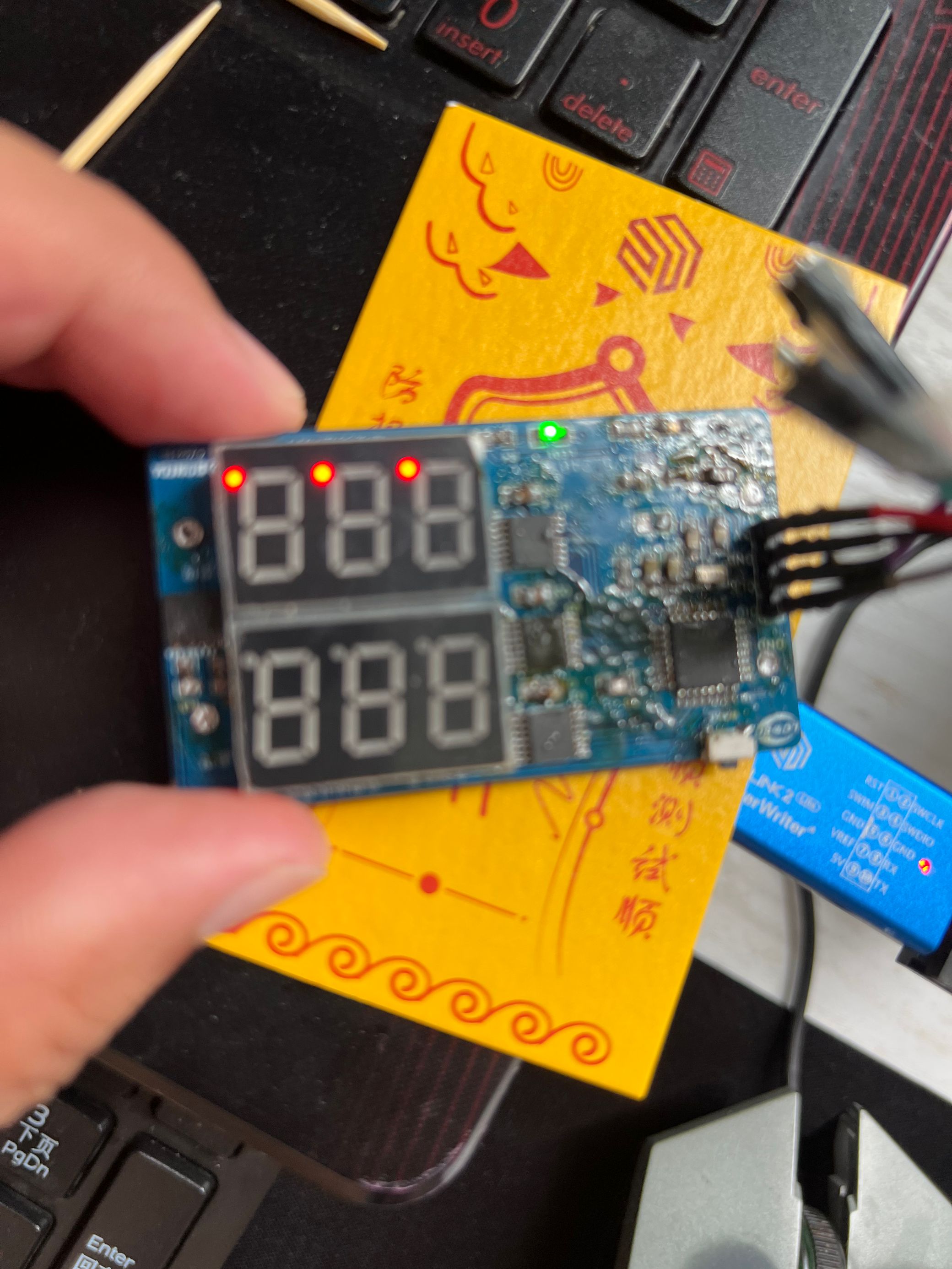
The problem description for
the 9th LCSC Electronics Design Contest is as follows : This is a temperature and humidity meter developed using the STM32G030K6T6 chip as its core and the Sensirion SHT40 temperature and humidity sensor module. The schematic design is as follows: This temperature and humidity meter is developed using the STM32G030K6T6 chip as its core and the Sensirion SHT40 temperature and humidity sensor module. It transmits data via the MCU's IIC protocol and uses three tri-state 8-bit shift registers to drive two digital tubes for display. PCB Design Description: The PCB layout, wiring, line width, spacing, etc., are designed according to the professional standard. No special software is required . The software uses the official training camp examples… Physical Demonstration: Start soldering with the contest logo . It's been a while since I've used my hands, so I'm a bit rusty. A friend in the group said to use wire drawing soldering, hahaha. Precautions: For multi-pin chips, the soldering temperature must be set higher. Use a soldering tool or horseshoe tip with soldering flux for drag soldering. The speed must be fast; otherwise, the chip will be damaged by overheating. The demonstration video was full of twists and turns; the battery holder was soldered backwards. Luckily, it had reverse polarity protection. After soldering it, the MOSFET got hot, so I removed it, but it still got hot. I removed the capacitor, but that didn't work either. Finally, I had to buy a multimeter. A friend in the group recommended it; it's very compact and only cost 55 yuan—great! I uploaded other attachments and measured for short circuits. After another round of disassembly, nothing worked. Finally, I removed the battery holder, and it turned out the sensor header was short-circuited. I applied rosin and resoldered it, and the short circuit was gone! OK! With the short circuit resolved, I powered it on, and the LED and digital display lit up. I tried programming, but there was no connection. I resoldered the chip again, and the programming was successful.


trim.6C60DE73-7A47-4B47-BF9C-6642B8CC47E7.MOV
Project.uvprojx
PDF_#9th LCSC Electronics Contest# Temperature and Humidity Measuring Instrument, .zip
Altium_#9th LCSC Electronics Contest# Temperature and Humidity Meter, .zip
PADS_#9th LCSC Electronics Contest# Temperature and Humidity Meter, .zip
BOM_#9th LCSC Electronics Contest# Temperature and Humidity Measuring Instrument, .xlsx
93369
#9th LCSC Electronics Contest# Temperature and Humidity Measuring Instrument
This was my first time participating in the 9th LCSC Electronic Design Contest, and I gained a lot. The project was to create a compact desktop temperature and humidity monitor, using a Sensirion temperature and humidity sensor to acquire temperature and humidity data and display it on a digital tube. I am very grateful to LCSC for providing this great platform that allowed me to learn about electronics!
* 1. Project Function Introduction
This project uses an STM32G030K6T6 chip as the main controller, acquiring data from a Sensory temperature and humidity sensor and displaying it on a digital tube. Considering power consumption, a sleep mode was implemented, which is off by default. The chip is woken up by a button to collect data and display it on the digital tube. The power module uses two AA batteries, providing approximately 3V. In our sleep/wake-up mode, these two batteries can last a very long time.
This project is very simple to replicate. I am a beginner myself, and the functionality is relatively basic. Experienced developers can add other functions and sensors.
This compact desktop temperature and humidity monitor doesn't take up much space; it can beautify your desktop as a small decorative item and also provide a fun way to check the current temperature and humidity. DIYing one is a great decision.
*2. Project Attributes
This project is being publicly disclosed for the first time, but it is not an original work; it is a replication of a solution provided by the LCSC platform. It has not yet won any awards.
* 3. Open Source
License: Public Domain: https://creativecommons.org/share-your-work/public-domain/
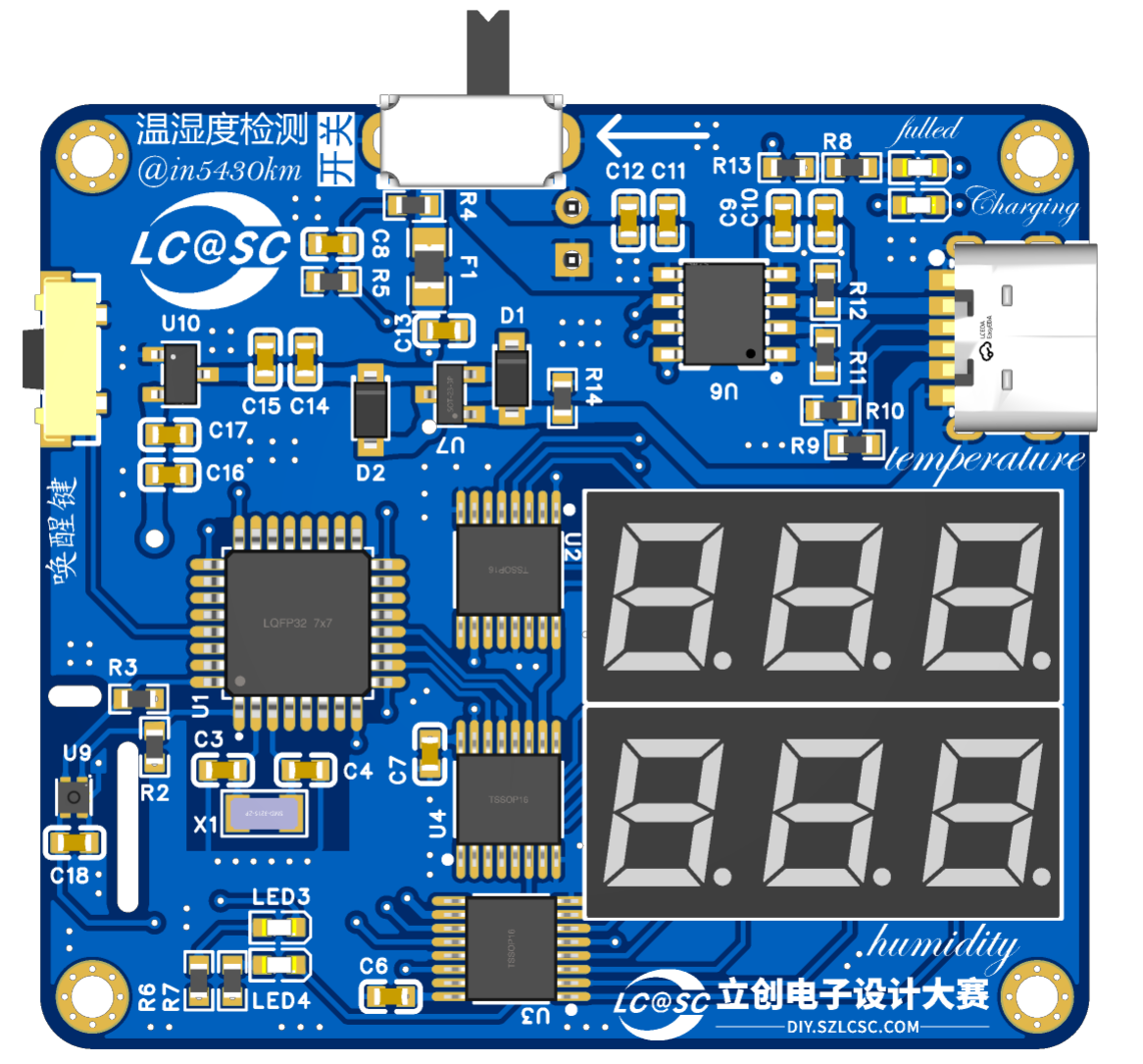
* 4. Hardware
Schematic:
PCB:

2D Plane View:

3D Front View:

3D Back View:

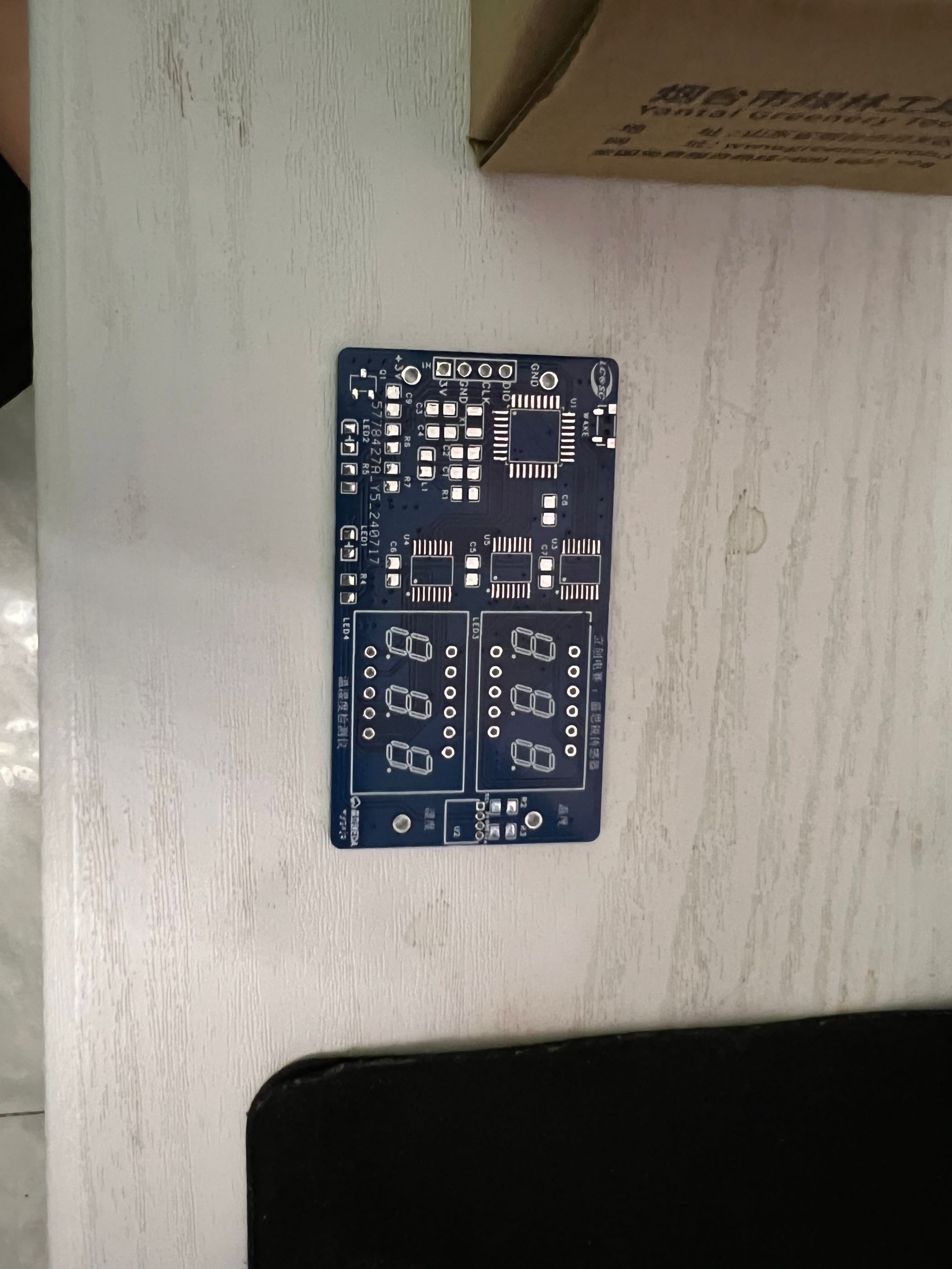
Actual Image:

* 5. Software:
Most of the code was debugged based on the code provided by Mr. Chen. Since I'm replicating it, there's almost nothing that needs modification. However, it's best to review the chip's sleep mode principle and code before programming. Otherwise, directly programming will cause significant problems, preventing you from programming again. You need to program within the few seconds of the active state. Also, check the crystal oscillator used. Inconsistent frequencies in the code can cause the chip to lock up; I encountered this problem. Next, let's look at the sleep modes:
The STM32G0 series has four sleep modes:
Low-power operation mode (reduces CPU frequency, but the system is still running)
, Sleep mode (the system enters sleep mode and can be woken up by any interrupt/event)
, Stop mode (the system enters stop mode and supports any external interrupt and RTC alarm wake-up) , and
Standby mode (the system enters standby mode and supports RTC alarm wake-up, WKUP, NRST pin wake-up, and IWDG reset wake-up; LSI and LSE are enabled).
Note that none of these modes can be used for debuggering, as the system clock is turned off; and after setting it to low-power mode, code cannot be downloaded until it is woken up. For detailed instructions, please refer to the specific datasheet.
Please set the modes according to your actual situation, and set the synthesis code to sleep mode.
*6. BOM list
is attached
*7. Competition LOGO verification

*8. Demonstrate your project and record a video to upload
(see attachment)
Project.7z
BOM_Board1_PCB1_2024-07-29.xlsx
LCSC Electronics Contest: Temperature and Humidity Monitor.mp4
PDF_#9th LCSC Electronics Design Contest# Temperature and Humidity Meter.zip
Altium_#9th LCSC Electronics Design Contest# Temperature and Humidity Monitor.zip
PADS_#9th LCSC Electronics Design Contest# Temperature and Humidity Monitor.zip
BOM_#9th LCSC Electronics Design Contest# Temperature and Humidity Monitor.xlsx
93371
DRV8313 driver system board
The DRV8313 minimum system board was rarely available for purchase, and the shipping cost was higher than the board itself, so I decided to design my own. This is my first open-source project, and I hope everyone will support me! A demo video is available on Bilibili. Bilibili homepage: https://b23.tv/M2thzRt
The DRV8313 minimum system board
uses a two-layer board design, with JLCPCB providing free prototyping (thank you JLCPCB!).
It features three input pins and three output pins, with pads near the output pins to support direct wiring for non-2.54mm interface motors.
The three input EN pins are combined into one and enabled using a jumper cap on the board.
The sleep and reset pins are also provided, each manually enabled using a jumper cap. The sleep pin is internally pulled down by default; theoretically, leaving this pin floating will put the chip into a low-power sleep mode (unverified). The reset pin is also internally pulled down by default; its description states that a low level disables the output and initializes the internal logic (unverified).
All surface-mount resistors and capacitors are packaged in 0805 for easy soldering.
The FAULT pin outputs a low level when the chip is
under overcurrent protection, short circuit protection, undervoltage lockout, and overtemperature protection (not used). An LED is connected in the circuit to indicate a fault when this pin outputs a low level (except for reverse connection, which will burn out the chip). Future plans include adding overtemperature protection, reverse connection protection, and a switch. The board is relatively simple; please be gentle with your criticism. I am open to friendly suggestions and opinions.
PDF_DRV8313 driver small system board.zip
Altium_DRV8313 driver mini-system board.zip
PADS_DRV8313 driver mini-system board.zip
BOM_DRV8313 Driver Small System Board.xlsx
93374
electronic


 京公网安备 11010802033920号

 ADDAC71_15


