Video link: https://www.bilibili.com/video/BV1SAvre1Eah/?vd_source=bafd717f25f19c640ae97599d2643912
If all goes well, there will be a V2.0 version: https://oshwhub.com/keha/intelligent-control (I'm posting the link first, in case it's canceled)
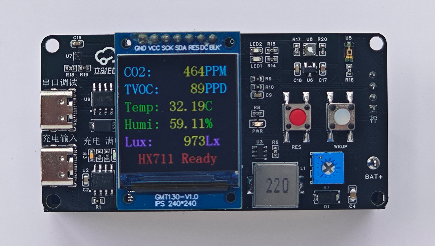
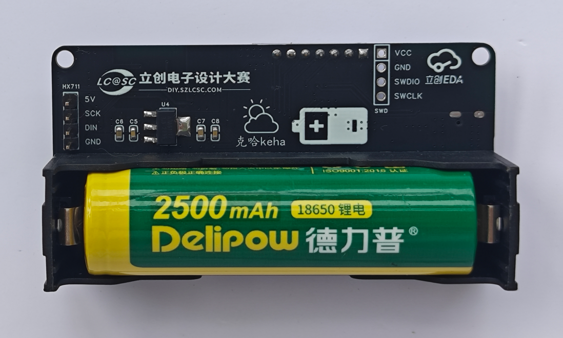
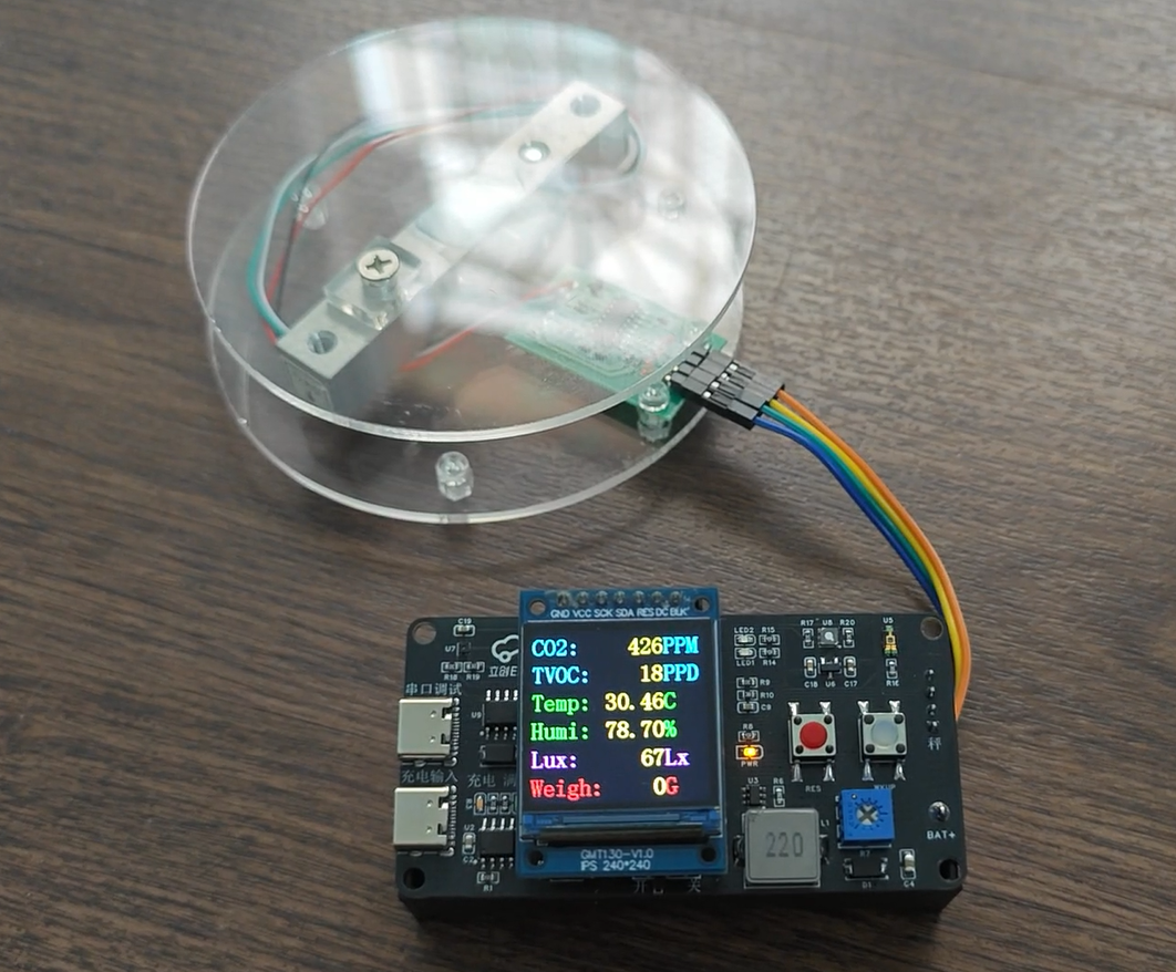
Physical product image

1. Project function introduction
(FreeRTOS real-time operating system)
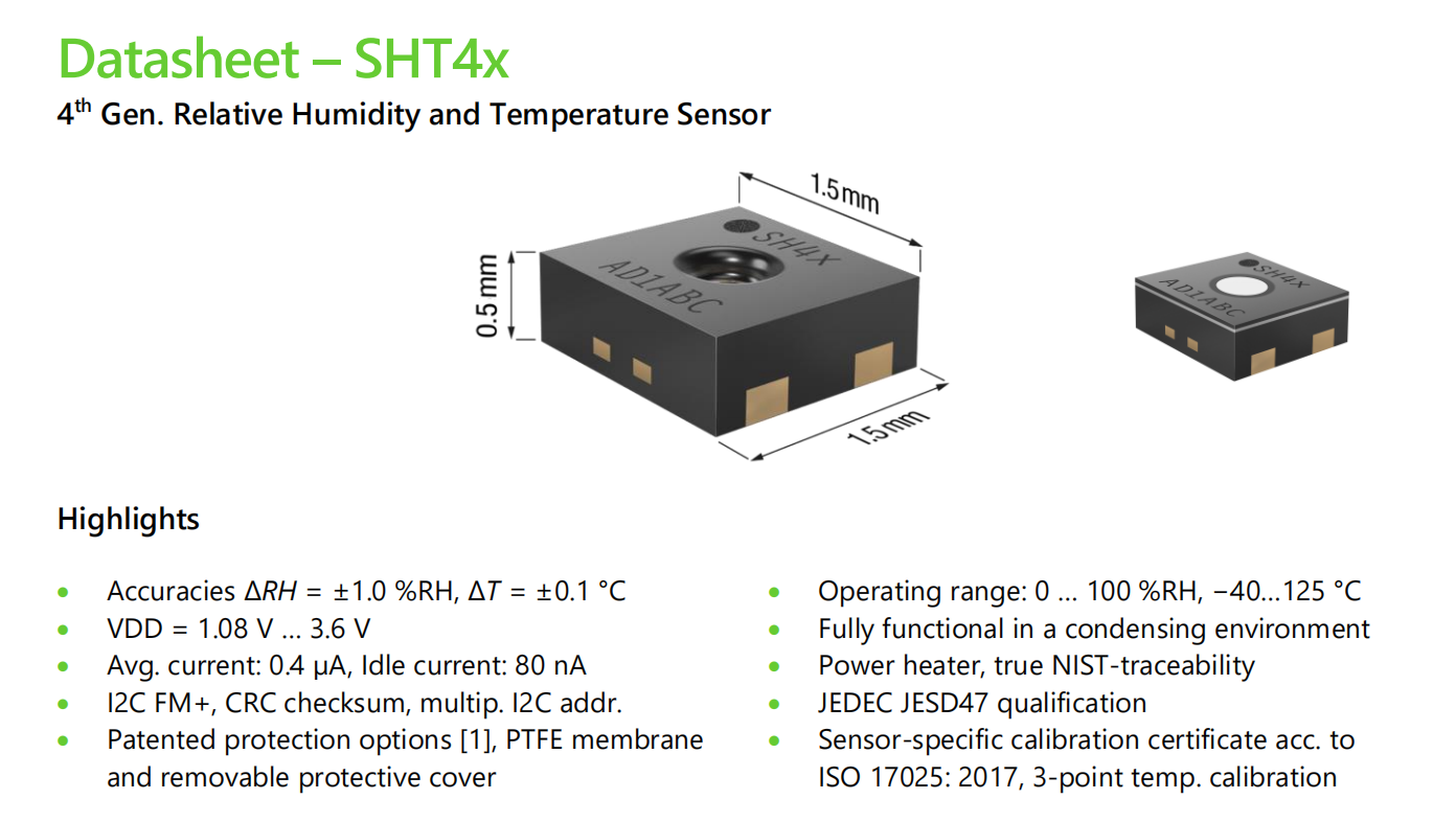
1. Temperature and humidity detection SHT40
2. Air quality detection SGP30, CO2 concentration, TVOC
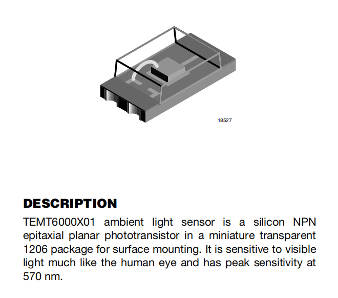
3. Light intensity detection TEMT6000, illuminance range: 1-1000 lux
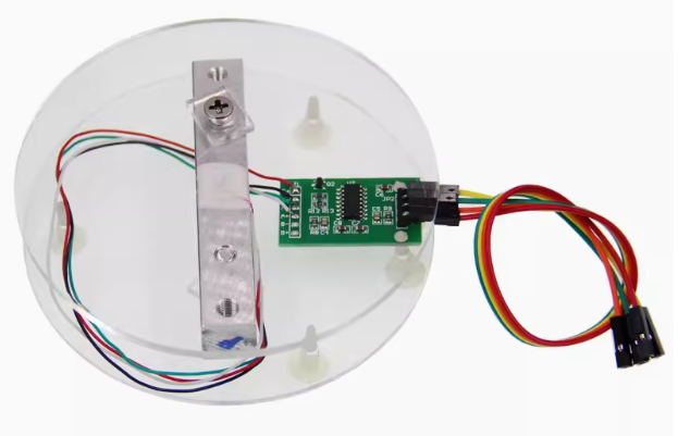
4. Electronic scale HX711, 5KG range (can use scales with other ranges)
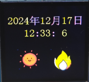
5. Clock display, the icon changes according to the set time and temperature, the time can be modified via serial port, no code modification required
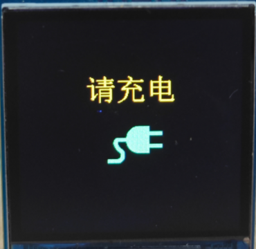
6. Battery powered with charging protection to prevent overcharging and over-discharging, and automatically controls the charging current. A charging prompt will appear when the battery is low.
Sensor detection interface: (SGP30 initialization requires some time; HX711 will continuously display "Ready" if not connected, but will not display if the interface is switched.)

Time display: Displays the time and changes images according to day/night (sun and moon, code-defined). Displays three states based on temperature: hot, cool, and cold (customizable temperature).
Battery power detection: If using battery power, a prompt will appear to charge when the battery is low.
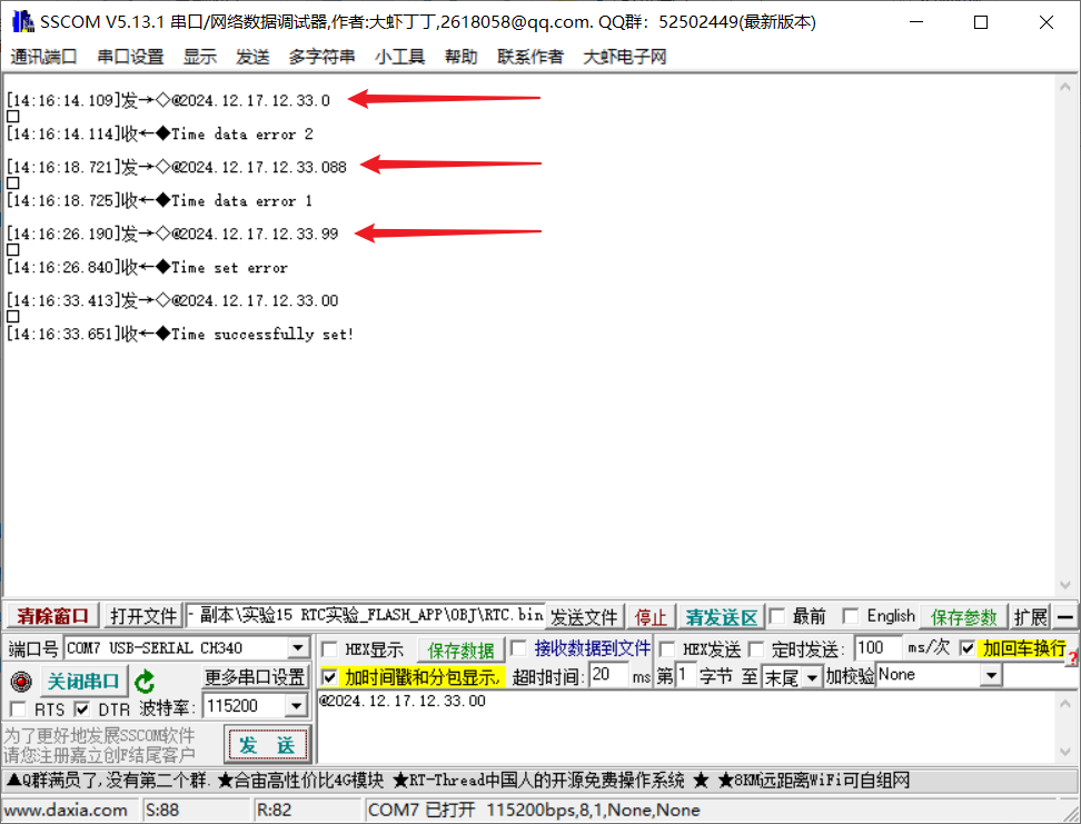
The RTC time can be changed via serial port without modifying the code. The serial data packet format is shown in the image: @2000.01.02.03.04.05.06 (with carriage return and line feed). Incorrect time format or time setting will be indicated.
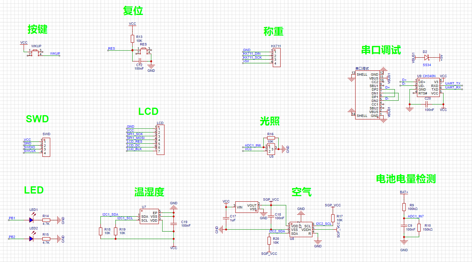
2. Hardware Section
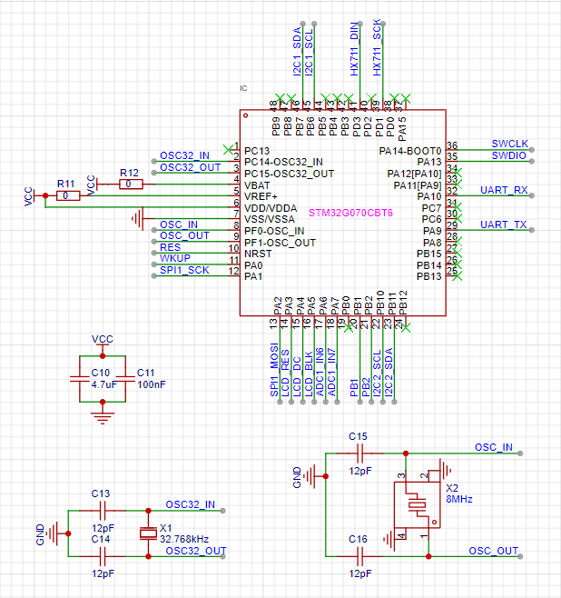
: 1. The main controller is selected as STM32G070CBT6. Originally, STM32G030C8T6 was used, but due to insufficient Flash and SDRAM for FreeRTOS and storing LCD images, it was replaced with STM32G070CBT6.
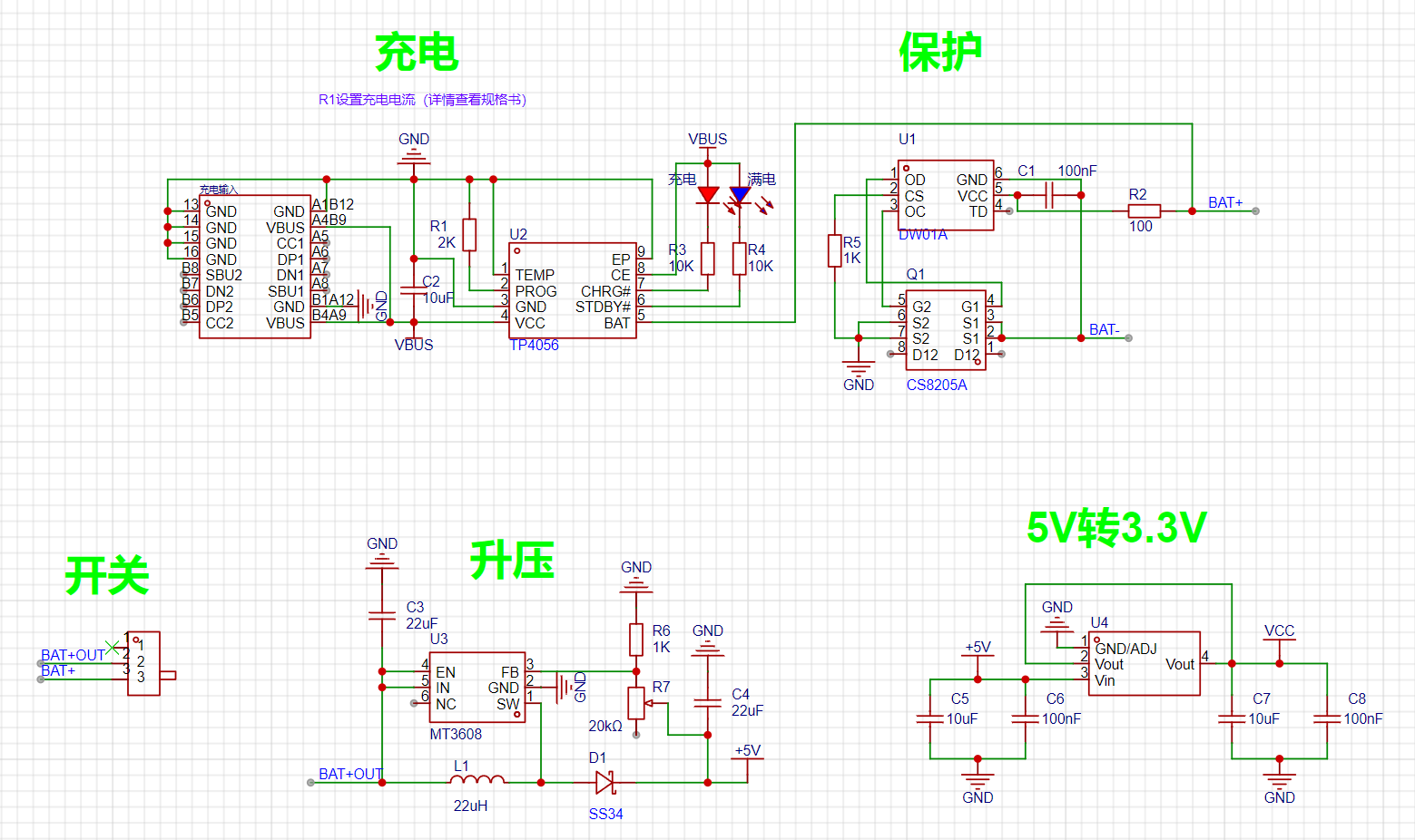
2. Power Input Section: Features charging protection to prevent overcharging and over-discharging of the battery, and automatically controls the charging current for better battery protection. Type-C female connector.
Maximum charging current: 1000mA;
Charging cut-off voltage: 4.2V;
Battery over-discharge protection voltage: 2.4V;
Maximum output current: 2A (recommended for use within 1A);
Output voltage: 4~12V (can be modified to higher output).
When the Type-C is connected to the power input terminal, the blue light illuminates and the red light flashes rapidly, indicating that power is connected. During battery charging, the red light remains on. The blue light illuminates when fully charged.
When a power source is connected to the charging input terminal, current is obtained from the power input terminal. If no power source is connected, current is obtained from the battery. The output automatically shuts off when the battery voltage drops below 2.4V.
Precautions:
When connecting the battery for the first time, there may be no voltage output. Power on the power input terminal to activate the protection circuit. When using a mobile phone charger, it must output at least 1A; otherwise, it may not charge properly.
The output voltage of this circuit is adjustable after boosting. When soldering, it is best to solder the power supply section first and adjust the boosted output voltage to 5V before soldering other circuits (adjust the output voltage to 5V after soldering other circuits, and then solder the AMS1117 3.3V last).
Pay attention to distinguishing the positive and negative terminals of the battery.
3. The serial port module for sensors and other circuits
can be used to modify the time or print debugging. The package includes a
SHT40
SGP30

TEMT6000
HX711 module + 5KG pressure sensor set, a
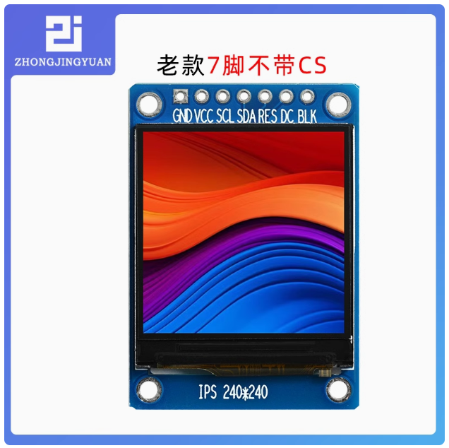
1.3-inch IPS TFT display, a 1.3-inch ST7789 IPS LCD screen, and
a single battery box. The battery box itself is a plug-in component and requires a slight modification: bend the negative pin to a surface mount.

3. The software
code has been uploaded as an attachment, with extensive and detailed comments, a basic program for beginners using FreeRTOS.
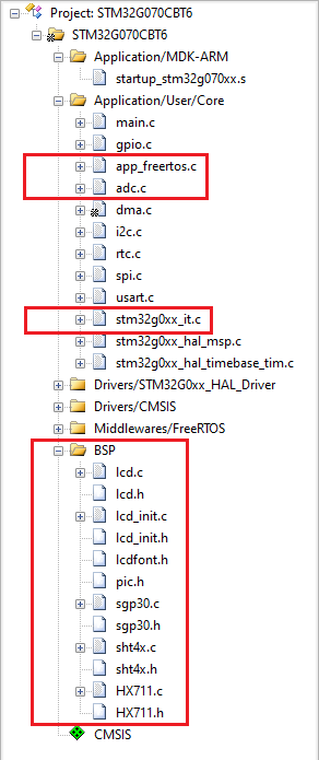
The main program is primarily located in the app_freertos.c file.
The LCD, SHT40, SGP30, and HX711 drivers are in the BSP
light intensity and battery detection ADC-related sections in the adc.c file.
Serial port data packet processing for time modification is handled in the stm32gxx_it.c file
. Task 1: Relatively low priority, temperature and humidity detection and display.

Task 2: Relatively low priority, CO2 and TVOC concentration detection and display (SGP30 requires initialization for a period after power-on).

Task 3: Relatively low priority, light intensity and battery level

detection and display (light intensity conversion is detailed in the documentation). Task 4: Relatively low priority, weighing measurement and display.

The weighing module requires calibration; see the documentation > HX711 for details.

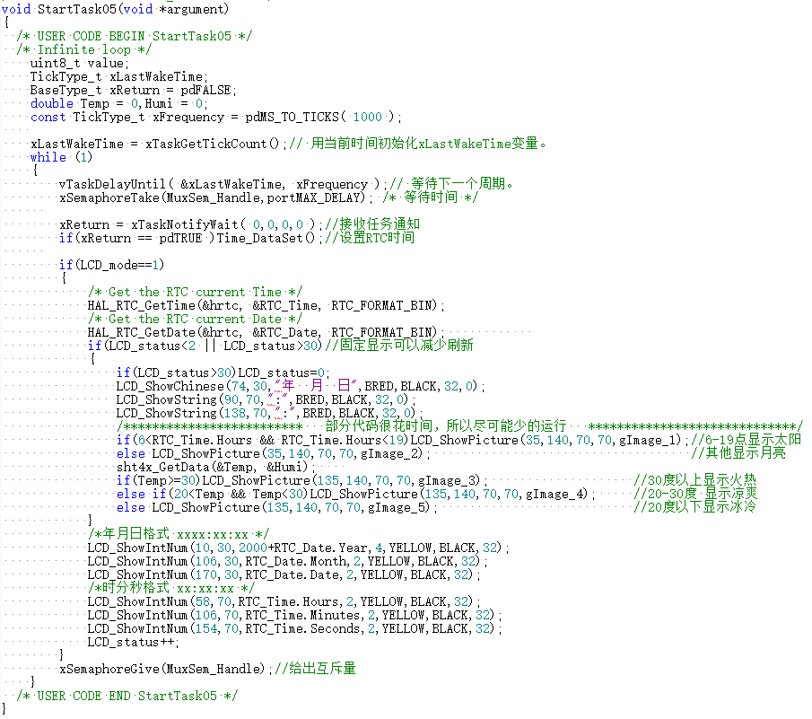
Task 5: Relatively medium priority, displaying time and updating the display time every second; the display icon changes according to time and temperature.
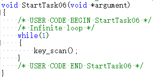
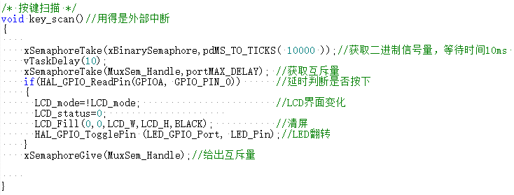
Task 6: Relatively high priority, detecting button presses (external interrupt).
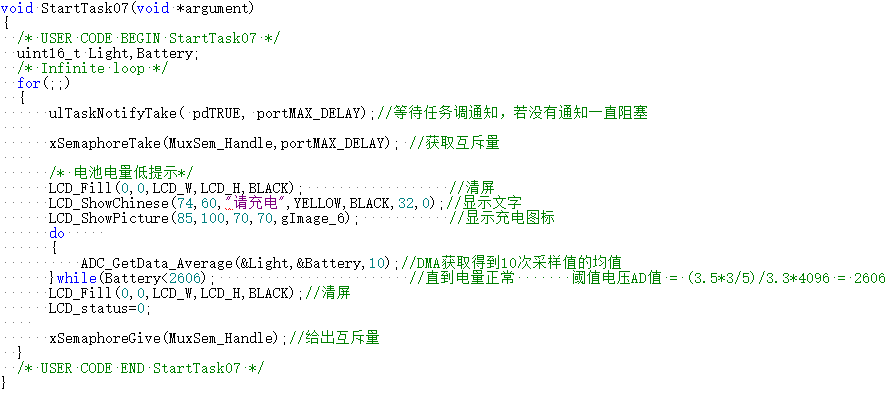
Task 7: Relatively high priority, but requires notification to execute; if low battery is detected, prompt for charging.
4. References
and Attachments


 京公网安备 11010802033920号

 2200AAG6002B3JA


