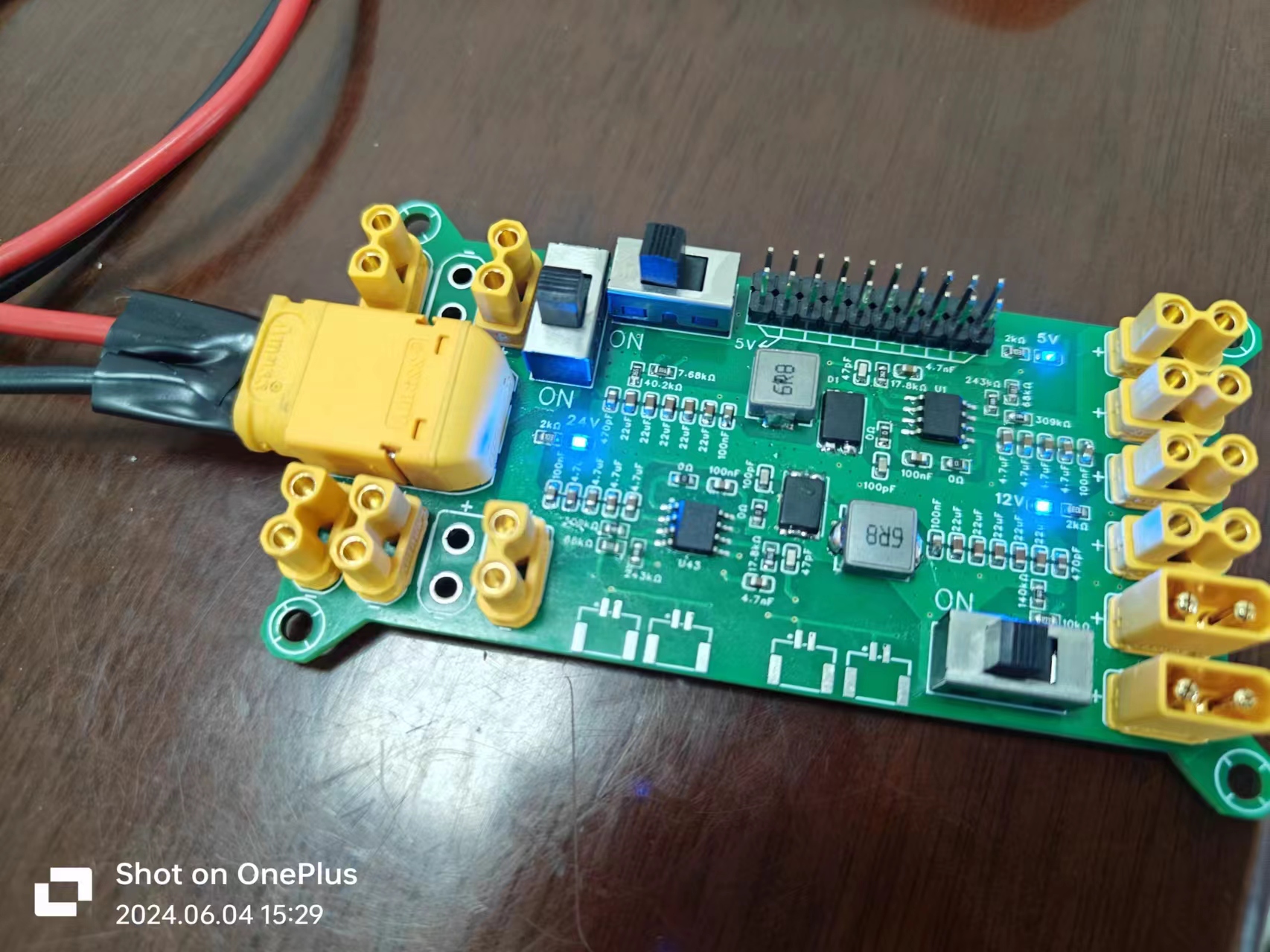
The TPS54540DDAR is used as the power supply chip. This chip has strong current carrying capacity, can handle a maximum current of 5A, and has a voltage input of 4.5V to 42V. It has advantages such as wide applicability and low power consumption. Its layout has low current loss and its current carrying capacity is relatively high compared with other power supply circuits.
20036611e9f7ed2dcec6f341aee82e2.jpg
PDF_TPS54540DDAR Power Board.zip
Altium_TPS54540DDAR power board.zip
PADS_TPS54540DDAR power board.zip
BOM_TPS54540DDAR Power Board.xlsx
93746
STC32G Communication Learning Board
This project uses the STC32G12K128 as the main control MCU to learn the three communication methods commonly used in industry: 485, CAN, and 433.
This project uses the STC32G12K128 as the main control MCU
to learn the three commonly used industrial communication methods of the STC32G: RS485, CAN, and RS433.
To effectively utilize the MCU's I/O ports, all I/O ports have been brought out, allowing it to also be used as a minimum core system board.
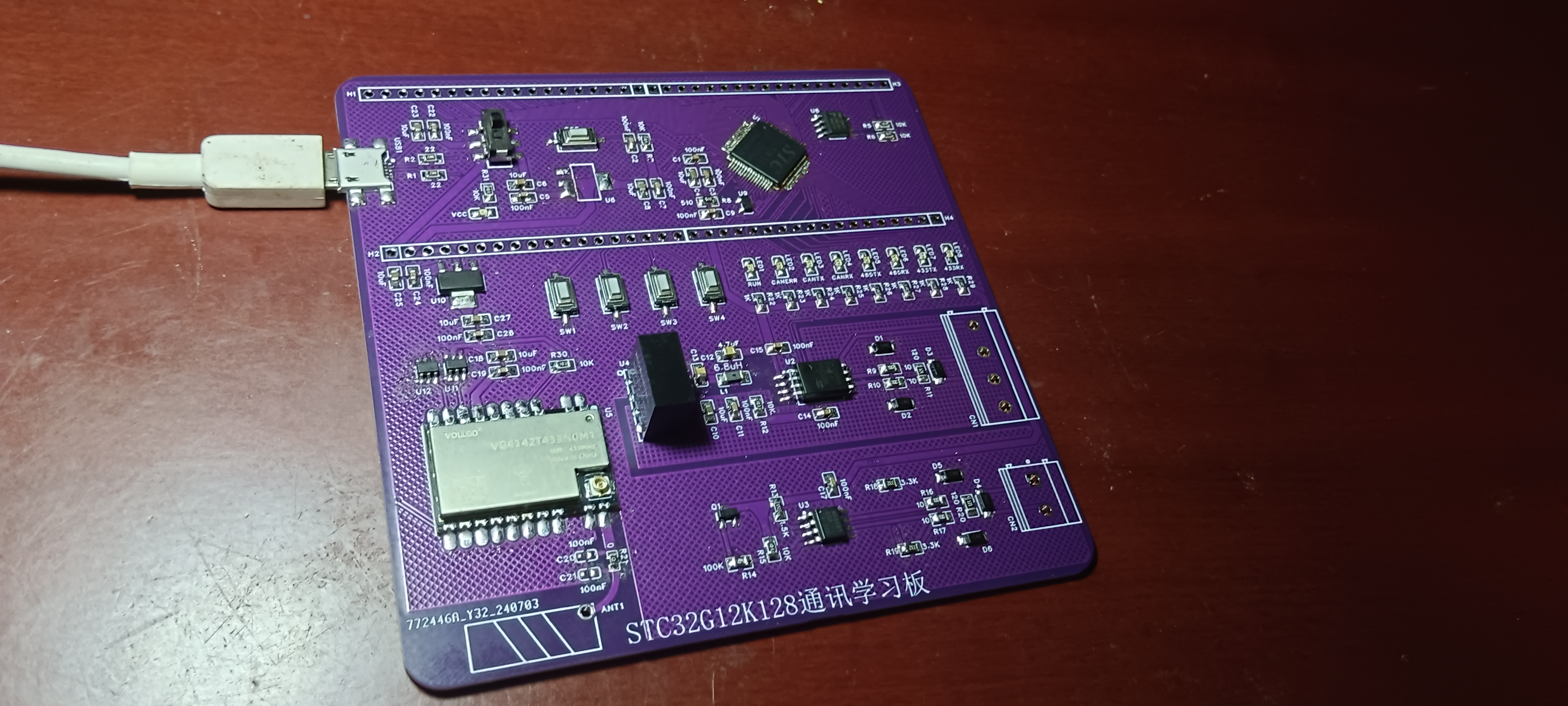
The RS485 communication uses the MAX485ESA chip;
the CAN communication uses the CA-IS3050G chip, powered by a Mornsun B0505S-1WR3 isolated power supply;
the RS433 wireless communication uses the VG4142T433N0M1 module from Wojin Technology, powered by an AMS1117-3.3.
For communication with a 5V-powered MCU, an SN74LVC1T45DBVR chip is used for level conversion.
Currently, the PCB, except for the connectors, has been soldered and LED testing has been performed (see attachment).
Further learning of each communication module will follow.
WeChat_20240715232339.mp4
PDF_STC32G Communication Learning Board.zip
Altium_STC32G Communication Learning Board.zip
PADS_STC32G Communication Learning Board.zip
BOM_STC32G Communication Learning Board.xlsx
93747
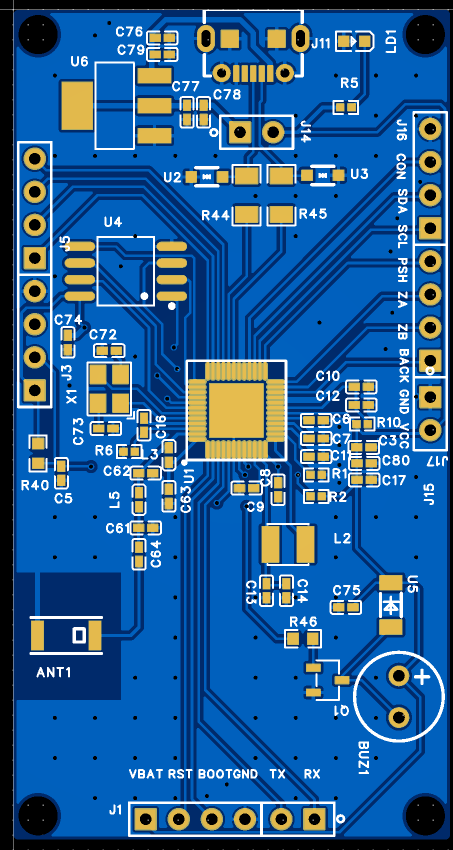
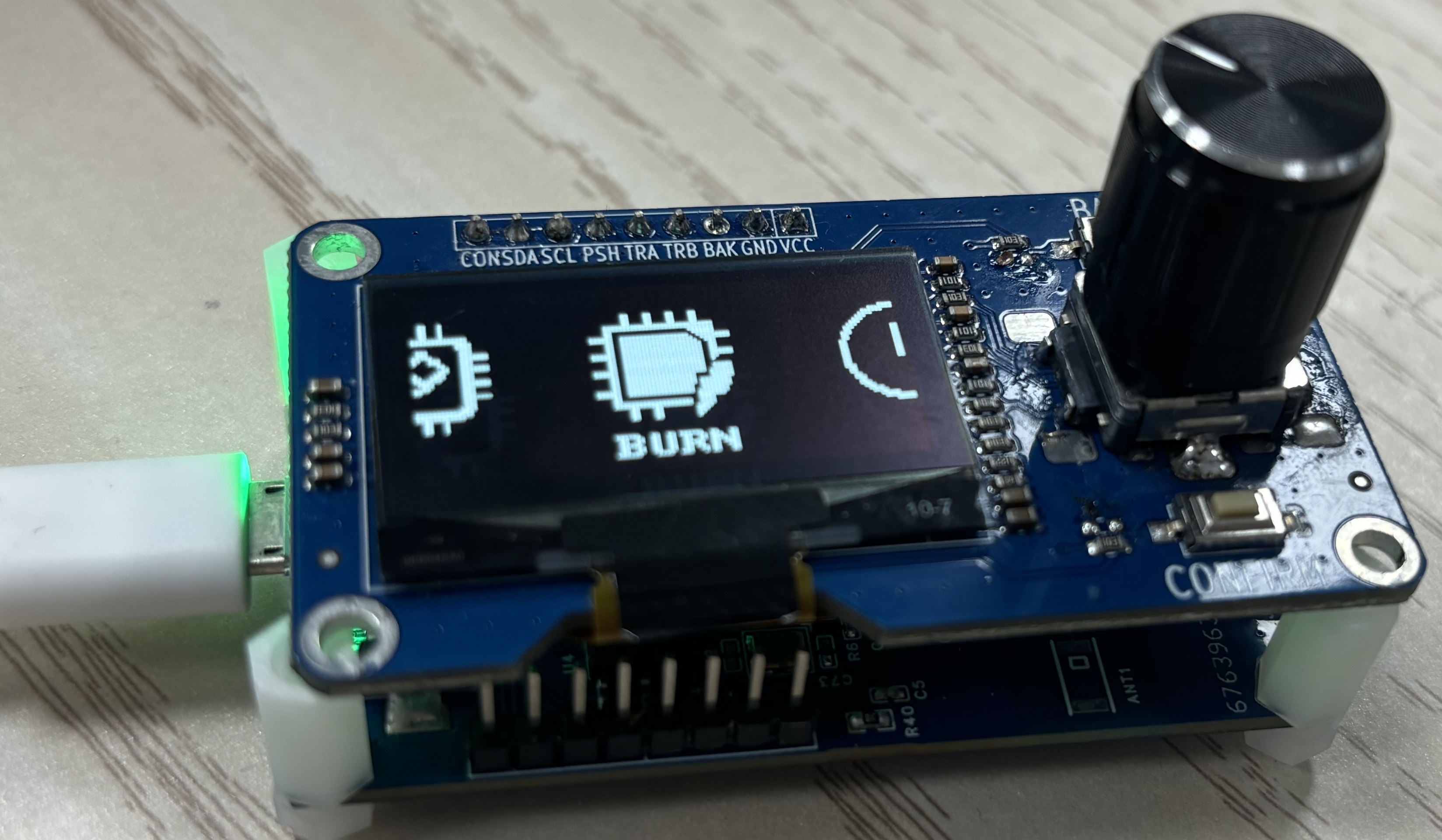
Ingchips player
What is it? It's a development board, an offline programmer, and a gadget. It connects to various peripheral functions of Inchips chips, and with your ideas, it becomes even more fun...
The schematic and PCB
layout were created using LCSC EDA Professional Edition. Software development was

performed
using Ingchips SDK + Keil 5 MDK536. The project file structure
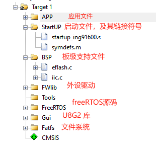
is shown in the figure.
The project consists of a top panel (OLED screen + rotary encoder + buttons) and a bottom panel (ING91682C design).
Main functions include:
1. Real-time clock display;
2. Offline programming of Ingchips series chips' built-in flash; 3. Offline
erasing of Ingchips series chips' built-in flash;
4. File management;
5. BLE FOTA upgrade.
Important considerations for
PCB layout: Ensure antenna matching is close to the chip. The DC-DC converter's ground (AVSS) should be connected to the chip's ground via a 0-ohm resistor. Inductor parameters for the DC-DC converter: The official recommendation is 4.7uH; in practice, a larger inductor results in lower ripple. Inductors from 4.7uH to 22uH are acceptable. Maximum ESR is 500mohm, and current is greater than 10mA. For DC-DC related pins: VD, VX, and DVSS, keep traces as short and close to the chip as possible.
Demo video
and other attachments can be uploaded to
the open-source code repository: https://github.com/Inchips-zb/IngDelineDownloader.git
f949314c545f55303a988aff3b20ed1e.mp4
PDF_Ingchips player.zip
Altium_Ingchips player.zip
PADS_Ingchips player.zip
BOM_Ingchips player.xlsx
93748
STC32G12K128 Minimum System Board
STC32G12K128 minimum system + CH343P serial port download circuit + hardware soft-start circuit + button control for microcontroller power supply and microcontroller reset
STC32G12K128 minimum system + CH343P serial port download circuit + hardware soft-start circuit + button control for microcontroller power supply and microcontroller reset
stc microcontroller.mp4
QQ Video 20240716034333.mp4
PDF_STC32G12K128 Minimum System Board.zip
Altium_STC32G12K128 Minimum System Board.zip
PADS_STC32G12K128 Minimum System Board.zip
BOM_STC32G12K128 Minimum System Board.xlsx
93750
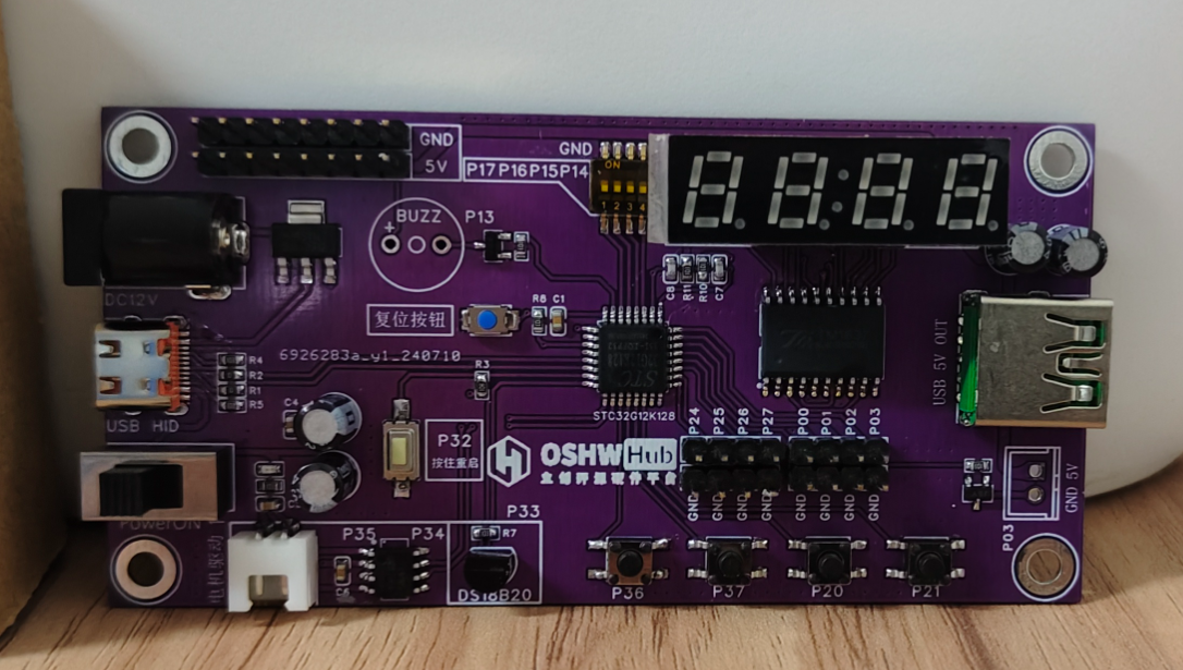
STC32G12K128 Development Board
STC32G12K128 Development Board
The development board based on the STC32G12K128 features an onboard motor driver, a four-digit clock display, a DIP switch, a buzzer, buttons, supports USB HID hardware download, and supports DC input.

PDF_STC32G12K128-Development Board.zip
Altium_STC32G12K128-Development Board.zip
PADS_STC32G12K128-Development Board.zip
BOM_STC32G12K128-Development Board.xlsx
93751
electronic


 京公网安备 11010802033920号

 45WER50KLFTB


