This project is a modified copy of the "DIY Project" based on the SL2.1A USB 2.0 hub from the "LCSC EDA Course Case Recommendation"
: https://oshwhub.com/course-examples/diy-xiang-mu-ji-yu-sl2-1a-de-usb-2-0-ji-xian-qi.
1. Principle:
This project remains unchanged; refer directly to the above link. 2.
CrystalDiskMark 8.0.4 was used to test an existing USB flash drive; the results are shown in the image.
3. Casing : The casing
consists of upper and lower shells, with a snap-fit installation. Note: Once closed, it cannot be reopened. Please ensure it functions correctly before closing. 4. PCB Installation Notes: The board thickness must be selected as 1.0. 5. Rendered image 6. Actual product image
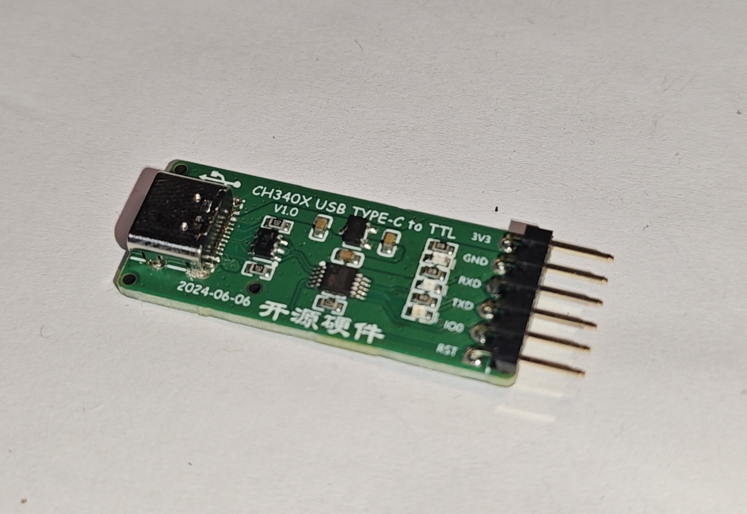
A serial port debugging tool based on CH340X, which can be used to automatically download firmware for ESP8266/ESP32.
Product Introduction:
The CH340X-USB-TYPE-C to TTL module uses the CH340X as its core, with an internal crystal oscillator and a maximum baud rate of 2Mbps. It is software-compatible with the CH341 driver, features backflow protection, and provides corresponding communication and power interfaces. The communication interface has indicator lights to show the working status, ensuring stable communication and a compact size. It is a serial port tool for automatically downloading programs to ESP8266/ESP32.
Product Features:
USB TYPE-C interface:
Full-speed USB device interface, compatible with USB V2.0.
Fully compatible with serial port applications under Windows operating systems on the computer side, requiring no modification.
Hardware full-duplex serial port with built-in transmit/receive buffers, supporting baud rates from 50bps to 2Mbps.
Built-in firmware, software compatible with CH341, allowing direct use of the CH341 VCP driver.
Driver
download address: https://www.wch.cn/downloads/CH341SER_EXE.html
Pin Function Table
:
CH340X Module Pins
ESP8266/ESP32 Pins
1
3V3
3V3
2
GND
GND
3
RXD
TXD
4
TXD
RXD
5
IO0
IO0
6
RST
EN
Product 3D Rendering Images


![]()
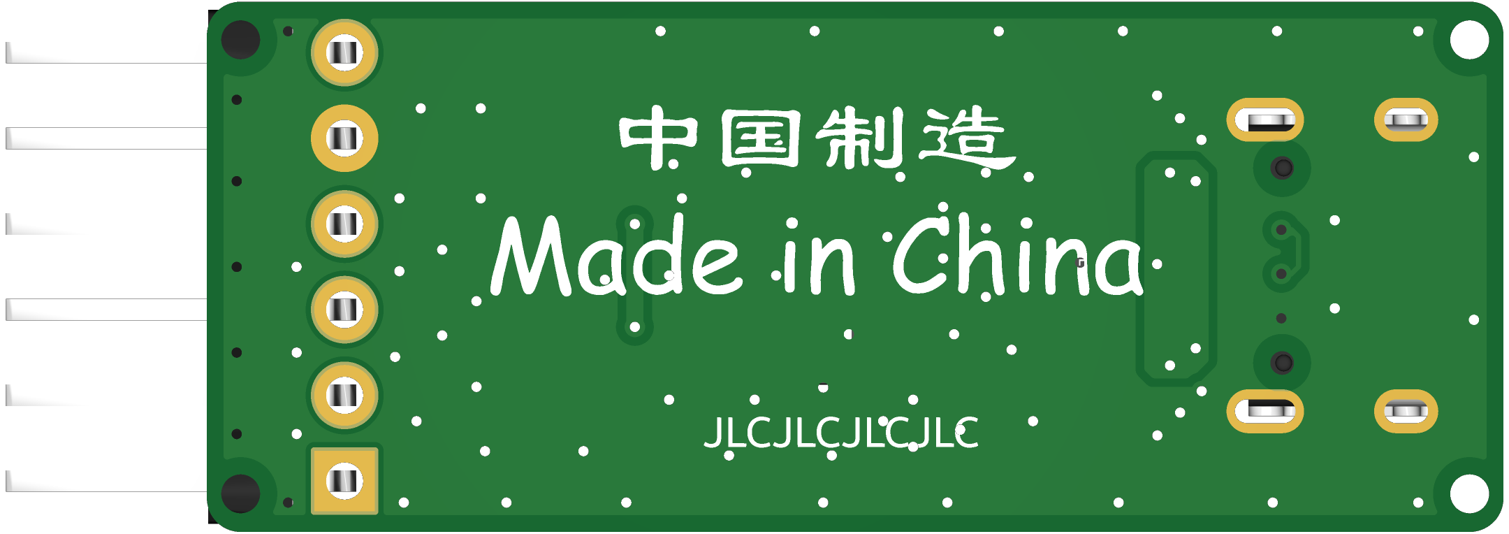
Actual Product Photos
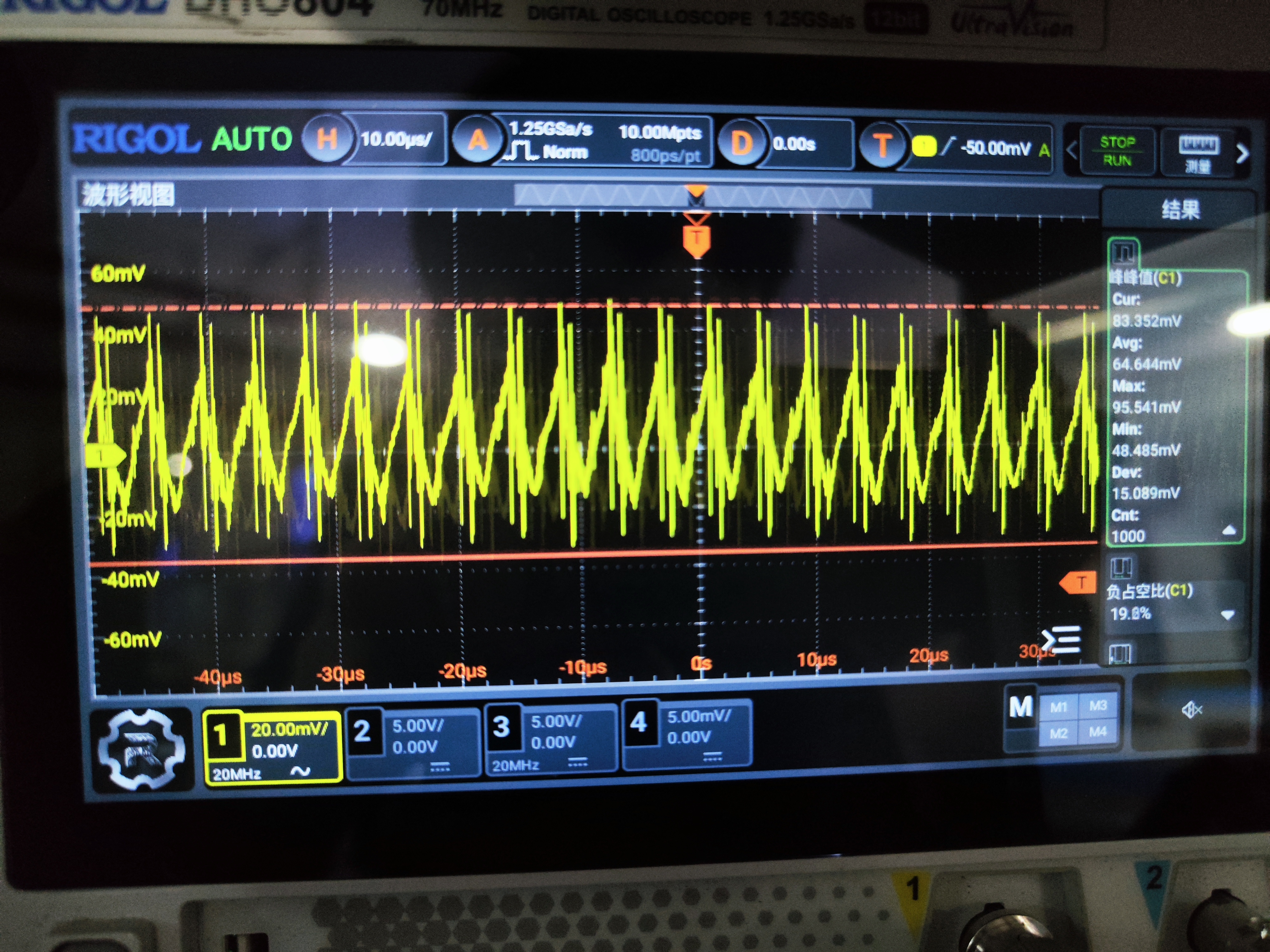
This project uses the EG1163S control chip. All parameters were calculated independently. Testing under no-heat-dissipation conditions showed a stable single-channel output of 19V 7A. After three minutes of stable operation at 7A, the highest stable temperature was observed at the MOSFETs: 53 degrees Celsius for the upper MOSFET and 48 degrees Celsius for the lower MOSFET. The measured ripple under a 7A load was 83.5mV.
This project is the first version of the gimbal power supply, designed for continuous 6*2A load operation 24/7 on a DJI battery.
It boasts extremely high cost-effectiveness, extremely high power density, relatively comprehensive protection, and no need for additional cooling. However,
it has drawbacks such as relatively high voltage ripple (83mV at full load), still relatively high heat generation (not tested under 24/7 full load), and a fixed output of only 19V.
Advantages:
High cost-effectiveness: Using free prototyping from LCSC, the component price (excluding XT30) is only around 14 RMB.
High power density: The board size is only 4.7*4.7cm, providing 19V 7A*2 (still being optimized, replacing MOSFETs, reducing gate resistance, etc.).
Protection measures: Using 5*6 packaged PMOS for reverse connection protection, high-side current sensing, setting output current thresholds, and EN undervoltage lockout to protect the battery.
Disadvantages:
Ripple does not meet requirements (below 100mV at full load), heat generation reaches 85 degrees Celsius, unsuitable for long-term stable operation. Gate rise time is too long, resulting in weak chip driving capability.
Improvement directions:
1. Use MOSFETs with smaller QG. The CSD18540 is used in this case, with a QG of 42nc, which is insufficient for driving the EG1163.
2. Connect a DAC interface to the feedback terminal for easy voltage adjustment.
3. Implement voltage and current detection at the output terminal for convenient microcontroller closed-loop control. 4.
Optimize the layout with larger openings to enhance heat dissipation.
5. Install electrostatic discharge (ESD) and TVS devices to ensure operational stability.
Note: The part number (MMB) is not entirely accurate; for example, the inductor value is 15uH. If copying, please carefully verify the information.
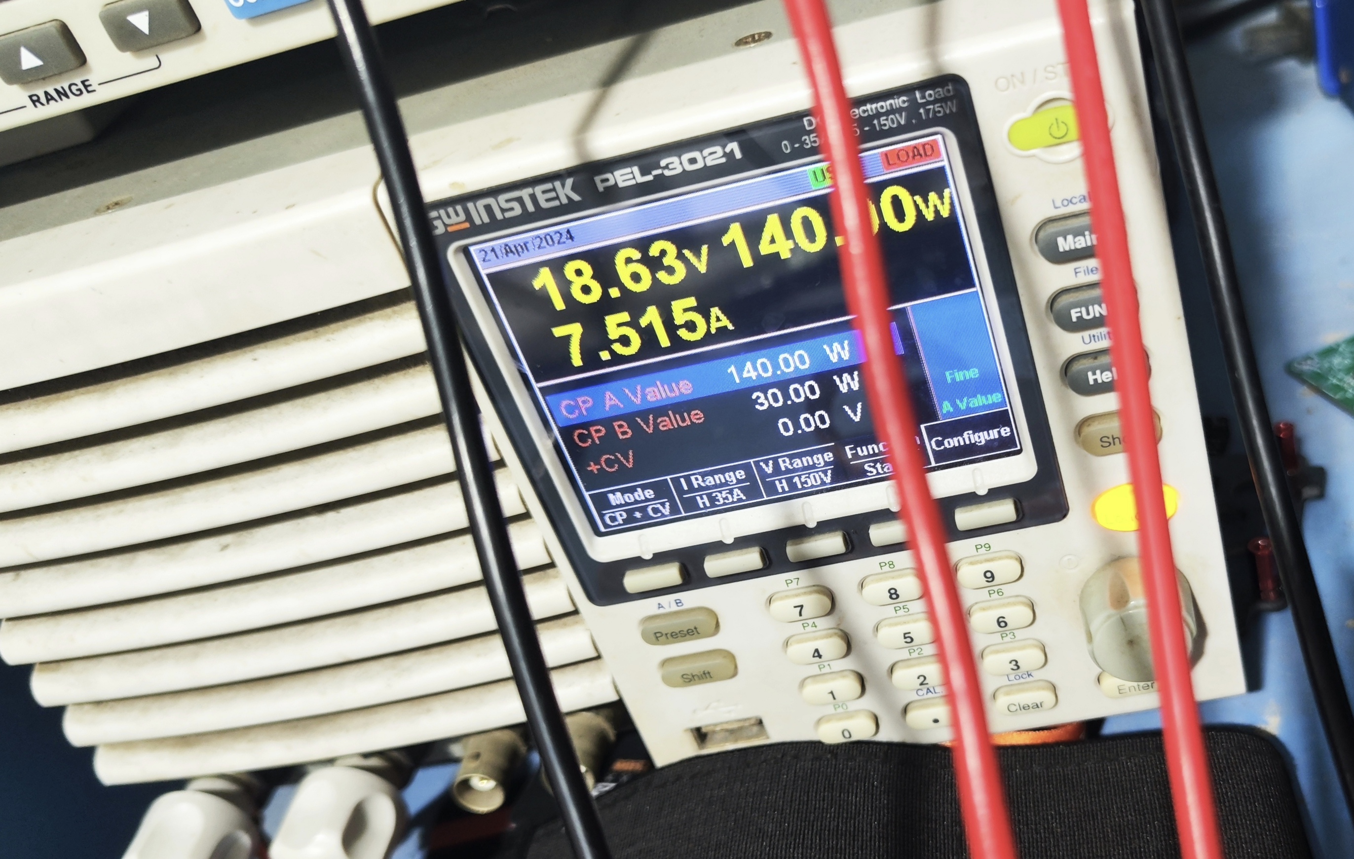
Efficiency: Input 146W, Output 140W (including line loss), efficiency 96%.
Update 1: After replacing the CSD18540 with an NTMS4C06N, the single-channel continuous load capacity without heat dissipation reaches 19V 8.9A. The gate resistor is 6.8Ω.
Below are test images.
Update 2: Previously, the ripple measurement did not have the 20M bandwidth limit enabled. After enabling it, the ripple measured at a 7A load was 83.5mV, meeting the usage requirements.
Update 3: Upgraded to a four-layer board, obtaining a complete ground plane!!!
7.5A temperature measurement


PDF_Dual-channel small-size fixed-output DC-DC step-down module based on EG1163S.zip
Altium-based EG1163S dual-channel small-size fixed-output DC-DC step-down module.
PADS_Dual-channel small-size fixed-output DC-DC step-down module based on EG1163S.zip
BOM_Dual-channel small-size fixed-output DC-DC step-down module based on EG1163S.xlsx
93763
STC32 core board
Core board based on STC32G12K128K
Based on the STC32 minimum system design, all pins are brought out

using the Nanjing Qinheng CH340N USB-to-serial chip, and serial programming is performed directly using Type-C.
PDF_STC32 core board.zip
Altium_STC32 core board.zip
PADS_STC32 core board.zip
BOM_STC32 Core Board.xlsx
93764
electronic
 3. Casing : The casing
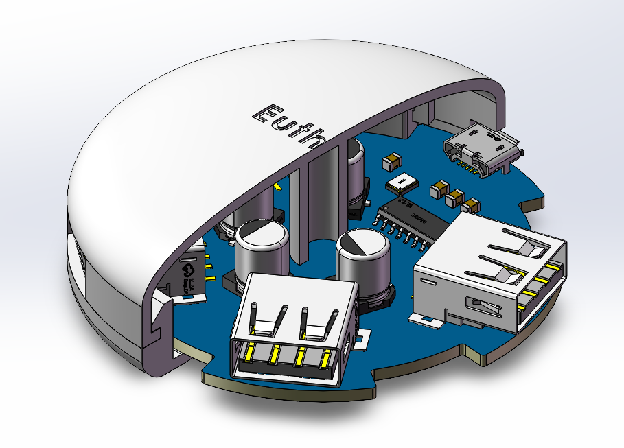


 京公网安备 11010802033920号

 0522660011


