Writing code should definitely start with lighting up LEDs! This development board includes standard LEDs and an 8x8 programmable WS2812B.

WeChat_20240711160338.mp4
PDF_LED Lighting Development Board Based on STC8H8K64U.zip
Altium-based LED development board (based on STC8H8K64U).zip
PADS_LED Development Board Based on STC8H8K64U.zip
BOM_LED Lighting Development Board Based on STC8H8K64U.xlsx
93825
#Training Camp# A Simple Digital Oscilloscope Based on STM32
A simple digital oscilloscope based on STM32, designed and implemented using the B-side EDA video BV1py421i76N, without modifications.
A digital oscilloscope is an instrument used to display electrical signal waveforms. It mainly consists of analog front-end processing circuits, microcontroller circuits, power supply circuits, control circuits, trigger circuits, and calibration circuits.
This project presents a simple STM32-based oscilloscope for detecting and displaying waveforms. It features an adjustable PWM square wave output with adjustable frequency and duty cycle, powered via Type-C.
The input signal amplitude can be measured from -1.6V to 5V and from -80V to 250V by adjusting the switch. When the input signal amplitude is small, the lower voltage range should be selected first. If the input signal amplitude is uncertain, the higher voltage range can be used first. If it falls within the lower voltage range, the lower voltage range can be used for more accurate measurement results, while also protecting the circuitry.
An additional PWM signal is used to simulate a simple function generator, allowing the output of a simple square wave signal by changing the frequency and duty cycle of the output PWM.
Engineering design source:
202: Simple Digital Oscilloscope Project Document (yuque.com)
【LCSC GD32E230C8T6】Simple Digital Oscilloscope Design - Feishu Cloud Document (feishu.cn)
The core board supports LCSC's GD32 small board and STM32F103 small blue board, but the programs used are different.
fa7bfd2e8db76aeb4ff5fe621144c80.jpg
Simple Oscilloscope Program (STM32 Version).zip
PDF_#Training Camp# Simple Digital Oscilloscope Based on STM32.zip
Altium_#Training Camp# Simple Digital Oscilloscope Based on STM32.zip
PADS_#Training Camp# Simple Digital Oscilloscope Based on STM32.zip
BOM_#Training Camp# Simple Digital Oscilloscope Based on STM32.xlsx
93826
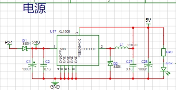
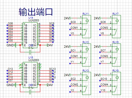
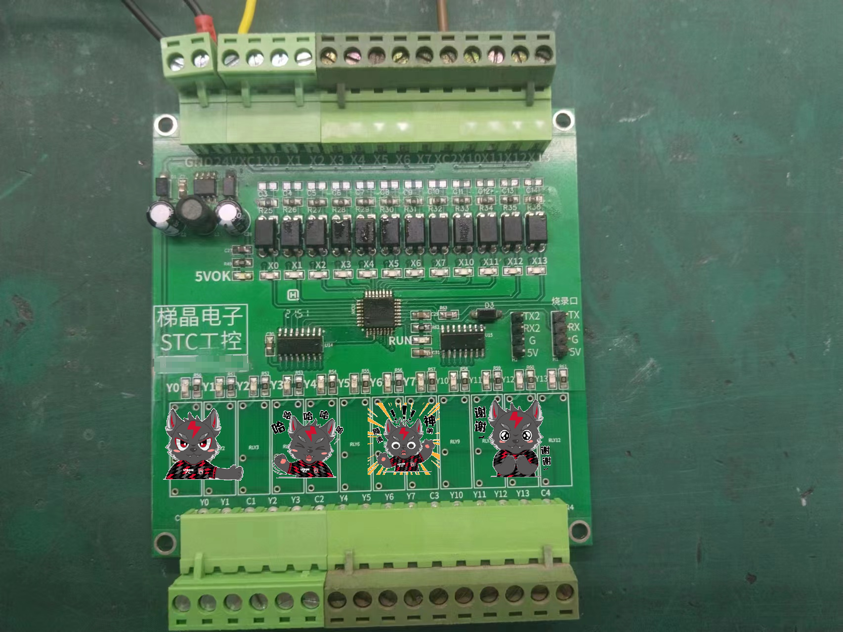
Industrial control board design based on STC microcontroller
An industrial control board based on the STC32 microcontroller was designed.
It is compatible with both STC8 and STC32 chips.
The project design includes 12 input ports and 12 output ports, which can replace a PLC to implement simple input/output port functions.
video.mp4
PDF_Industrial Control Board Design Based on STC Microcontroller.zip
Altium-based industrial control board design using STC microcontroller.zip
PADS_Industrial Control Board Design Based on STC Microcontroller.zip
BOM_Industrial Control Board Design Based on STC Microcontroller.xlsx
93827
JLCPCB Temperature and Humidity Training Camp - SHT40
I made two versions: one with an ESP8266 + OLED display and the other with an ESP32 as the main controller and an ILI9341 touchscreen as the display. I will design the casing later. The cover features the ESP8266 + OLED 0.96 version. Other versions haven't been made yet.
I made two versions: one uses an ESP8266 + OLED, and the other uses an ESP32 as the main controller and an ILI9341 touchscreen as the display.
firmware.bin
PDF_JALCIC Temperature and Humidity Training Camp - SHT40.zip
Altium_JALCSC Temperature and Humidity Training Camp - SHT40.zip
PADS_JALCSC Temperature and Humidity Training Camp - SHT40.zip
BOM_JALCIC Temperature and Humidity Training Camp - SHT40.xlsx
93828
IP2326_2S_3S Charging Manager
A lithium battery charging manager based on IP2326 with selectable 2S-3S charging and a selectable charging current of 0.5-1.5A.
Description:
This is a lithium battery charging manager based on IP2326. The maximum charging power is 12W for 2 seconds and 15W for 3 seconds.
The input is USB_C. For maximum charging efficiency, it is recommended to use a QC-compatible charger. IP2326 can request fast charging voltage from the input via DP/DM based on the current battery voltage.
The output uses an HX 2.54-4P connector, consisting of battery +, battery -, and an NTC resistor (optional).

Instructions for use:
1. Before powering on, set the number of battery cells (****Important****) and the charging current. DIP switches 1 and 2 are used to set the charging current: both 0, 0.5A; one 1, 1A; both 1, 1.5A. DIP switch 3 is used to set the number of battery cells: 0 for 2 seconds, 1 for 3 seconds.
2. If using an NTC charger, attach the NTC to the battery, connect the battery, and then connect the USB_C input.
3. During charging, the CHG indicator light will illuminate. If the battery voltage is too low, the CC indicator light will not illuminate, indicating trickle charging. Once a certain voltage is reached, the CC indicator light will illuminate, indicating constant current charging. The charging current will be the current set above.
4. The CHG indicator light will turn off when fully charged. The CHG indicator light will flash when an abnormality is detected.
5. Charging output will automatically shut off if the charging time exceeds 12 hours.


Soldering Instructions:
1. Do not solder anything marked NC on the board.
2. Use an RNTC=100K thermistor (B=4100) for the NTC resistor. Simultaneously, solder an 82K parallel resistor onto the TBD resistor. C12 can be 1-100nF or omitted.
3. If not using an NTC resistor, solder a 51K resistor onto the TBD resistor; otherwise, malfunction will occur.
4. For beginners, it is recommended to solder the IP2326 and USB first, then other resistors and capacitors, then the inductor, and finally the DIP switch and output socket.
5. The 2.54mm header pins are mainly for convenient MCU monitoring of input and output voltages, NTC temperature, and charging indicators when out in use. If not needed, soldering is unnecessary and will not affect operation.
Additional note:
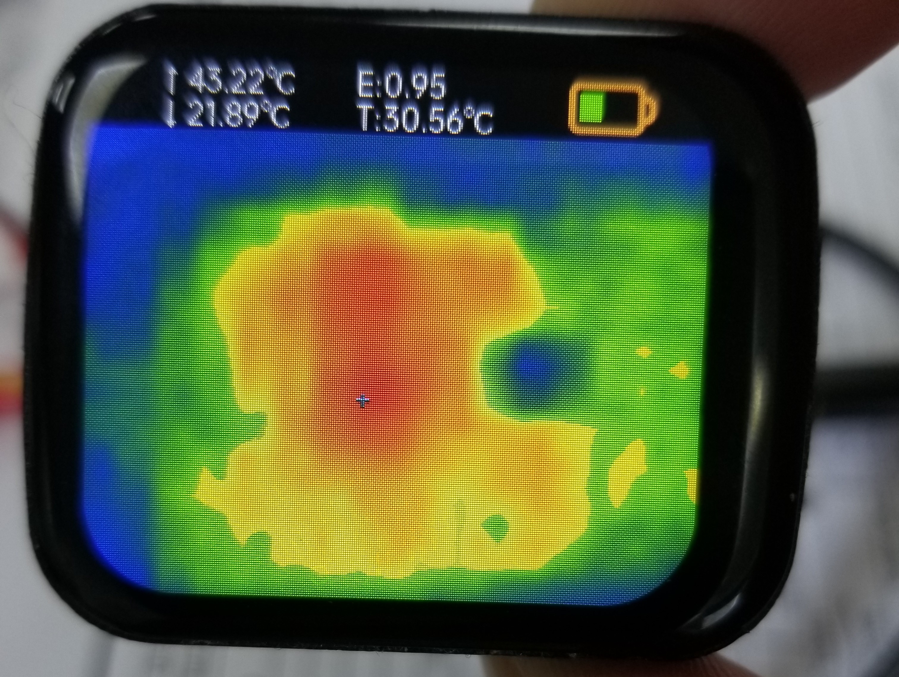
Actual measured charging current at 1A resulted in a maximum chip temperature of approximately 43 degrees Celsius – quite cool!
Precautions:
**************For safety, lithium battery charging must be supervised! ****************
**************Do not charge the battery unattended! ****************
PDF_IP2326_2S_3S Charging Manager.zip
Altium_IP2326_2S_3S Charging Manager.zip
PADS_IP2326_2S_3S Charging Manager.zip
BOM_IP2326_2S_3S Charging Manager.xlsx
93829
USB expansion dock
The project uses SL2.1A as a USB extension, combined with RTL8152B-VB-CG Ethernet chip and RTL8188EUS chip for WIFI.
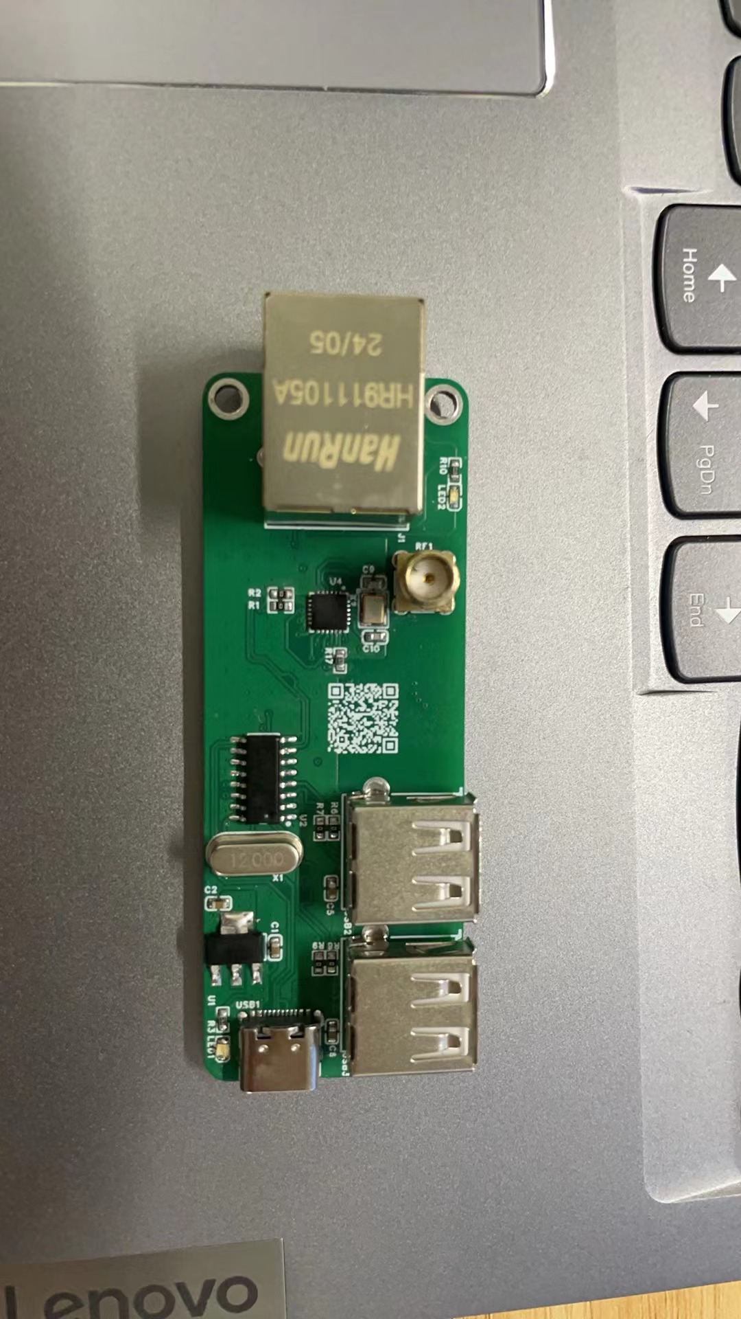
1. Project Description:
This project uses the SL2.1A as a USB expansion port, combined with the RTL8152B-VB-CG Ethernet chip and the RTL8188EUS chip for Wi-Fi.
2. Project Features:
Supports USB 2.0 expansion from 1 to 2;
supports driverless expansion;
supports 100Mbps Ethernet ports;
includes a built-in Wi-Fi port;
driverless operation under Linux, Windows, and Mac.
PDF_USB Dock.zip
Altium_USB Dock.zip
PADS_USB Dock.zip
BOM_USB Dock.xlsx
93830
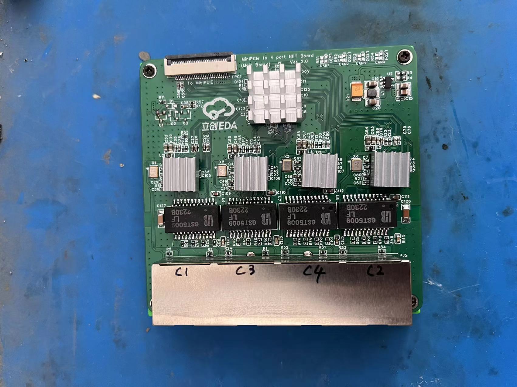
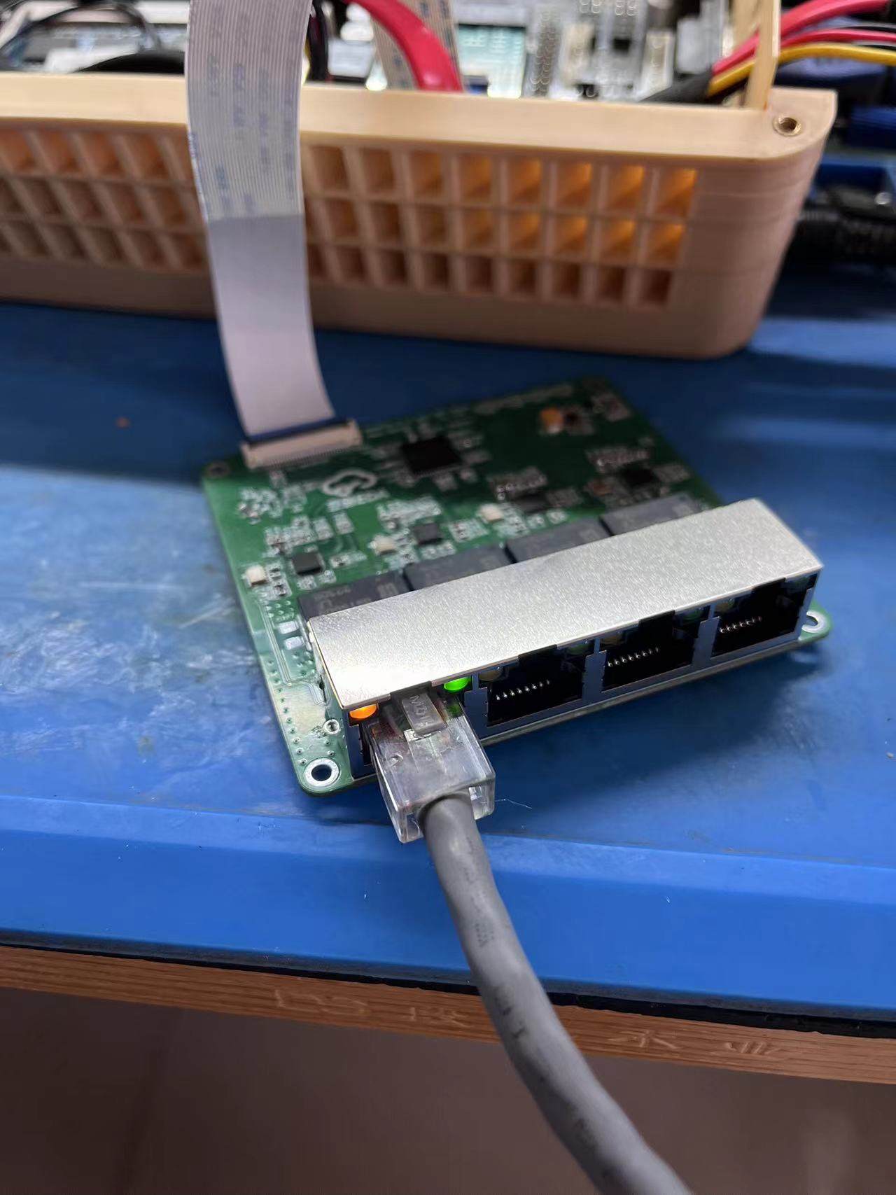
miniPCIe external quad-port network card
miniPCIe adapter for RTL8111H quad-port network card
Related post: https://www.mydigit.cn/thread-462093-1-1.html
Modifications compared to the original PCB design:
1. The miniPCIe adapter board's gold fingers were changed, with the orientation reversed. This should eliminate motherboard compatibility issues, but it hasn't been verified through PCB fabrication.
2. The 3.3V main power supply and 3.3V AUX switching circuit were modified, but this hasn't been verified through PCB fabrication either.
If the wake-on-LAN function is not needed, the wake-on-LAN circuit can be omitted; simply short-circuit the DIR resistor or install a 0-ohm resistor.
(Because this is for software router use, the wake-on-LAN function has also not been verified; you can verify it yourself if needed.)

PDF_miniPCIE External Quad-Port Network Card.zip
Altium_miniPCIE external quad-port network card.zip
PADS_miniPCIE external quad-port network card.zip
93831
Lunar Equatorial Mount
The Lunar Equatorial Mount is a super cost-effective single-axis equatorial mount. It uses an ESP8266 as the main controller and an A4988 module as the driver. It features equatorial mount mode, time-delay mode, and star-sky time-delay mode, and offers three tracking speeds: stellar speed, lunar speed, and solar speed.
July 10, 2024 – v2.0: Almost completely refactored the firmware, changed to screen display parameters, added a wireless shutter release receiver, and can be controlled by my open-source shutter release cable. July
24, 2023 – v1.1: Adopts 16P Type-C, supports QC protocol.
The Moonflower Equatorial Mount is a single-axis equatorial mount inspired by the prototype equatorial mount posted by Blacklight on Tieba and the NanoLight open-source equatorial mounts (1, 2). This equatorial mount uses ESP8266 as the main controller and A4988 module as the driver. The firmware is built using ESPHome. It has a 0.96-inch screen and dial buttons, allows for completely offline parameter adjustment, and is compatible with shutter release cable systems. Only a 2.5mm to 2.5mm cable is needed to connect various shutter release cables (at least my Stande shutter release cable works). The experience is even better when used with my own designed wireless shutter release cable. It features equatorial mount mode, time-lapse mode, and star-sky time-lapse mode, with three tracking speeds: stellar speed, lunar speed, and solar speed. The time-lapse and star-sky time-lapse modes require a shutter
release cable to function. The Type-C power input uses the PD/QC 9V protocol and can be directly powered by a power bank with PD/QC 9V support. [Note: 5V can also power the stepper motor, but it's prone to losing steps at the highest speed; it works perfectly in 1x equatorial mount mode.]
Since I lack the ability to design a 3D-printed shell, the shell uses a combination of basswood board and an acrylic protective cover. 3D-printed shell designs are welcome.
Other detailed information and precautions can be found in the attached PDF. The attachment also includes the firmware source code (.yaml), my self-compiled firmware (.bin), and the acrylic shell file (.cdr) designed using CDR.
The following are sample photos taken using this equatorial mount:

In version 1.0, a single shot with a 50mm lens took 30 seconds; I wasn't quite familiar with polar alignment yet.
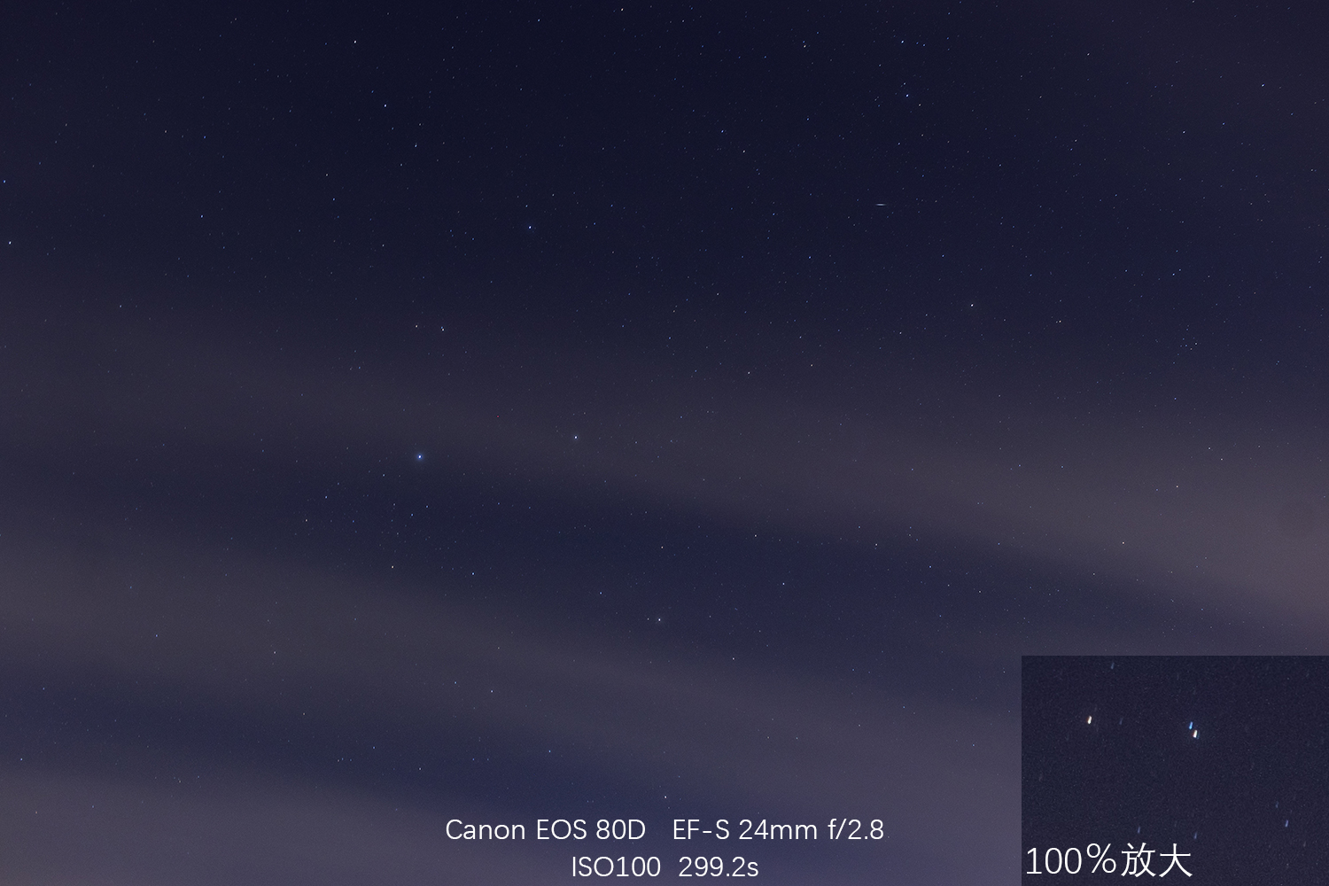
Version 2.0, a rougher test of polar alignment, took 5 minutes per shot.
Lunar Equatorial Mount.pdf
equatorial-telescope.bin
equatorial-telescope.yaml
Acrylic protective case.cdr
PDF_Lunar Equatorial Mount.zip
Altium_Moonlight Equatorial Mount.zip
PADS_Moonlight Equatorial Mount.zip
BOM_Moonlight Equatorial Mount.xlsx
93832
Moonlight Wireless Shutter Cable
Possibly the most expandable and versatile wireless shutter release cable in the world.
July 10, 2024 – Equatorial mount open sourced. June
26, 2024 – Suddenly remembered I forgot to draw the RC02 battery pads. (
June 24, 2024 – Fixed a firmware bug: the zeroing interval would be cleared to 0.
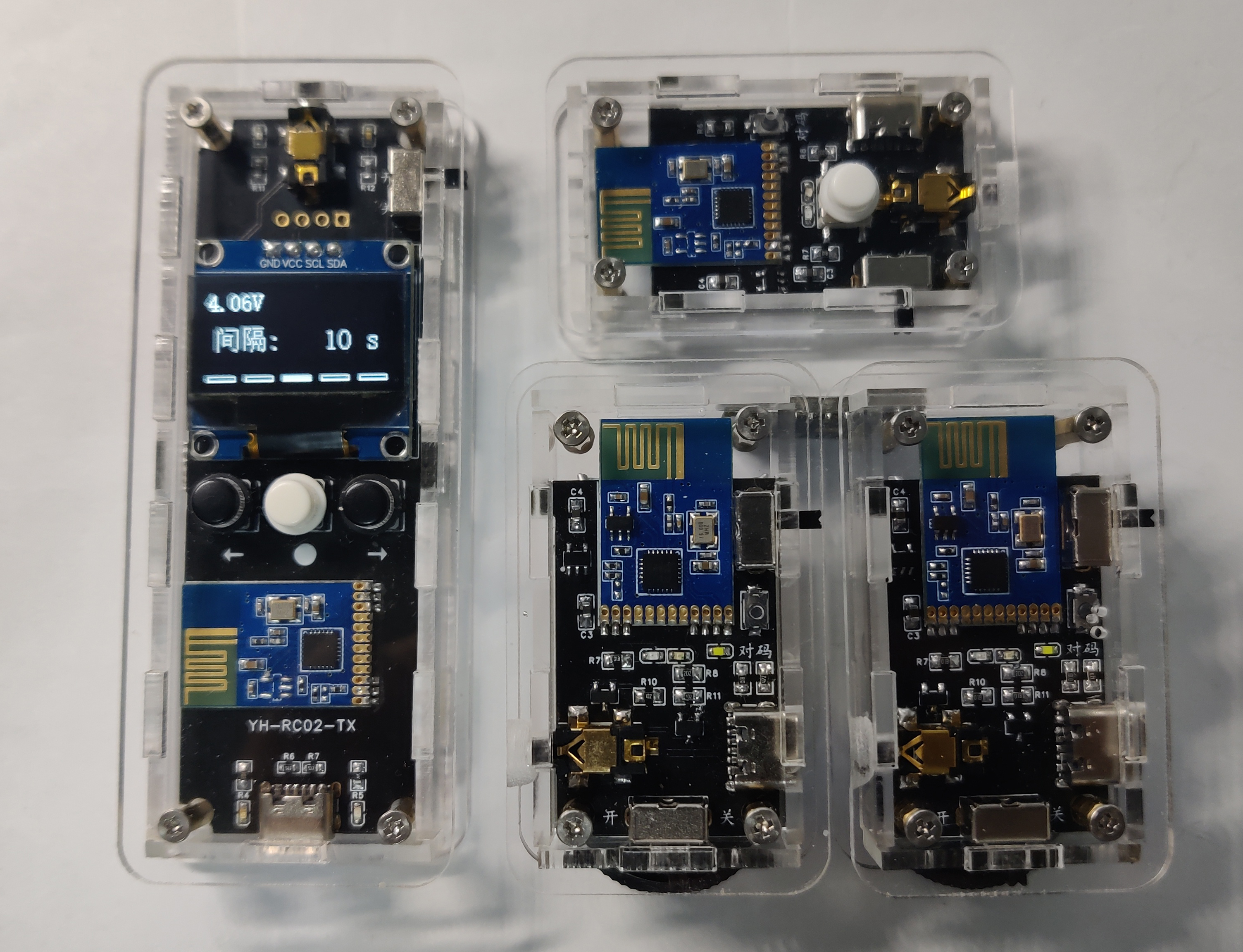
) Because there are no wireless shutter release cables on the market that meet my requirements (cheap, easy to use, and highly mobile), and because I didn't want to have too many cables for the already completed equatorial mount and the upcoming electronically controlled slider, this project was born. This complete shutter release cable has three models: RC01-TX, RC01-RX, and RC02-TX, corresponding to the simplified transmitter, receiver, and intelligent transmitter, respectively. The wireless module uses a commercially available 2.4G switch module, which has the advantage of extremely simple pairing, allowing for quick pairing and multiple combinations such as one-to-one, n-to-one, and one-to-n. The intelligent version uses the ESP8266 as its main controller, and the firmware... Built with ESPHome, it features a 0.96-inch screen and buttons, allowing for completely offline parameter adjustment. The output interface uses a common three-segment 2.5mm audio jack, without any special features.
Currently, other peripherals that can be wirelessly controlled from the transmitter include: a lunar equatorial mount. Other devices are to be added later. (
Since I lack the ability to design 3D-printed shells, the shell is made of cut acrylic; 3D-printed shells are welcome for those with the capability.
Attachments include: a documentation file and an acrylic shell designed using CDR, an ESPHome configuration file (yaml), and compiled firmware (bin). Serial log printing is not enabled by default.
Additionally, the shutter release cable offers a variety of combination options.)

Shutter release cable housing.cdr
User Manual.pdf
shutter-cable.yaml
shutter-cable.bin
PDF_Moonlight Wireless Shutter Cable.zip
Altium_Moonlight Wireless Shutter Cable.zip
PADS_Moonflower Wireless Shutter Cable.zip
BOM_月华Wireless Shutter Cable.xlsx
93833
Wireless knob
Surface Dial Smart Multimedia Knob
The Dial smart knob, designed using the CH582F, functions identically to the Microsoft Surface Dial.
This project is for hardware design sharing only and should not be used commercially!
Both the hardware and 3D casing have been verified; please use them with confidence.
PDF_Wireless Knob.zip
Altium_Wireless Knob.zip
PADS_Wireless Knob.zip
BOM_Wireless Knob.xlsx
93834
electronic


 京公网安备 11010802033920号

 JANTX1N4576AUR-1


