The touch button experimental board uses an STC8H4K64TLCD-40MHz-LQFP64 segment LCD driver to display RTC: year, month, day, hour, minute, second.


Screenshot 202406261028086053.jpg
Screenshot 202406261027357176.jpg
PDF_Touch Buttons + Segment LCD Driver Display + RTC Real-Time Clock.zip
Altium_touch buttons + segment LCD driver display + RTC real-time clock.zip
PADS_Touch Buttons + Segment LCD Driver Display + RTC Real-Time Clock.zip
BOM_Touch Buttons + Segment LCD Driver Display + RTC Real-Time Clock.xlsx
94051
STC Touch Button Demo Board EDA Version
STC Touch Button Demo Board EDA Version

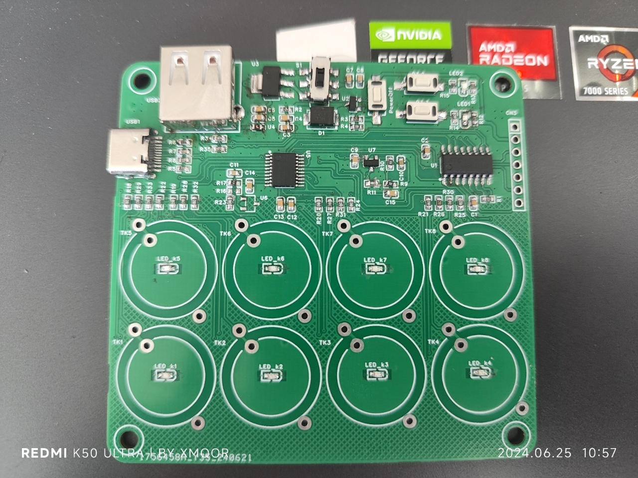
This is a copy of the original design, with optimized layout and circuitry. It has been verified. It comes in a standard version and an extended Type-C version; the only difference is that the extended Type-C version has longer Type-C pads for easier soldering. I recommend using the extended Type-C version for prototyping. The test code is poorly written; I suggest replacing the U2 and SS8550 with MOSFETs like AO3401 during soldering.
VID_20240625_102100.mp4
test_stc8h2k08t.zip
PDF_STC Touch Button Demo Board EDA Version.zip
Altium_STC Touch Button Demo Board EDA Version.zip
PADS_STC Touch Button Demo Board EDA Version.zip
BOM_STC Touch Button Demo Board EDA Version.xlsx
94053
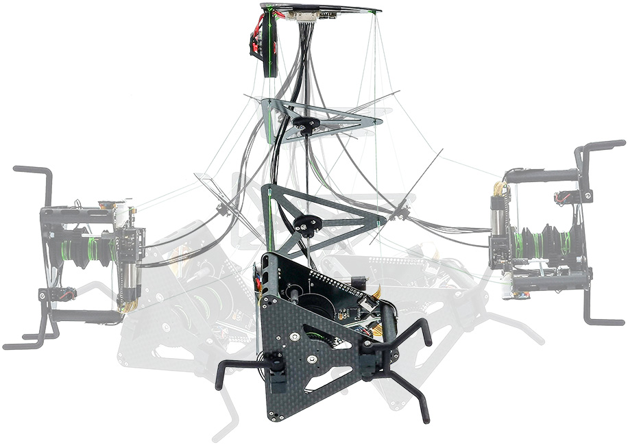
RGBlimp-Q control board for robot glider
PCB.RGBlimp-Q: Robotic Gliding Blimp With Moving Mass Control Based on a Bird-Inspired Continuum Arm
RGBlimp-Q: Robotic Gliding Blimp With Moving Mass Control Based on a Bird-Inspired Continuum Arm
This is the control unit circuit board for RGBlimp-Q.
Project Page
Paper
Video

Abstract
Robotic blimps, as lighter-than-air aerial systems, offer prolonged duration and enhanced safety in human-robot interactions due to their buoyant lift. However, robust flight against environmental airflow disturbances remains a significant challenge, limiting the broader application of these robots.
Drawing inspiration from the flight mechanics of birds and their ability to perch against natural wind, this article introduces RGBlimp-Q, a robotic gliding blimp equipped with a birdinspired continuum arm. This arm allows for flexible attitude adjustments through moving mass control to enhance disturbance resilience, while also enabling object capture by using claws to counteract environmental disturbances, similar to a bird. environments. To the best of the authors' knowledge, this is the first interdisciplinary design integrating continuum mechanisms onto robotic blimps. Experimental results from both indoor and outdoor settings validate the improved flight robustness against environmental disturbances offered by this novel design.
We have open-sourced the RGBlimp-Q hardware and code on GitHub.
PDF_Robot Glimp-Q Control Board RGBlimp-Q.zip
Altium_Robot Glimp-Q Control Board.zip
PADS_Robot Glimp-Q Control Board RGBlimp-Q.zip
BOM_Robot Glimp-Q Control Board RGBlimp-Q
94054
TPS5430 outputs 12V
This is a power module that I personally find quite useful. It has a 36V input withstand voltage and outputs including 12V, 5V, and 3.3V. It also includes a reserved port for main control power supply. Feedback and discussion are welcome.
The main chips used are TPS5430 and AMS1117 (both versions 3.3 and 5) to implement a multi-purpose power supply module. Test holes are reserved in the lower part of the board. Soldering can be done as shown in the example diagram, with the terminals soldered to the back for improved aesthetics.
VID_20240625_204640.mp4
PDF_TPS5430 Output 12V.zip
Altium_TPS5430 output 12V.zip
PADS_TPS5430 output 12V.zip
BOM_TPS5430 Output 12V.xlsx
94056
OpenMV4 - Four-layer board design
It has been verified to be usable and is an open-source OpenMV4 implementation I created for practice.
This open-source project is based on the open-source four-layer OpenMV (OpenMV4-H7-four-layer-JALCIC EDA open-source hardware platform (oshwhub.com)) by author M., with a redesigned layout and routing. It uses Type-C and places all components on the surface layer (which can be soldered directly on a hot plate).
This is for personal DIY only; please do not use it for profit.
The BOM is missing the main control chip, LEDs 1-6, the 24P-FPC socket, and several header pins. The chip can be either STM32H743VIT6 or STM32H750VBT6; the latter is much cheaper but has significantly less storage space. Both are usable. If the program is too large, it can be stored on an SD card. Purchase according to your needs. LEDs 5 and 6 are 1206-packaged 850nm infrared LEDs; the 24P FPC socket uses a flip-top, bottom-mounted 24P 0.5mm pitch design. (The camera stand is included with the purchase of the camera, but it's best to buy a few extra as spares.)
This project uses an FPC 0.5mm pitch 24P ribbon cable camera, which supports 30W pixel OV7725 and 200W pixel OV2640 (I haven't tried the 50W pixel OV5640, so I don't know if it will work). The higher the pixel count, the lower the frame rate. I personally recommend the OV7725, which can run at 40+ frames per second. (Search FPC OV7725 on Taobao)
Without further ado, here is a tutorial on burning firmware. There are many ways to burn firmware. Here is one of them:
1. Install and prepare the STM32CubeProgrammer software;
2. Use a TYPE-C cable and short-circuit RST and BOTO before powering on;
3. (1) Select the device connection interface (2) Select the USB connection mode (3) Search for the device (4) Click Connect Device;
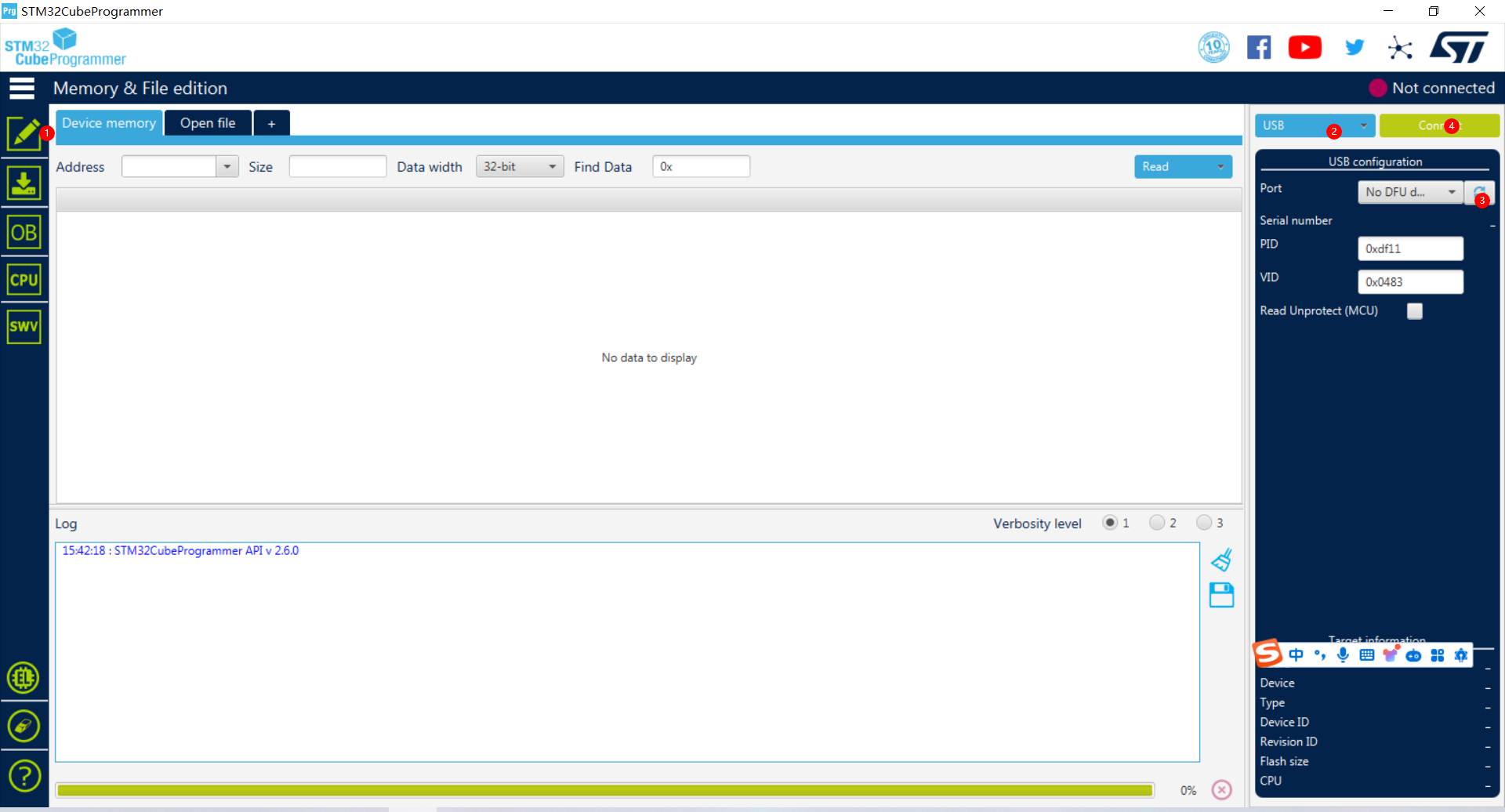
4. (1) Select the firmware download interface (2) Select the directory path of the firmware to be downloaded (e.g., if openmvIDE is installed, you can find it in its installation directory D: openmvIDEshareqtcreatorfirmwareOPENMV4) (3) Click Download and wait for the download to complete;

5. After downloading the firmware, power off and then power on again. OpenMV will automatically perform a self-test. After the self-test passes, a virtual USB drive will be generated on your computer. At this time, you can test and run the program using OpenMVIED.
Finally, here is the flashing software:
Link: https://pan.baidu.com/s/1C7j0j1l1R0fGCGecv4Kvfw Extraction code: jn7x
///--------Update------------
2024-5-7: I found that the SD card could not be recognized after insertion. Now I have replaced it with another SD card slot, and the PCB has been tested and verified that the SD card can be recognized.
openmv.bin
PDF_openmv4-Four-Layer Board Design.zip
Altium_openmv4-Four-Layer Board Design.zip
PADS_openmv4-Four-Layer Board Design.zip
BOM_openmv4-Four-Layer Board Design.xlsx
94057
electronic


 京公网安备 11010802033920号

 V80212SS05QE


