Project Development Progress
: June 10, 2024: Hardware circuit soldering completed; LED indicator lights and button detection functions debugged.
June 11, 2024: Optocouplers debugged; all optocouplers functioned correctly; OLED screen display information debugged. June 12, 2024
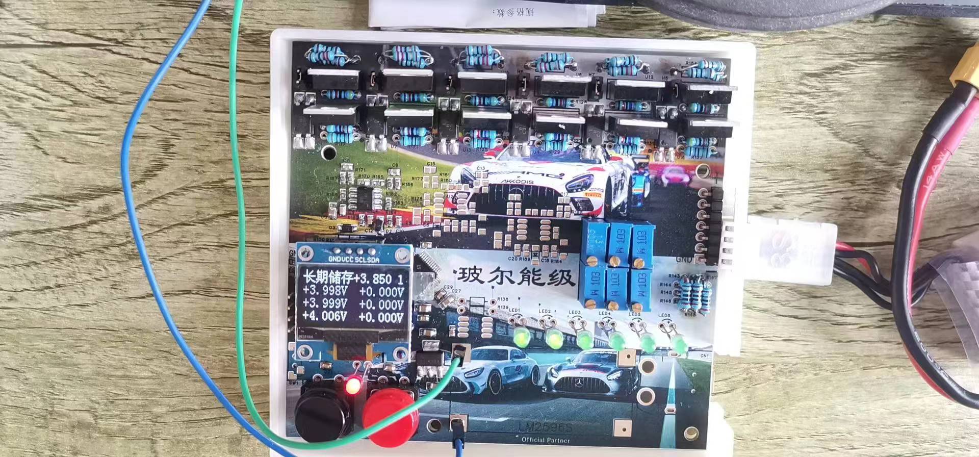
: Discharge function debugged; each discharge module continuously discharges the corresponding battery cell.
June 16, 2024: Battery long-term storage mode debugged; ADC voltage inaccuracy issue resolved.
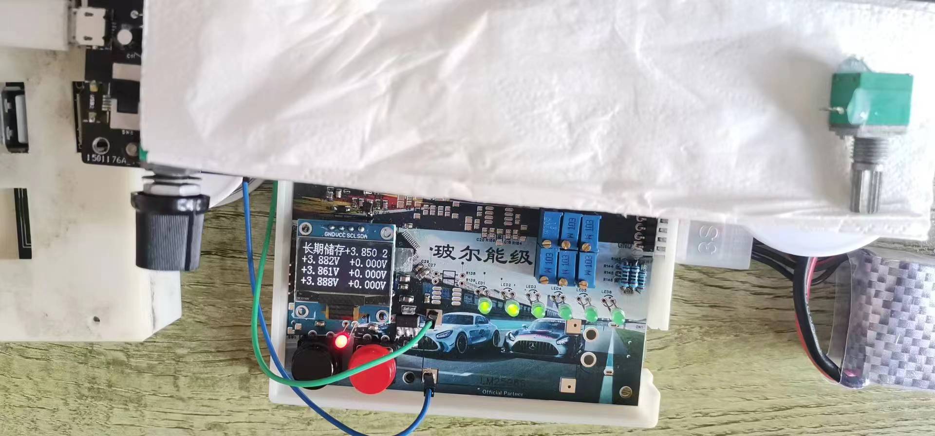
June 18, 2024: Battery cell balancing mode debugged; buzzer debugged; final program modification completed.
Introduction:
In today's society, mobile electronic devices are widely used, and lithium batteries, with their many advantages, play an indispensable role as the power source for these devices. The safety of lithium battery use and storage is equally important. If a fully charged battery is not used immediately for some reason and is left unused, it will gradually bulge over time. When the bulging reaches a certain extent, it may pose a risk of explosion, which is something we do not want to see. Therefore, a discharger with intelligent long-term storage mode and cell balancing mode was developed.
This
discharger can discharge lithium batteries that are not currently in use to a voltage suitable for battery storage, allowing the battery to maintain good performance even if it is not used for a period of time in the future. Simultaneously, it can balance battery cells, solving the problem of inconsistent voltage between different cells by making the voltage difference between cells similar.
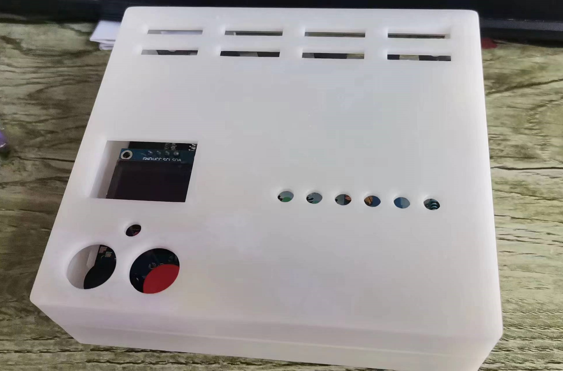
This discharger can perform the following functions:
It returns to the main interface after detecting no battery connection;
it can measure battery voltage and display the voltage of each cell;
if the battery is abnormally removed during discharge, it immediately shuts off the optocoupler, stops discharging, and returns to the main interface;
it stops discharging after reaching the preset discharge cutoff voltage and issues an alarm;
the current discharge mode can be exited at any time during discharge by pressing a button;
it has discharge speed (i.e., output current) adjustment, with the value displayed in the upper right corner of the OLED; the larger the value, the larger the output current.
Hardware Design
Project Hardware System Overview The N32G430 series
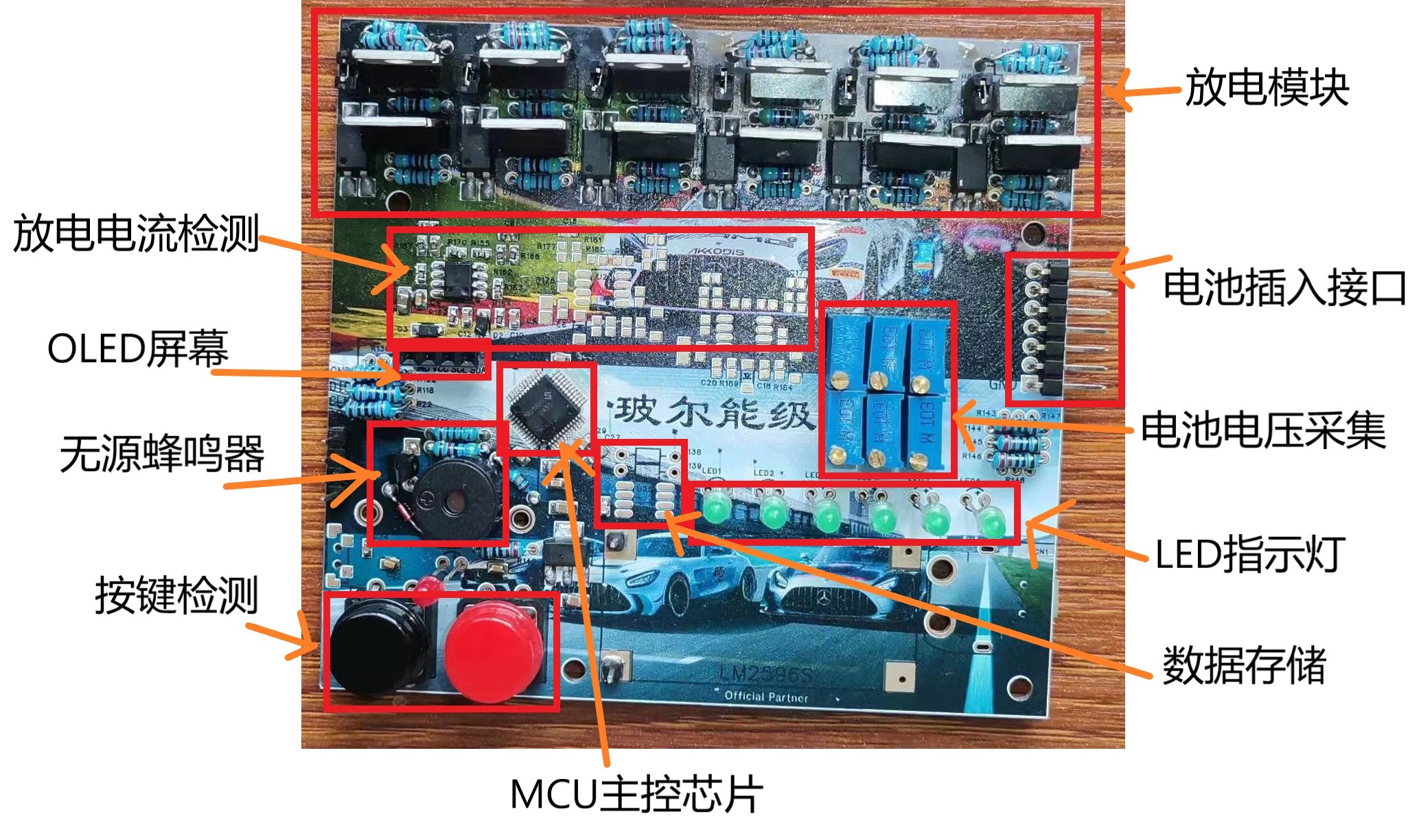
MCU main control chip
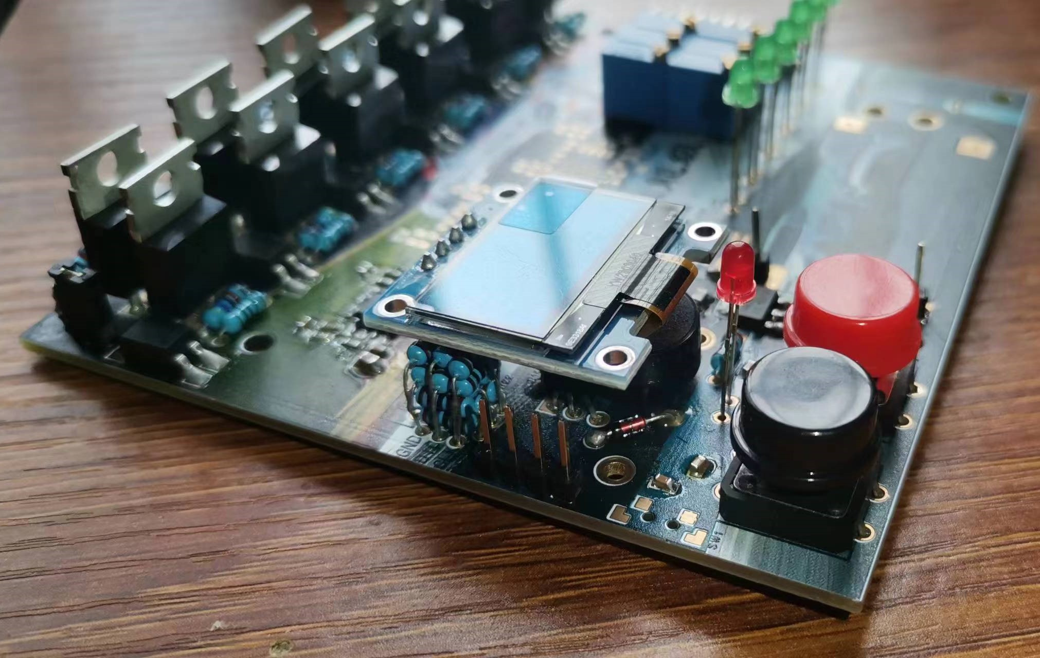
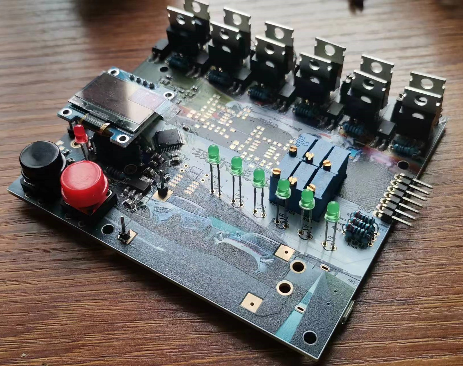
uses a 32-bit ARM Cortex-M4F core with a maximum operating frequency of 128MHz, supports floating-point operations and DSP instructions, integrates up to 64KB of embedded encrypted Flash, 16KB of SRAM, integrates rich high-performance analog devices, has a built-in 12-bit 4.7Msps ADC, 3 high-speed comparators, and integrates multiple U(S)ART, I2C, SPI, CAN and other digital communication interfaces. Based on the required functions and cost considerations of this project, the National Technology N32G430C8L7 MCU is used as the main control chip. Taking a specific discharge module as an example, the design concept of this circuit is analyzed:
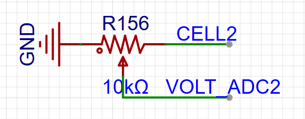
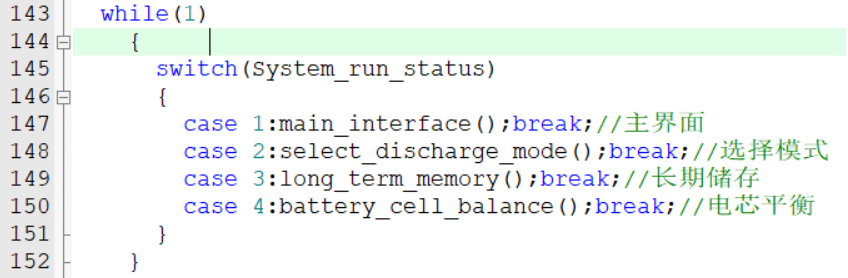
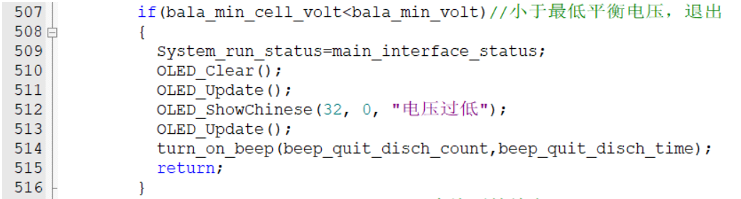
Optical couplers are used to achieve information transmission from input to output, which has two advantages: the output does not affect the input; and it solves the problem that the output terminal does not need to share a common ground with the input terminal. The Darlington circuit composed of PNP and NPN transistors can greatly increase the output current, with a current discharge multiple of β1 * β2. Pull-up resistors are added to the PNP transistors, and pull-down resistors are added to the NPN transistors to prevent interference to the base from causing the transistors to conduct when there is no operation. H4 is a pin header that can be connected to a multimeter to measure the output current; when not measuring, it can be shorted with a shorting cap. The information display uses a 0.96-inch 128*64 OLED to display necessary information for system operation. Battery voltage detection is typically achieved through resistor voltage division combined with the ADC of the main control chip, followed by proportional conversion to obtain the actual voltage. In this project, a potentiometer is used instead of a voltage divider resistor to acquire the battery voltage because the potentiometer can adjust the resistance value to obtain different voltage division ratios, which is more convenient than using a voltage divider resistor. Here's a method to quickly adjust the voltage divider ratio: As shown in the diagram above, given the MCU power supply voltage is 3.3V, the total value sampled by the 12-bit ADC is 4096, and the full-charge voltage of two cells connected in series is 8.4V. The first formula yields a voltage divider ratio of approximately 0.3928. Assuming the current total battery voltage is 8.0V, substituting this into the calculation, the second formula yields an ADC sampling voltage of approximately 3.14V. Finally, substituting this into the calculation , the actual ADC value is approximately 3897. Adjusting the potentiometer until the ADC value displayed on the OLED is around 3897 is sufficient. Two buttons are provided for convenient interaction with the discharger, used for entering the menu, switching discharge modes, exiting, etc. For sound prompts , considering the need for different frequencies of sound from the buzzer to indicate the current system state, a passive buzzer is chosen as the sound source. This allows for different tones to indicate different information such as entering a new mode, completing discharge, and abnormal battery removal. The discharge status LED indicator requires certain methods to determine whether the battery is currently discharging. This project uses LED indicators to represent the battery discharge status, with multiple LEDs representing the discharge status of each corresponding battery cell. A lit LED indicates that the corresponding cell is discharging, while a dark LED indicates that it is not discharging. Data storage uses the AT24C02 data storage chip. However, since there is currently no other data to store during normal operation of the discharger, this function is not used. Current detection uses a differential amplifier circuit composed of an LM358 integrated operational amplifier and peripheral circuitry to detect the discharge current. However, due to circuit design or interference, the current detected by the LM358 may differ significantly from the current detected by the multimeter; therefore, current detection is abandoned. The software design's main program runs in a while loop within the main function (as shown in Figure 1), continuously executing the switch function and checking the value of System_run_status to execute the corresponding entry function. The constants representing the states of these functions are defined in n32g430_it.c (as shown in Figure 2). If different functions need to be executed during system operation, the value of System_run_status can be modified via a button interrupt, assigning one of the four constants to System_run_status. Low voltage detection is shown in the figure above. If the current system is in cell balancing mode, it first checks if the detected cell voltage is lower than the rated voltage of 3.7V (because continuing to use it below this voltage will damage the battery). If it is lower than 3.7V, the value of System_run_status is modified, a low voltage warning is displayed, and the system returns to the main interface. Similarly, if the current system is in long-term storage mode, it first checks if the detected cell voltage is lower than the optimal long-term storage battery voltage of 3.85V. If it is lower than 3.85V, the value of System_run_status is modified, a low voltage warning is displayed, and the system returns to the main interface. Discharge rate adjustment.


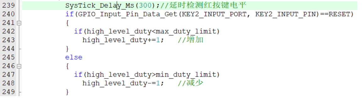
The discharge speed is adjusted using a single button, with options to increase and decrease the speed. To differentiate between these two, a long press increases the speed, and a short press decreases it. Specifically, after an interrupt is generated when the button is pressed, there's a delay of approximately 300 milliseconds, then the GPIO pin level is read. If the level is low (indicating the button is still pressed), the value of `high_level_duty` is incremented; if it's high (indicating the button is released), the value is decremented.
Buzzer parameters are defined
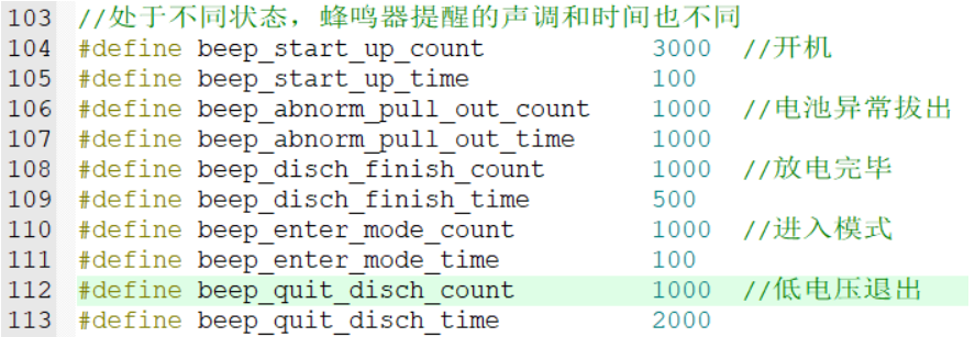
here, allowing users to adjust the tone and duration of the buzzer. This project, except for the OLED code which is ported from the author Jiangxie Technology, is entirely original in terms of algorithm and hardware design. You may use it in your personal development projects, but commercial use is strictly prohibited. The
attached 3D casing video demonstration includes videos showcasing long-term storage mode, cell balancing mode, and other functions. Due to the long discharge time, the videos have been sped up and edited.


 京公网安备 11010802033920号

 ABLSG-75.000MHZ-18-B-3-F-T


