
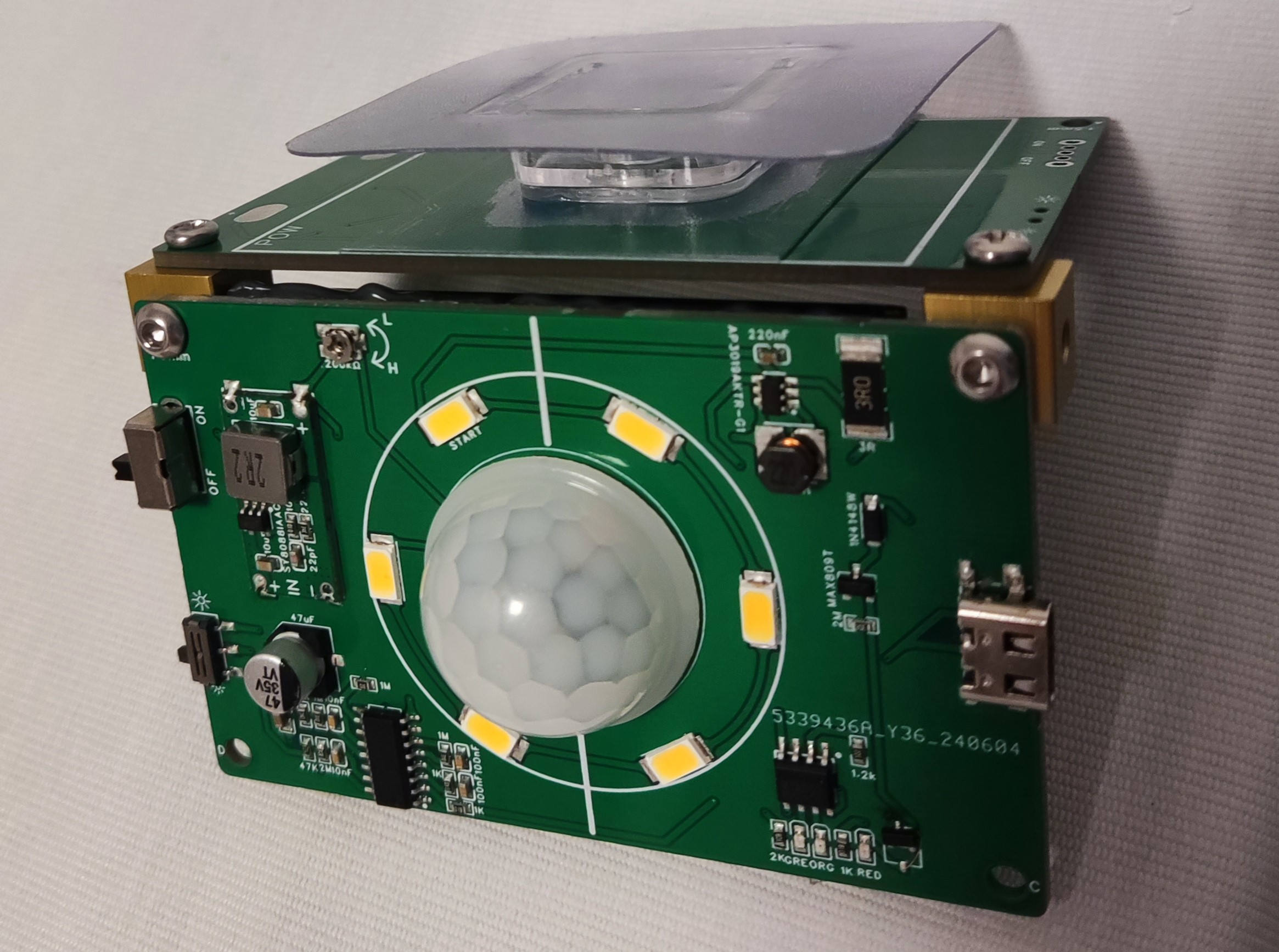
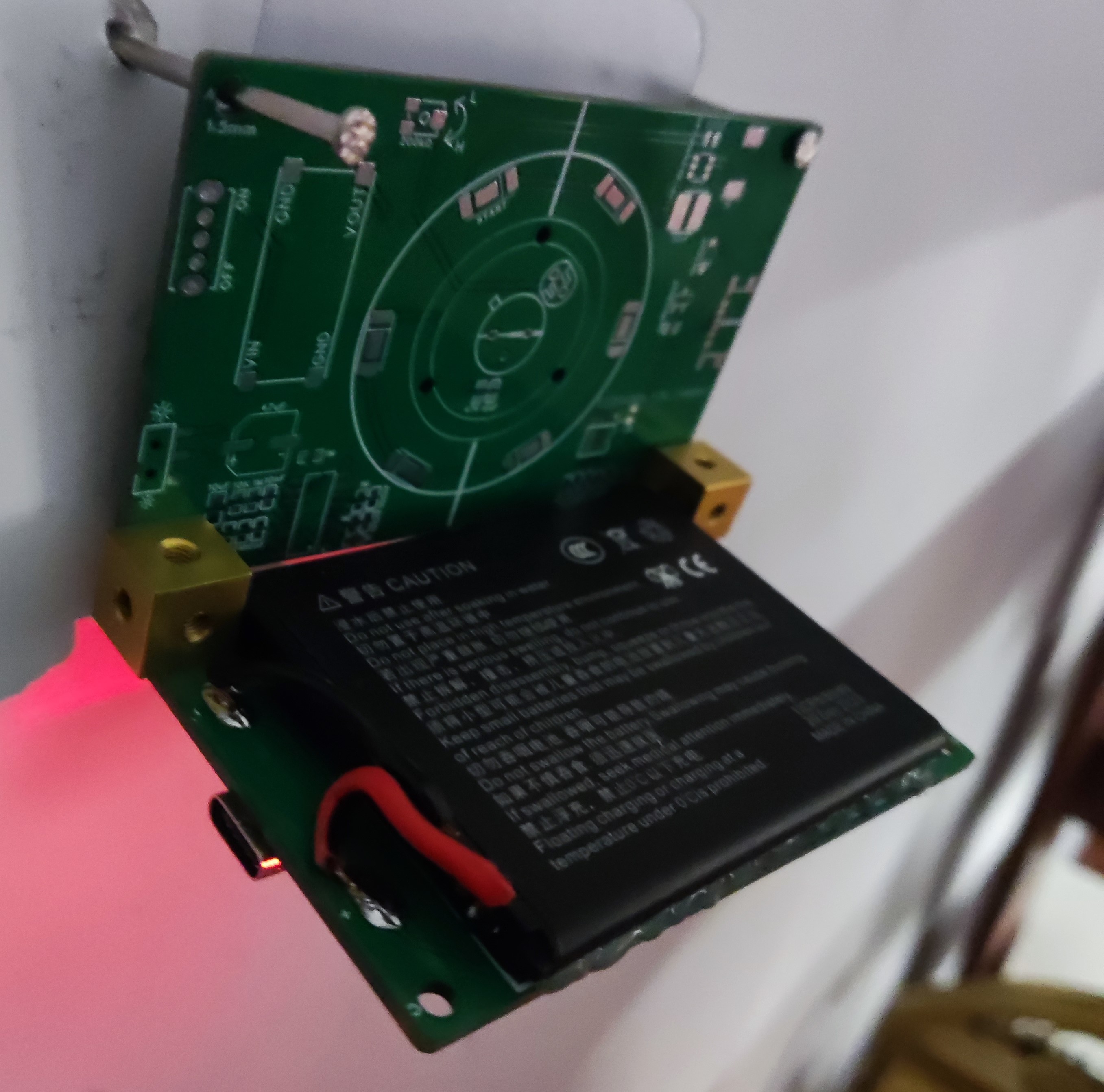
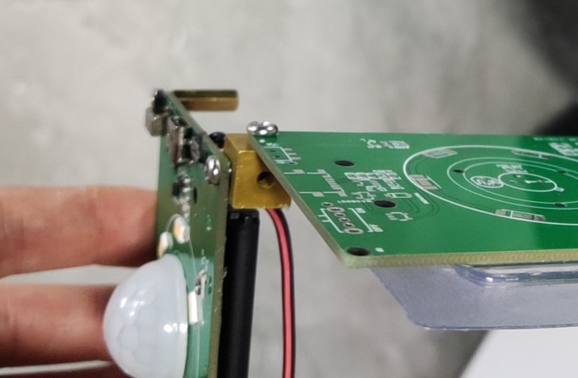
 illustration shows that a copper pillar can be used to elevate the back when 90-degree wall mounting is not required. Battery Precautions (Important): Use polymer batteries, with dimensions less than 63 * 50 mm. I cannot provide a purchase link; these were found elsewhere. Polymer batteries within this size range can be used. (Important) The power supply uses a SY8088AAC switching power supply chip, which is stacked on this board and cannot be purchased elsewhere!! (You can draw your own or use a voltage regulator chip). Do not directly connect a lithium battery to the main controller or infrared sensor. The unstable voltage of the lithium battery will definitely cause the infrared sensor to falsely trigger . The D204S is extremely easy to damage. Minimize soldering time. During soldering, it should be suspended 4mm away from the PCB; otherwise, it is easy to falsely trigger the low battery warning and the power will not disconnect when the main switch is turned off, causing a short circuit. The cost is around 10 RMB, plus the battery (I considered the battery as a find). The sensor and chip are relatively expensive . The LED color temperature can be adjusted. My mother likes white, but I prefer 4000k warm light. The hole size on the board is 1.5mm, and the radius is M3. Note this when purchasing (not important). The 4054 series can also be used for charging. I used it on a previous board; it charged at 3000mA overnight and the sky was already bright... (Not important) The large switch is the main power switch, and the small switch is for selecting the single-time light-on strategy; the headlight icon will remain constantly lit if triggered within n seconds (15 seconds in this solution); the small light icon will definitely turn off after n seconds, and the infrared probe signal will be read again after 1~2 seconds of signal stop. Materials not mentioned in the guide are available on Taobao and WeChat. Brand new PIR pyroelectric human infrared sensors D203S D203B D204S D204B D205B original ¥1.71; LED driver AP3019AKTR-G1; DIODES (US/Taiwan) SOT-23-6 silkscreen GAS brand new free shipping ¥0.5; Human body sensor BISS0001 UMW (Taiwanese semiconductor) SOP-16 universal infrared pyroelectric ¥0.5; M3M4/5/6/8 aluminum alloy six-sided three-way nut screw hole colored connecting block chassis shock-absorbing feet; DIY salvaged battery (reference link). 6. Strong waterproof bathroom adhesive multi-functional traceless snap-on clip for fixing power strips without drilling ¥4.5 TODO LIST Using nuts and nuts is just to avoid drawing the outer casing; I'll draw it when I have time... placeholder


All reference designs on this site are sourced from major semiconductor manufacturers or collected online for learning and research. The copyright belongs to the semiconductor manufacturer or the original author. If you believe that the reference design of this site infringes upon your relevant rights and interests, please send us a rights notice. As a neutral platform service provider, we will take measures to delete the relevant content in accordance with relevant laws after receiving the relevant notice from the rights holder. Please send relevant notifications to email: bbs_service@eeworld.com.cn.
It is your responsibility to test the circuit yourself and determine its suitability for you. EEWorld will not be liable for direct, indirect, special, incidental, consequential or punitive damages arising from any cause or anything connected to any reference design used.
Supported by EEWorld Datasheet
EEWorld
subscription
account

EEWorld
service
account

Automotive
development
community

Robot
development
community

About Us Customer Service Contact Information Datasheet Sitemap LatestNews


Room 1530, 15th Floor, Building B,
No.18 Zhongguancun Street,
Haidian District,
Beijing, Postal Code: 100190
China
Telephone: 008610 8235 0740
 京公网安备 11010802033920号

 FCC17-A15AD-2OOG


