Currently, I've only completed the physical prototype following the Taishanpai training camp instructions, without adding my own ideas. Firstly, my skill level is limited; secondly, I've been too busy lately to focus on completing subsequent expansions (I'll do that when I have time). The Taishanpai mini-phone open-source website is: https://oshwhub.com/li-chuang-kai-fa-ban/tai-shan-pai-pang-niu-shou-ji-kuo-zhan-ban.
All resources can be found at this website provided by the LCSC team. We look forward to your DIY projects!
Related tutorial videos can also be viewed on Billboard: Open Billboard -> Search for LCSC development boards -> Find the Taishanpai column.
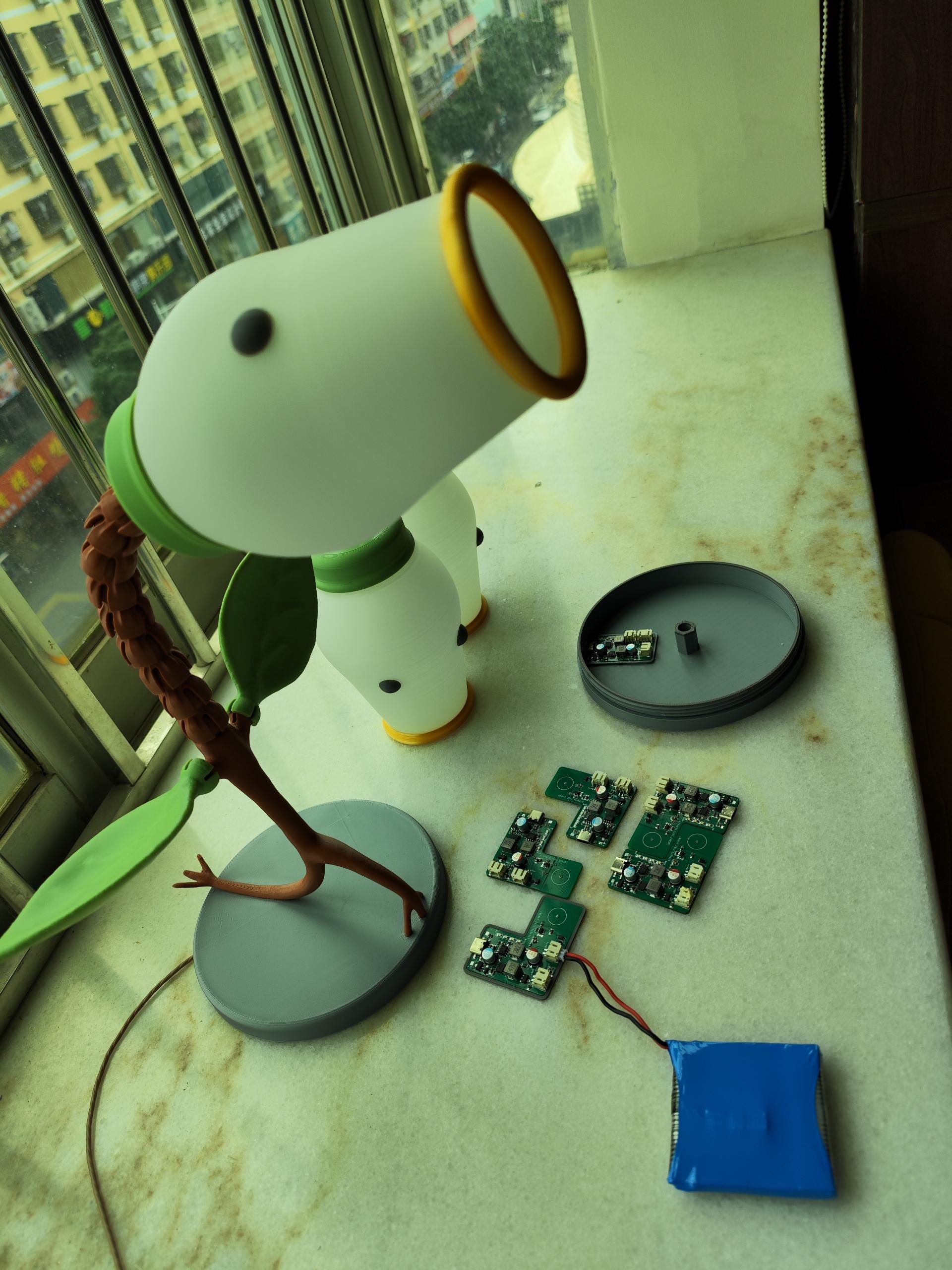
The finished product is shown in the image.

PDF_A Small Mobile Phone Based on the Taishan School.zip
Altium - A small mobile phone based on the Taishan School.zip
PADS_A small mobile phone based on the Taishan School.zip
BOM_Based on Taishanpa's Small Mobile Phone.xlsx
94779
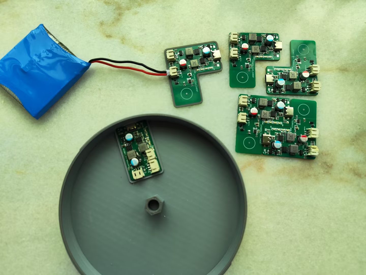
RadarLight
Touch-sensitive stepless dimming control board designed for the open-source model "Pea Shooter Lamp"
Pea Shooter Lamp Model: Key
Design Highlights:
1. Standby power consumption 200uA
; 2. Touch switch, stepless dimming
; 3. Supports same-port charging and discharging of lithium batteries;
4. High-efficiency LED constant current drive circuit.
(Bilibili video: https://b23.tv/tw2pD4v)
PDF_RadarLight.zip
Altium_RadarLight.zip
PADS_RadarLight.zip
BOM_RadarLight.xlsx
94780
Smart Home Gateway
Smart home project, Raspberry Pi expansion board gateway
This project is the gateway part of a smart home project.
The entire project is divided into three parts:
1. Zigbee switch_power board
(1) Input AC 220V
(2) 3-way relay output
2. Zigbee switch_control board
(1) Zigbee module, receives gateway commands
(2) Touch button, manually control relays (ceiling light)
3. Gateway
(1) This module is an expansion board of Raspberry Pi
(2) Zigbee module, receives the status of the switch and transmits it to the server through the WiFi of Raspberry Pi.
Receive commands from the server and send them to the designated switch
PDF_SmartHome_Gateway.zip
Altium Smart Home Gateway.zip
PADS_SmartHome_Gateway.zip
BOM_SmartHome_Gateway.xlsx
94781
Smart Home Zigbee Switch Control Board
The control panel in the Zigbee wall switch for a smart home project.
This project is the control board part of the smart home project.
The entire project is divided into three parts:
1. Zigbee switch_power board
(1) Input AC 220V
(2) 3-way relay output
2. Zigbee switch_control board
(1) Zigbee module, receives gateway commands
(2) Touch button, manually control relays (ceiling light)
3. Gateway
(1) This module is an expansion board of Raspberry Pi
(2) Zigbee module, receives the status of the switch and transmits it to the server through the WiFi of Raspberry Pi.
Receive commands from the server and send them to the designated switch
PDF_Smart Home_Zigbee Switch Control Board.zip
Altium Smart Home Zigbee Switch Control Board.zip
PADS Smart Home Zigbee Switch Control Board.zip
BOM_Smart Home_Zigbee Switch Control Board.xlsx
94782
Smart Home_Zigbee Switching Power Supply Board
Smart home project, power board in Zigbee wall switch
This project is the power board part of a smart home project.
The entire project is divided into three parts:
1. Zigbee switch_power board
(1) Input AC 220V
(2) 3-way relay output
2. Zigbee switch_control board
(1) Zigbee module, receives gateway commands
(2) Touch button, manually control relays (ceiling light)
3. Gateway
(1) This module is an expansion board of Raspberry Pi
(2) Zigbee module, receives the status of the switch and transmits it to the server through the WiFi of Raspberry Pi.
Receive commands from the server and send them to the designated switch
PDF_Smart Home_Zigbee Switching Power Supply Board.zip
Altium Smart Home Zigbee Switching Power Supply Board.zip
PADS Smart Home Zigbee Switching Power Supply Board.zip
BOM_Smart Home_Zigbee Switching Power Supply Board.xlsx
94783
OPEN HMI
OPEN HMI is an open-source, low-cost industrial control panel project.
The OPEN HMI includes the following functions:
1. 2-channel relay output --- Test completed
2. 5-inch LCD screen --- Test completed
3. 4-channel isolated input --- Test incomplete
5. SPI FLASH --- Test completed
Debugging Notes:
I. Hardware Modification Instructions
1. SDIO interface requires pull-up, wiring needs adjustment
II. SPI flash program burning
command: sudo sunxi-fel -p spiflash-write 0 flashimg.bin
Note: After entering FEL mode, the CS and GND of the SPI flash must be disconnected before executing the above command.
III. Screen Calibration
In the development board command terminal, enter:
vi /etc/profile
Insert the following code at the last line:
NormalText Code
123456
export TSLIB_TSDEVICE=/dev/input/event0 export TSLIB_CALIBFILE=/etc/pointercal export TSLIB_CONFFILE=/etc/ts.conf export TSLIB_PLUGINDIR=/usr/lib/ts export TSLIB_CONSOLEDEVICE=none export TSLIB_FBDEVICE=/dev/fb0
IV. Change the LCD screen RGB666 to BGR666.
This change is for easier hardware wiring.
Linux/drivers/gpu/drm/sun4i/sun4i_tcon.c
123456789101112131415161718192
static void sun4i_tcon_channel_set_status(struct sun4i_tcon *tcon, int channel, bool enabled){ struct clk *clk; switch (channel) { case 0: regmap_update_bits(tcon->regs, SUN4I_TCON0_CTL_REG, SUN4I_TCON0_CTL_TCON_ENABLE, enabled ? SUN4I_TCON0_CTL_TCON_ENABLE : 0); regmap_update_bits(tcon->regs, SUN4I_TCON0_CTL_REG,BIT(23),BIT(23));//SWAP R, B pin clk = tcon->dclk; break; case 1: WARN_ON(!tcon->quirks->has_channel_1); regmap_update_bits(tcon->regs, SUN4I_TCON1_CTL_REG, SUN4I_TCON1_CTL_TCON_ENABLE, enabled ? SUN4I_TCON1_CTL_TCON_ENABLE : 0); clk = tcon->sclk1; break; default: DRM_WARN("Unknown channel... doing nothing
"); return; } if (enabled) clk_prepare_enable(clk); else clk_disable_unprepare(clk);}
Reference project:
lichee Nano The development board
will be continuously updated.
GPIO_TEST.zip
LVGL_TEST.zip
PDF_OPEN HMI.zip
Altium_OPEN HMI.zip
PADS_OPEN HMI.zip
BOM_OPEN HMI.xlsx
94784
433M Wireless Controller - Slave
The 433M wireless controller uses the 433M frequency and a one-to-many communication method, that is, one master controls multiple slaves, so as to control and manage the equipment in a factory.
I. Wireless Controller Communication Method
The 433M wireless controller (hereinafter referred to as the wireless switch) adopts a one-to-many communication method, that is, one master communicates with multiple slaves through polling. This control system supports a maximum of 20 slaves. The PC-side host computer software can configure and acquire the status of the slaves.

II. Wiring Method

Wiring Pin Description
Terminal
Function
Master
Slave
+12V
Controller Power Supply Interface
Connect
to
GND
RA
Load Circuit Interface
Not Connected
Connect to
RA
RB
Load Circuit Interface
Not Connected Connect to RB RC Load Circuit Interface Not Connected Connect to RC RD Load Circuit Interface Not Connected Connect to RD B RS485 Communication Interface Connect to A NC Empty Interface Not Connected Not Connected 3V3 Photoresistor Interface Not Connected Connect to GND LIN COM Load Current Detection Not Connected Connected to CT Note: The controller electrical interface and the photoresistor interface are directional and cannot be reversed.
PDF_433M Wireless Controller-Slave Unit.zip
Altium_433M Wireless Controller - Slave Unit.zip
PADS_433M Wireless Controller - Slave Unit.zip
BOM_433M Wireless Controller-Slave Unit.xlsx
94785
433M Wireless Controller - Main Unit
The 433M wireless controller uses the 433M frequency and a one-to-many communication method, that is, one master controls multiple slaves, so as to control and manage the equipment in a factory.
I. Overview
1.1 Wireless Controller Communication Method
The 433M wireless controller (hereinafter referred to as the wireless switch) adopts a one-to-many communication method, that is, one master communicates with multiple slaves through polling. This control system supports a maximum of 20 slaves. The host computer software on the PC can configure and acquire the status of the slaves.
The PC sends commands to the master via RS485, and the master then sends the commands to the corresponding slaves via the 433M wireless communication module. Upon receiving the command, the slave sends its status to the master via the 433M module, and the master then sends the slave status to the host computer via RS485.
1.2 Performance Parameters
1.2.1 Master Interface
Interface Name
Quantity
Function
RS485
1 Communication
with PC
Relay
1
Alarm Output
LED
2
Power Indicator, Fault Indicator Status
Debugging Interface
1
Note: The fault indicator flashes once per second (slow flashing) to indicate normal communication; flashing once every 0.5 seconds (fast flashing) indicates that the slave cannot communicate. Occasionally, a fast flash is normal.
1.2.2 Slave Interface
Interface Name
Quantity
Function
Relay
4
Circuit control, load current 5A
LED
7
Power indicator, relay status indicator, fault indicator
CT Input
1
Detects load
Photoresistor Interface
1
Detects ambient light level
Debug Interface
1
Note: The fault indicator flashes once per second (slow flashing) to indicate normal communication; flashing once every 0.5 seconds (fast flashing) indicates that the slave device cannot communicate. Occasionally, a fast flash is normal.
II. Host Computer Software
2.1 Interface Introduction
Main Interface
When you open the host computer, the first screen that appears is the boot screen, and then you enter the main interface. As shown in the figure below, the main interface is described as follows:
Label
Name
Remarks
1
Toolbar
is mainly used for serial port disconnection and connection, configuration interface opening, and relay full on/off operations.
2
Address Code Indicator
Indicates address information.
3
Function Indicator
4
Status Information Indicator
Relay status indication, load information, and alarm information.
5
Communication Status Indicator
Indicates serial port communication status information.
Configuration Interface
Click the configuration button in the toolbar to enter the configuration interface. The configuration interface is shown in the figure below:
Label
Name
Remarks
1.
Serial Port Selection
Select the serial port number to connect to the host .
2.
Mode Setting
Select the mode
. 3.
Scheduled Time
Setting Waiting time for the relay to open after each power outage and power-on.
4.
Time Preset
In time preset mode, set the time to open and close the relay.
5.
Switch Setting Configure
the relay name and enable settings for the slave device
. 2.2 Using the Host Computer Software
2.2.1 Connecting to the Serial Port Instructions
Operation Steps: 1. Enter the configuration interface and select the serial port
. 2. Close the configuration interface and enter the main interface. Click the "Connect to Serial Port" button in the toolbar.
3. Observe the prompt information in the status bar.
Prompt Information
Description
Connected to COM10:19200,8,N,1
This indicates that the serial port is connected, but the host computer and the host cannot communicate.
Opening Failure
Indicates that the current serial port is occupied.
PC and master time synchronization failure!
Indicates that the communication between the host computer and the host is unstable
. PC successfully obtains the slave status.
Indicates that the serial port connection is normal .
2.2.2 Closing the Serial Port
Operation Steps:
1. Enter the main interface and click the "Close Serial Port" button in the toolbar.
2.2.3 Slave Configuration Instructions:
The following example illustrates how to configure slave devices: Three slave devices are set up with addresses 0, 1, and 3.
Address 0: RA (Room 101, valid) RB (Room 102, valid) RC (Room 103, invalid) RD (Room 104, invalid)
Address 1: RA (Room 201, invalid) RB (Room 202, invalid) RC (Room 203, valid) RD (Room 204, valid)
Address 3: RA (Room 401, invalid) RB (Room 402, valid) RC (Room 403, valid) RD (Room 404, invalid)
Operation Steps:
1. Repeat section 2.2.1 to ensure a normal serial port connection.
2. Enter the configuration interface and configure the relays.
3. Click the "Set" button to complete the settings.
4. Close and reopen the host computer software. The slave device configuration is successful.
5. If the following error occurs, ensure normal communication between the host computer and the master computer, and then try again.
2.2.4 Manual Mode Instructions:
The "All On/All Off" button in the toolbar is only available in manual mode; clicking it in other modes has no effect. Only in manual mode can the switching action of the circuit be changed by clicking the relay status lights on the main interface. To switch to manual mode, please follow these steps:
1.
Repeat section 2.2.1 to ensure a normal serial port connection.
2. Enter the configuration interface and select manual mode.
3. If the following error occurs, please ensure that the communication between the host computer and the main unit is normal, and then try again.
2.2.5 Photoresistor Mode Instructions
Before switching to photoresistor mode, you need to connect the photoresistor module to the slave device, paying attention to the wiring sequence. The sensitivity of the photoresistor module can also be adjusted by turning the potentiometer. To switch to photoresistor mode, please follow these steps: Operation Steps:
1. Repeat section 2.2.1 to ensure the serial port connection is normal.
2. Enter the configuration interface and select photoresistor mode
. 3. If the following error occurs, please ensure that the communication between the host computer and the main unit is normal, and then try again.
2.2.6 Time Preset Mode
The time preset mode is divided into two types: "Daily" and "Once". The "Daily" mode only requires information about the hour and minute, not the year, month, and day; the "Once" mode requires information about the year, month, day, hour, and minute. To switch to time preset mode, please follow these steps.
Operation Steps:
1. Repeat section 2.2.1 to ensure a normal serial port connection
. 2. Set the preset time.
2. Enter the configuration interface and select the preset time mode.
3. If the following error occurs, please ensure that the communication between the host computer and the main unit is normal, and then try again.
Example: Preset Time
Mode
Explanation
: The slave device will be on continuously after 15:00 on 2017-07-28.
The slave device will be off continuously after 20:30 on 2017-07-28
. The slave device will be on continuously between 18:00 on 2017-07-28 and 6:00 on 2017-07-29, and will be off continuously after 6:00 on 2017-07-29
. The slave device will be on at 20:00 every day and off at 5:00.
2.2.7 Time Reservation Setting:
The time reservation is the time the relay waits to close after the slave device is powered off and then powered on again. Please set it according to the following steps.
Operation steps:
1. Repeat section 2.2.1 to ensure the serial port connection is normal.
2. Switch to the configuration interface and set the appointment time.
PDF_433M Wireless Controller - Main Unit.zip
Altium_433M Wireless Controller - Main Unit.zip
PADS_433M Wireless Controller - Main Unit.zip
BOM_433M Wireless Controller - Main Unit.xlsx
94788
MODBUS Remote I/O Module
1. Industrial-grade control module
2. Standard MODBUS RTU
3. 8-channel dry contact input
4. 5-channel relay output

Features:
Multi-baud rate support
: Supports 9600, 19200, 38400, 57600, and 115200 baud rates.
Multi-station number support
: Supports broadcasting, with station numbers set from 1 to 255.
Dual watchdog timer
. Imported MCU
: Imported MCU main chip from a major international manufacturer, ensuring more stable performance. High
-quality relays
: Uses high-quality Hongfa relays for superior control.
Standard MODBUS
: Uses the standard MODBUS protocol, supporting Modbus Poll.
Intelligent host computer
: Intelligent host computer, easily handling function configuration and relay control.
Parameters
: Product Model:
WD_08D_05R_0A_0D.
Input signals:
8-channel dry contact input.
Operating power supply
: Wide voltage DC 7~36V,
maximum power consumption
2.5W.
Output method:
5-channel relay output, maximum load per channel 10A.
Communication interface
: RS485 standard Modbus RTU communication protocol .
Product dimensions:
95*90*40mm (L*W*H).
Installation dimension:
35mm standard DIN rail slot.
Controller address allocation
function :
Address
function
: Remarks :
Input address :
0x0000
IN0
0x0001
IN1
0x0002
IN2
0x0003
IN3
0x0004
IN4
0x0005
IN5
0x0006
IN6
0x0007
IN7
Output Address
0x1000
OUT0
0x1001
OUT1
0x1002
OUT2
0x1003
OUT3
0x1004
OUT4
Read/Write Register
0x2000
Device ID Number
Range (1~255), Default is 1
0x2001
Baud Rate Setting
0x1000 Baud Rate 2400 0x2000
Baud Rate 4800
0x3000 Baud Rate 9600
0x4000 Baud Rate 19200
0x5000 Baud Rate 38400
0x6000 Baud Rate 57600
0x7000 Baud Rate 115200
0x2002
Control Mode
: 0: Remote control;
1: Local control.
0x2003
Input Mode
: 0: Normal contact;
1: Short contact.
0x2004
Reserved
; 0x2005
Reserved
; 0x2006
Reserved
; 0x2007
Reserved ;
0x2008
Reserved
; 0x2009
Reserved
Read-Only Register
. 0x6000
Controller Model:
0x6001
0x6002
0x6003
0x6004
0x6005
0x6006
0x6007
0x6008
Controller Software Version .
Mode Description:
Input
Mode: There are two input modes: normal contact and short contact. In normal contact mode, the input is ON when closed and OFF when open. In short contact mode, the state reverses once when the input is closed.
Control Mode:
There are two control modes: remote and local. In remote mode, inputs and outputs are independent; the user can control the opening and closing of the output via commands
. In local mode, the controller's first 5 input points (IN0~IN4) and 5 output points (OUT0~OUT4) are interconnected; commands cannot control the outputs in this mode. In
remote mode ,
the status is read via commands
: IN0
IN1 IN2 IN3
IN4 IN5 IN6 IN7 . Commands control OUT0 OUT1 OUT2 OUT3 OUT4. In local mode , the status is read via commands: IN0 IN1 IN2 IN3 IN4 IN5 IN6 IN7 OUT0 OUT1 OUT2 OUT3 OUT4. (Applicable enclosure)


WD_08D_05R Protocol Manual V1.00.pdf
WD Configuration Tool V1.00.exe
Demo video.mp4
PDF_MODBUS Remote I/O Module.zip
Altium_MODBUS Remote I/O Module.zip
PADS_MODBUS Remote I/O Module.zip
BOM_MODBUS Remote I/O Module.xlsx
94789
electronic


 京公网安备 11010802033920号

 XR73-20


