1. Introduction
In this project, we use the CW32F030K8U7 to design a drill drive board, using an 18V battery pack. Recommended power is 100~200W. This drive board features undervoltage protection, overvoltage protection, overcurrent protection, stall protection, power detection, forward/reverse switching, and braking functions. It can be widely used in the control of various brushless motors.
2. Hardware Composition
The CW32 drill drive board hardware design consists of three parts: brushless drive circuit, power control circuit, and microcontroller and peripherals.
2.1 Brushless Motor Drive
The brushless motor drive is further divided into back EMF detection, current acquisition, power supply voltage acquisition, and MOS drive circuit. The MOS drive chip used is FD6288.
2.1.1 Back EMF Detection
According to Faraday's law of electromagnetic induction and Lenz's law, when the rotor rotates, an induced electromotive force (EMF) is generated in the stator windings. The direction of this induced EMF is opposite to the winding voltage, and its polarity is opposite to the excitation voltage; therefore, it is generally called back EMF.
2.1.2 Power Supply Voltage Acquisition
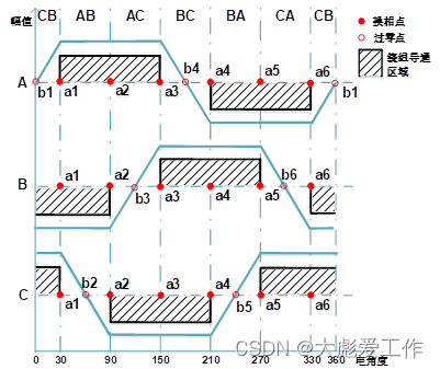
During the operation of the brushless motor, the bus voltage needs to be compared with the terminal voltage of the floating phase in each control cycle to obtain the zero-crossing point of the back EMF. After detecting the zero-crossing of the back EMF, a commutation operation can be performed after a 30° electrical angle delay. When acquiring the voltage during the PWM off-time, the theoretical neutral point voltage is 0V; when acquiring the voltage during the PWM on-time, the theoretical bus voltage is half of the power supply voltage.

Since half of the bus voltage needs to be compared with the back EMF to determine the zero point position when sampling at TON time, in the circuit design, we directly set the voltage divider resistors of the power supply voltage acquisition circuit to 200k and 5.1k, which is half of the voltage division ratio of the back EMF acquisition circuit mentioned above. This way, the value acquired by the ADC does not require extra calculations, reducing the burden on the MCU.
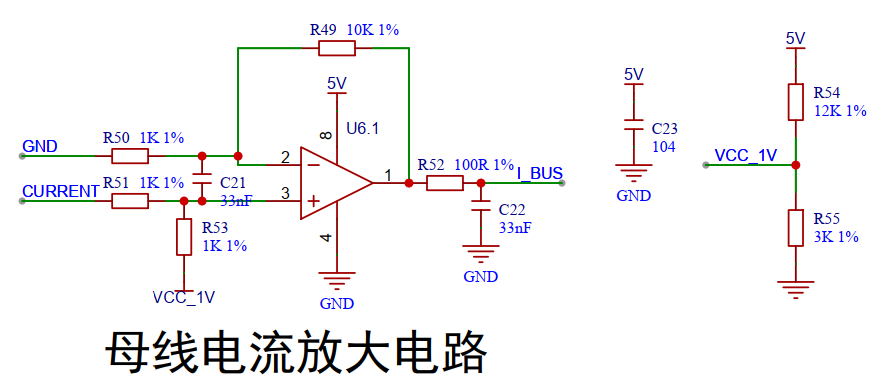
2.1.3 Current Voltage Acquisition
In this project, an operational amplifier is used to amplify the voltage across the sampling resistor, with a bias voltage of about 1V and an amplification factor of 11 times.
2.1.4 MOS Drive Circuit
The FD6288 is used as the drive chip for the gate MOS in this project. The FD6288T&Q is an integrated circuit chip that integrates three independent half-bridge gate drive chips. It is designed for high-voltage, high-speed drive MOSFETs and can operate at voltages up to +250V. The FD6288T&Q has built-in VCC/VBS undervoltage (UVLO) protection to prevent the power transistor from operating at too low a voltage. The FD6288T&Q has built-in shoot-through protection to prevent dead time and prevent the driven high and low side MOSFETs from shoot-through, effectively protecting the power devices. The FD6288T&Q has built-in input signal filtering to prevent input noise interference.

2.2 Power Control Circuit
2.2.1 Power-on Logic
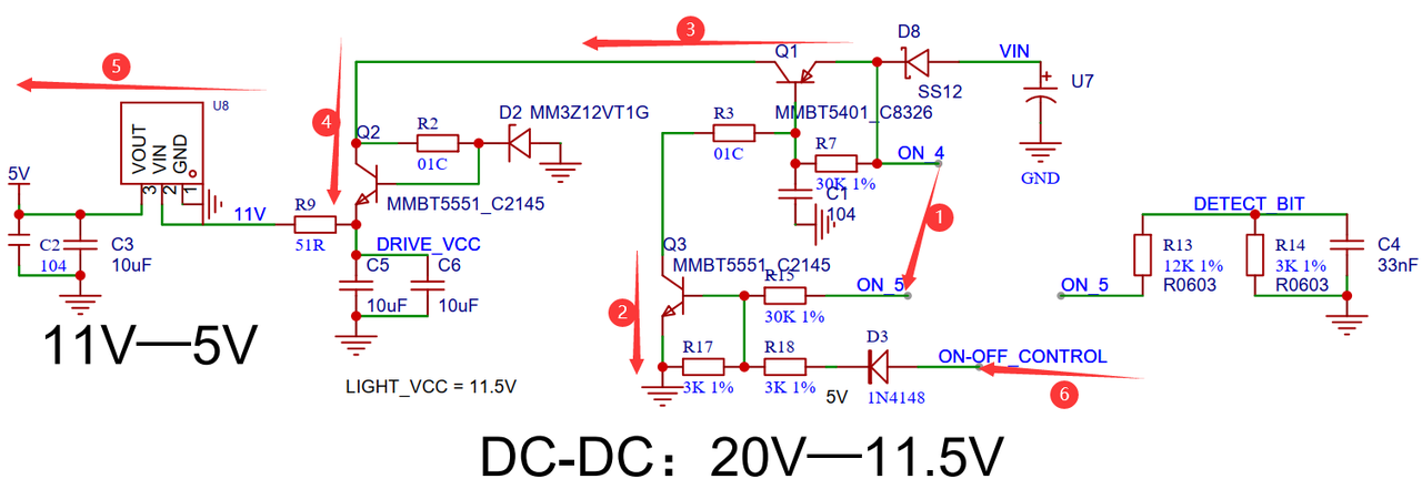
(1). When the slider on the electric drill is pressed, NO_4 and NO_5 in the figure above will be connected together. VIN will flow through the diode and current-limiting resistor through the base of the transistor and finally return to the negative terminal of the power supply.
(2). The base of transistor Q3 is forward biased and the transistor is turned on.
(3) The base of transistor Q1 is grounded, and the transistor is turned on.
(4) After passing through the Zener diode, the voltage of VIN drops to about 11.5V.
(5) After passing through an LDO, the 11.5V voltage is stabilized to 5V, which is used to power the microcontroller.
(6) When the microcontroller is powered on, it will pull the ON-OFF_CONTROL pin high, so that transistor Q3 is always turned on, and the entire power supply section completes self-locking.
2.3 Microcontroller and Peripherals
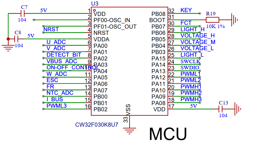
This project uses the CW32F030 series MCU, which adopts an advanced processor architecture and a high-frequency CPU, and has high computing power and response speed. It can handle complex algorithms and tasks, and has good performance in applications with high real-time requirements. In addition, CW32 can maintain low power consumption during operation through optimized power management technology and low power consumption design. CW32 is a widely used microcontroller with a large development community and resource support. Developers can easily access a wealth of official documentation, software development tools, and examples, as well as experience sharing and technical support from other developers.
2.3.1 Microcontroller Core System
3. Programming Instructions
Because the back electromotive force (EMF) of the stator windings of a brushless DC motor is proportional to the motor's speed, the back EMF is zero when the motor is stationary or very small at low speeds. In such cases, the rotor pole position cannot be determined based on the back EMF signal. Therefore, the back EMF method requires a special starting technique, accelerating from a standstill until the speed is sufficiently high. When the back EMF detects a zero crossing, the system switches to brushless DC motor operation. This process is called "three-stage" starting, mainly including rotor pre-positioning, acceleration, and operating state switching. This ensures both controllable motor direction and reliable starting by guaranteeing that the motor reaches a certain speed before switching.

For detailed program breakdown, please refer to the Feishu link:
https://dwi41yhz703.feishu.cn/docx/HY4Kd4bXToW2HOxD5wucp8zEnWf?from=from_copylink
. The open-source software documentation is included in the project attachments.
For demonstration videos and hardware/software explanations, please follow us on Bilibili (ID: CW32EcosystemCommunity).
For any questions, please follow the CW32EcosystemCommunity WeChat official account and contact us.
For chip selection or technical support in product development, please contact Mr. Li from the CW32EcosystemCommunity: 18769458853 (WeChat and mobile number are the same).


 京公网安备 11010802033920号

 MR821
MR821


