 However, there are noticeable differences in actual use.
 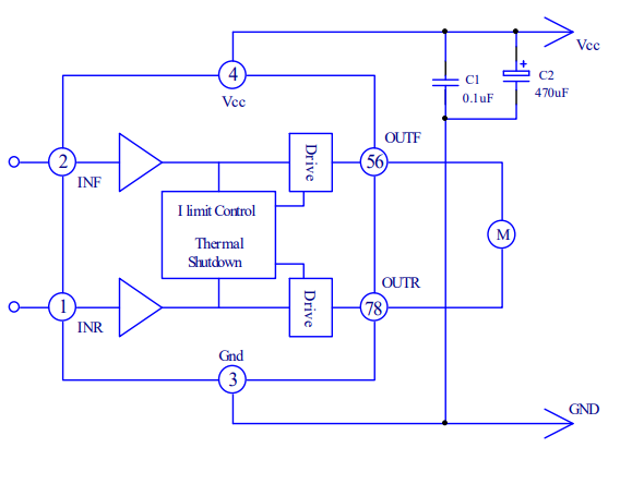 However, the BDR6126D application diagram recommends an external capacitor for VCC. I didn't include this in my simplified version.
  In hindsight, this is quite dangerous; decoupling capacitors are crucial. They need to be at least 100uF, a value that's difficult for a 0603 package, and the rated voltage needs to be at least 7.4V. Tantalum and aluminum electrolytic capacitors seem the most reliable options.
  Secondly, in my own testing, PWM has no control effect on the BDR6126D; the input PWM wave cannot achieve the effect of speed regulation of the motor (it works after retesting, updated 2024.4.24). The following is the input control timing diagram of the BDR6126D.
 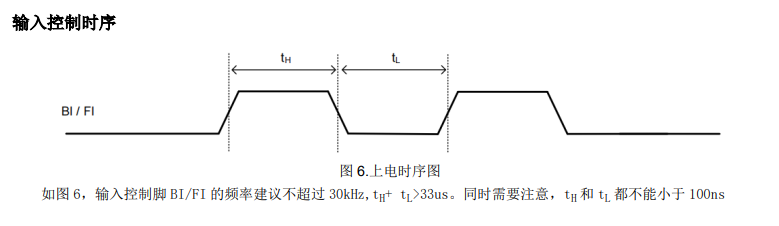 Previously, the RZ7899 datasheet didn't contain any description of PWM waves, leading me to believe that anything conforming to a similar input truth table would have similar performance. The image below shows the input truth table for the RZ7899, which is completely identical to that of the BDR6126D. (Surprised by the harsh realities of the market)
  A closer look at other motor driver chips from Bardin Microelectronics (the BDR6126D is one of their products) reveals clear indications that PWM input is possible, along with corresponding input control timing. This datasheet provides nothing; while PWM control is possible, it feels somewhat unprofessional.
 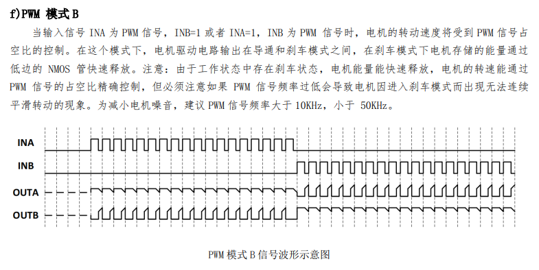 Changing the parameters in the PWM duty cycle function did not achieve the expected speed control effect. Adjusting the speed setting didn't significantly change the motor speed.
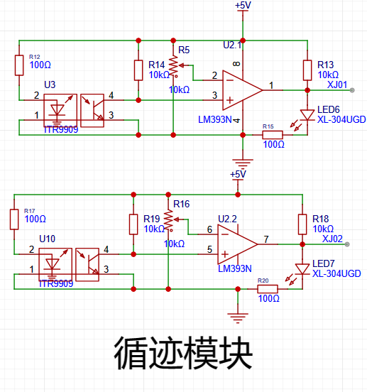
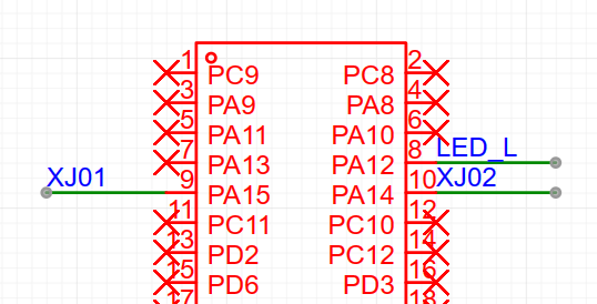
  However, in the pin assignment, LQ- is assigned to PB4, and PB4 is in pull-up mode after reset. Using the BDR6126D, after downloading the program and resetting, the left front wheel always rotates; continuously pressing the reset button will cause it to rotate continuously.


All reference designs on this site are sourced from major semiconductor manufacturers or collected online for learning and research. The copyright belongs to the semiconductor manufacturer or the original author. If you believe that the reference design of this site infringes upon your relevant rights and interests, please send us a rights notice. As a neutral platform service provider, we will take measures to delete the relevant content in accordance with relevant laws after receiving the relevant notice from the rights holder. Please send relevant notifications to email: bbs_service@eeworld.com.cn.
It is your responsibility to test the circuit yourself and determine its suitability for you. EEWorld will not be liable for direct, indirect, special, incidental, consequential or punitive damages arising from any cause or anything connected to any reference design used.
Supported by EEWorld Datasheet
EEWorld
subscription
account

EEWorld
service
account

Automotive
development
community

Robot
development
community

About Us Customer Service Contact Information Datasheet Sitemap LatestNews


Room 1530, 15th Floor, Building B,
No.18 Zhongguancun Street,
Haidian District,
Beijing, Postal Code: 100190
China
Telephone: 008610 8235 0740
 京公网安备 11010802033920号

 MAX6481BL30BD3


