Design Background:
This training camp focuses on designing and building a simple digital oscilloscope, which is highly beneficial for developing comprehensive abilities. Participants in this digital oscilloscope project will not only learn microcontroller circuit design and development, but also signal conditioning circuit calculations, human-computer interaction design, and enclosure model design, integrating knowledge of analog circuits, microcontroller design, circuit and PCB design, and enclosure design.
Function Description:
Basic Functions:
1. Signal Measurement
: Range 1: Measures input signal amplitude from -1.6V to 5V.
1/50 Range: Measures input signal amplitude from -80V to 250V.
Note: Can test AC or DC.
2. Signal Frequency Measurement
: Measures signal frequencies up to 100kHz; tested successfully.
3. PWM Signal Output
: Outputs 1kHz, 2kHz, and 4kHz square wave signals (duty cycle adjustable). The power supply
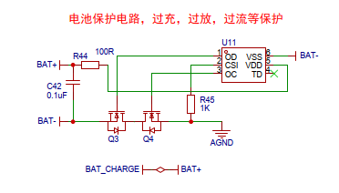
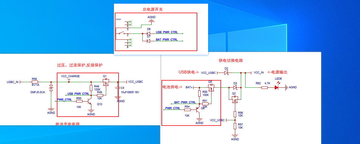
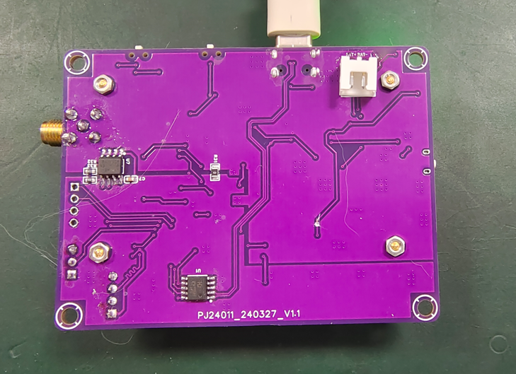
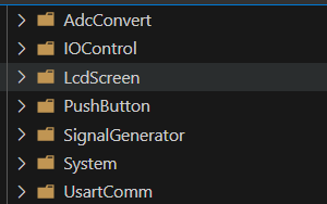
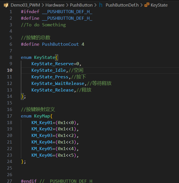
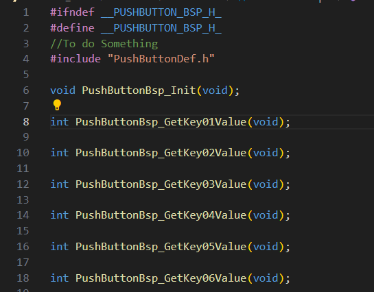
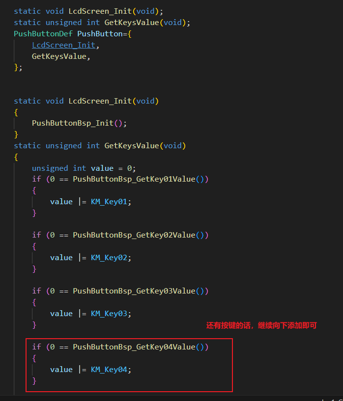
has been modified and innovated with the addition of overvoltage, overcurrent, and reverse connection protection. Battery protection, charging, and discharging circuits have also been added, making the oscilloscope more portable and eliminating anxiety about running out of power. A dual-power input (battery or external) switch has been added, allowing the oscilloscope to use battery power when there is no external input and external power when there is. A long-press power-on/power-off function has been added (the power-off function requires a jumper wire, which I forgot to draw at the time), meaning the microcontroller can control the power supply. A buck-boost circuit has been added to increase the external power input range and improve internal circuit stability. Battery voltage acquisition has been added (requires a jumper wire if the wiring is incorrect), allowing the oscilloscope to display the battery level and automatically shut down when the battery is low, in conjunction with the microcontroller. The PWM output has been expanded from one channel to two , and an EEPROM has been added to store user configuration information for loading upon next power-on. The screen has been upgraded from 2.0 inches to 2.4 inches with a resolution of 240*320, providing a better viewing experience. Other features include the removal of the coded switch and the replacement with five tactile buttons; retention of all functions of the GD32 core board, with all components being surface-mount and integrated onto a single board; and the replacement of the BNC connector with a smaller, more refined SMA connector. The schematic design includes output overvoltage, overcurrent, and reverse connection protection . R58 is a fuse, working in conjunction with a transient voltage suppressor diode to provide overcurrent and overvoltage protection. Q1 is a P-type transistor providing reverse connection protection. Battery charging (TP4065) and the familiar battery protection chip (DW01) are also common. The power supply switching circuit mainly consists of D2, D3, and Q2, but requires the external input voltage to be greater than the battery voltage. The button power on/off circuit is the part circled; the button directly controls the two MOSFETs Q1 and Q5, achieving the effect of power-on when pressed. After power is applied, the microcontroller indirectly controls the MOSFET through two transistors, Q8 (illustrated incorrectly here; it should be an NPN transistor like Q10) and Q10. When a button is pressed, the microcontroller takes over power control, allowing it to automatically power off. The circled area in the battery voltage acquisition diagram was drawn incorrectly and needs to be disconnected and connected to the battery's positive terminal with a jumper wire. This will be corrected in the next version. The voltage in the buck-boost circuit is not the standard 5V after the switching circuit; it may be lower. Furthermore, USB and other devices have significant ripple. Therefore, the voltage is directly buck-boosted to 7V before being converted to 5V and 3.3V by an LDO, making the subsequent circuits more stable and reliable. The subsequent storage circuitry is largely the same as the training project. Circuit Modification Instructions & Physical Demonstration: I've got a cat, so there's a lot of fur, please don't mind. I rewrote the program, but it's not completely finished. The program demonstration is shown below: Code Explanation: The code is written in modules, and the 2.4-inch screen driver has also been ported. The code structure is roughly the same. Which driver (button) code demonstration? 1. Button Definition 2. Button Hardware Driver Layer Header File: Source File : 3. Button Software Driver Layer Header File: Source File: 4. Call: Just call it directly. It's really convenient for future code reuse. If you have better ideas, we can discuss them together. Notes & Tips: To be updated later.


 京公网安备 11010802033920号

 61581-022HA


