I. Schematic Design Description
1. Analog Front-End Processing Circuit
(1) AC/DC Coupling Switching Circuit
Signal types can be divided into DC signals and AC signals. In reality, signals are often not ideal waveforms. For example, a DC power supply signal should be a horizontal DC signal, but there will be power supply ripple (AC signal); when collecting AC signals, DC signals may also be mixed in, affecting the peak-to-peak value of the waveform. In order to ensure accurate measurement of the input AC signal, the DC component in the signal can be filtered out by connecting the capacitor in series with the circuit using the characteristic of the capacitor to pass AC and block DC. This is the concept of AC coupling. DC coupling means that no processing is done on the input signal. The circuit switches the input AC/DC coupling signal through a toggle switch SW6. When switch 2 and 1 are connected together, it is DC coupling. When switch 2 is connected to 3, it is AC coupling.
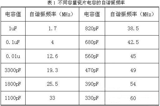
To solve this problem, it is necessary to understand the frequency characteristics of the capacitor. Ideally, the DC blocking capacitor should be as large as possible. However, due to the different self-resonant frequencies of different capacitance values, the capacitor exhibits a capacitive state below the self-resonant frequency and an inductive state above the frequency. The larger the capacitor, the lower its self-resonant frequency. Simply put, a large capacitor passes low frequencies and a small capacitor passes high frequencies. As shown in the upper right figure, when the ceramic capacitor is 0.1uF (100nF), its self-resonant frequency is 4MHz.
Generally, the cutoff frequency of the capacitor is required
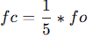
, where fo is the operating frequency in the circuit. Therefore, 100nF is sufficient for this project. However, if the input signal frequency is higher, a smaller capacitor should be selected.
(2) Input signal attenuation circuit
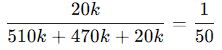
After the AC/DC coupling selection circuit, the input signal is selected by switch SW7 to select two channels. When switches 2 and 3 are connected together, the input signal flows directly into the voltage follower circuit of the next stage. When switches 2 and 1 are connected together, the input signal is attenuated to 1/50 times after passing through the voltage divider network composed of resistors R6, R12 and R15.
According to the calculation of the signal conditioning circuit,
when switches 2 and 3 of SW6 are connected together, the measurable input signal amplitude is -1.6V to 5V.
When switches 2 and 1 of SW6 are connected together, the measurable input signal amplitude is -80V to 250V.
Therefore, when the input signal amplitude is small, the low voltage range can be selected first. If the input signal amplitude is uncertain during measurement, the high voltage range can be used first. If it is within the low voltage range, the low voltage range can be used to obtain a more accurate measurement result, and the protection circuit can be protected at the same time.
(3) Signal Conditioning Circuit
The signal conditioning circuit includes a voltage follower and a signal amplification circuit composed of operational amplifiers. When analyzing this part of the circuit, it is necessary to understand the principles of virtual open and virtual short of operational amplifiers.
Virtual Open:
The input impedance of an ideal operational amplifier is infinite, but the input impedance of a real operational amplifier is finite. If a voltage is applied to the input terminal of the operational amplifier and the current is measured at the input terminal, the current reading will be close to 0, as if the internal operation of the operational amplifier is disconnected and no current flows in, but in reality it is connected. This phenomenon is called virtual open.
It can also be understood using Ohm's law. When the voltage is constant, the current is inversely proportional to the resistance. If the resistance is infinitely large, the current will be infinitely small and close to 0.
Virtual Short:
Virtual short will occur when the operational amplifier is in deep negative feedback, making the potentials of the two input terminals equal, as if the two input terminals are shorted together. It can be approximated as V+=V-.
In negative feedback, a part of the output signal of the operational amplifier is taken out and fed back to the input terminal. This feedback makes the voltage difference between the two input terminals (positive input and negative input) of the operational amplifier approach zero, and the voltages of the two input terminals are almost equal. Although the two input terminals of the op-amp are not electrically short-circuited, due to the negative feedback, the voltages at the two input terminals are almost equal, as if they were short-circuited; hence, this is called a virtual short.
a) Voltage Follower Circuit:
In the U5.2 chip, the op-amp's inverting input pin 2 is connected to the op-amp's output pin 1. Based on the op-amp's virtual short characteristic, V+=V-=Vout. According to the virtual open circuit principle, the operational amplifier's input impedance is relatively large, so the operational amplifier's forward input current is very small. The op-amp's output impedance is small, so the output current is very large. Therefore, the voltage follower here acts as an impedance matcher.
b) Proportional Amplifier Circuit:
When analyzing the circuit constructed by the U5.1 op-amp, it can be decomposed into a non-inverting proportional amplifier circuit and an inverting proportional amplifier circuit for separate analysis before combining them.
Assuming the op-amp's forward input terminal is grounded, forming an inverting proportional amplifier circuit, the current flowing into the op-amp from the inverting input pin is 0, so R13 and R15 can be considered as connected in series, and therefore the current flowing through them is the same. From the virtual short characteristic, we know that V+ = V- = 0. Therefore,
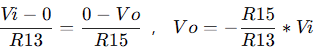
substituting Vi = 1V, R13 = 20KΩ, and R15 = 10KΩ, we get Vo = -0.5V, consistent with the simulation result.
Assuming the op-amp's inverting input is grounded, forming a non-inverting proportional amplifier circuit, the virtual short characteristic of the op-amp means the current flowing through the two input pins is 0, i.e., the current flowing through R4 is 0, Vin = V+. We can consider R13 and R15 as being in series, so the current flowing through them is also the same. From the virtual short characteristic, the voltages of the two input pins are the same, i.e., V+ = V-, therefore Vin = V+ = V-. Vo forms a loop with R13 and R15. The current flowing through it is:
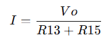
Considering R13 alone, the current is equal to the voltage across it divided by its resistance. Substituting this into Vin=V+=V-, we get the following formula:
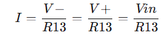
Combining the two formulas, we get:

Substituting Vin=5/3V, R13=20K, and R15=10K into the formula, we get Vo=2.5V, consistent with the simulation result.
Combining the above non-inverting and inverting amplifier circuits, we get the following formula: Substituting
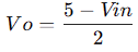
Vin=1 into the formula, we get Vo=2V, consistent with the simulation result.
The Vo signal will be directly connected to the ADC pin of the microcontroller. Since the microcontroller acquires the ADC voltage range of 0~3.3V, the input voltage range of the oscilloscope can be calculated.
When the input signal Vin does not decay, substituting Vo=0 and Vo=3.3V into the formula respectively, we get:

When the input signal Vin decays by 1/50, substituting Vo=0 and Vo=3.3V into the formula respectively, we get:
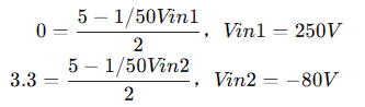
We get the following conclusions:
Low voltage range measurement range: -1.6V~5V, high voltage range measurement range: -80V~250V
(4) Comparator frequency measurement circuit
In order to realize the frequency detection function, the ADC input signal is compared with the input signal through a hysteresis comparator to realize the frequency measurement function. The hysteresis comparator is a type of voltage comparator. The conventional voltage comparator is a single-threshold comparator. There is only one threshold voltage in the circuit, but when the input voltage changes slightly near the threshold, it will cause the output voltage to change. In order to enhance the anti-interference capability of the circuit, positive feedback is introduced on the basis of the single-threshold comparator to ensure the stability of the signal within a certain range. After passing through the hysteresis comparator circuit, a square wave signal is output. The period of the input waveform is calculated by using the timer capture function of the microcontroller.
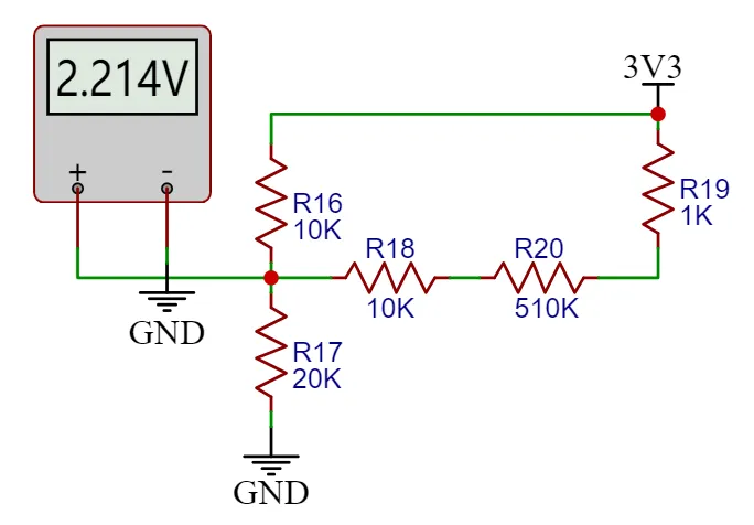
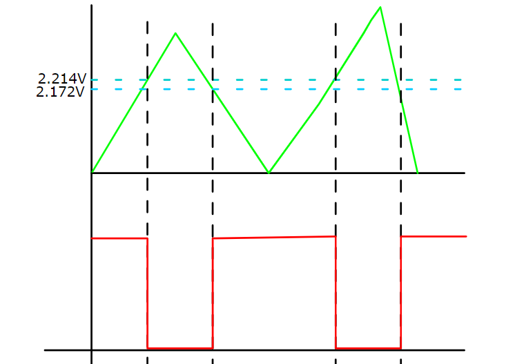
The threshold voltage of the hysteresis comparator circuit needs to be analyzed separately based on the op-amp output. When the output is high, the output terminal is pulled up to a high level, and the equivalent circuit is shown in the left figure below. We calculate Uth = U+ = 2.214V. When the op-amp output is low, the output terminal is grounded, and the equivalent circuit is shown in the right figure below. We calculate Utl = U- = 2.172V. The
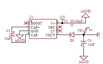
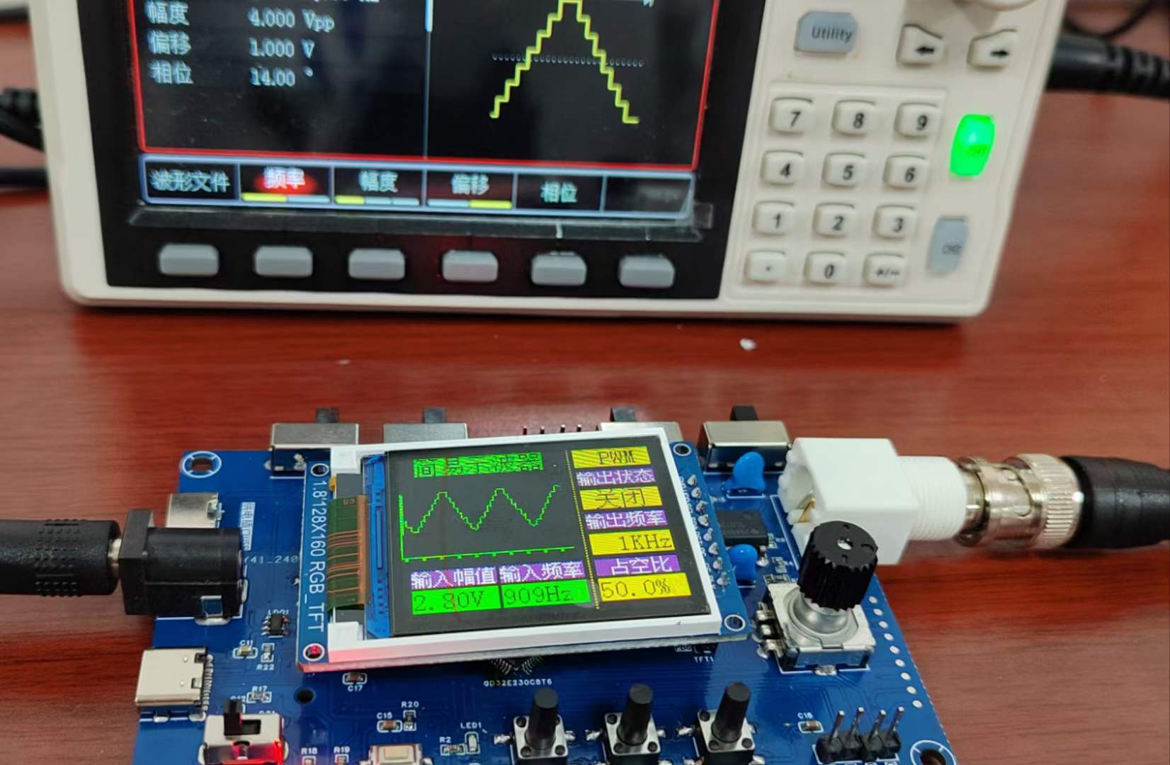
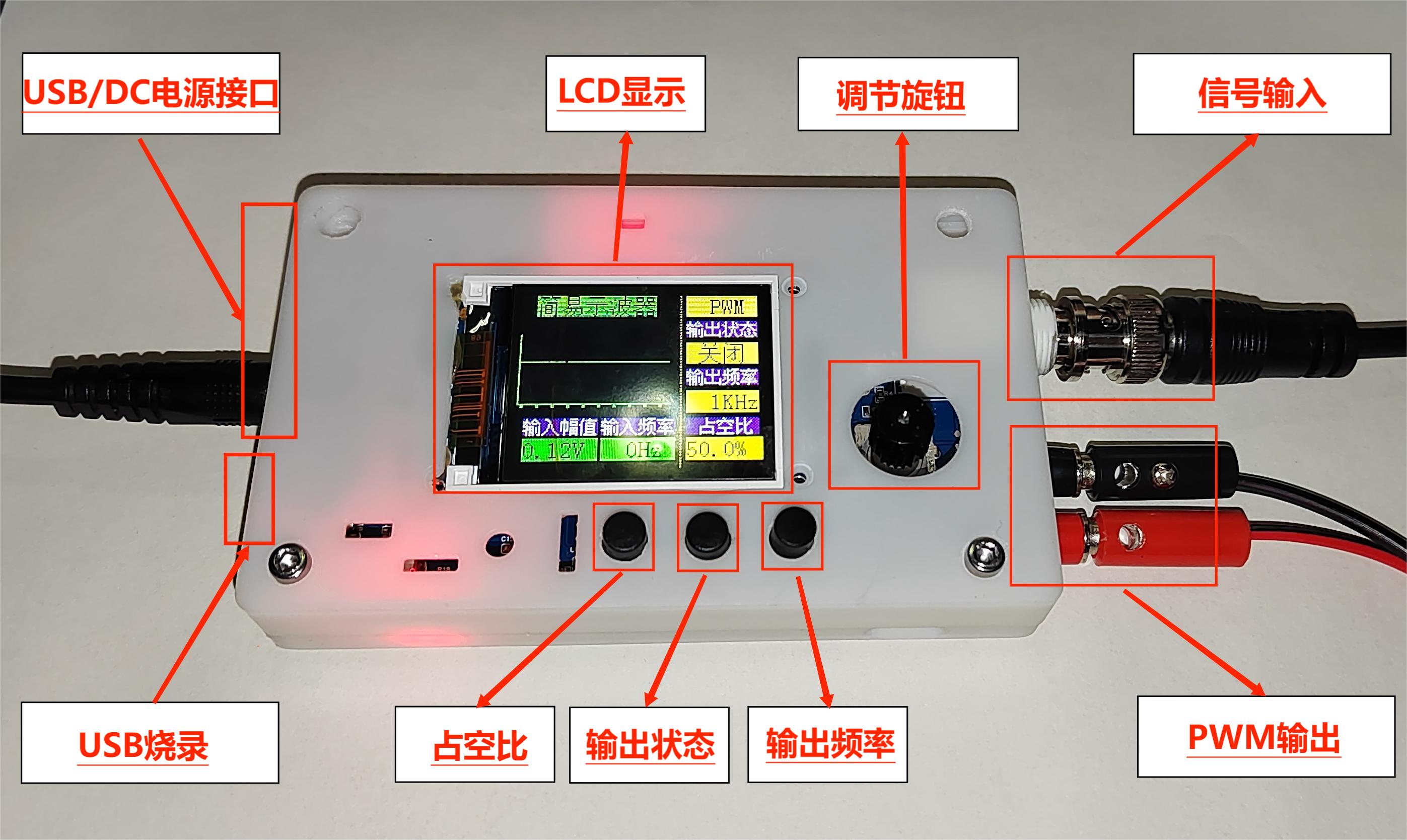
green line in the diagram below represents the change in the signal input voltage. Starting from 0 potential, the initial output state is high. When the input voltage reaches 2.214V, the output signal becomes low, until the input signal falls below the lower threshold of 2.172V, at which point the output becomes high again. The threshold for the next level change can be determined based on the current output state of the comparator. When the output is high, the high threshold Uth is used; when the output is low, the low threshold Ttl is used. The reason for setting the thresholds close together is to avoid misidentification caused by signal interference. 2. Power Control Circuit: This project uses the GD32 as its core, with an onboard 5V to 3.3V step-down circuit. Therefore, only a 5V power input circuit needs to be designed when designing the expansion board. The mainstream Type-C and DC input interfaces are chosen, and this interface has only two wires and is a plug-in package, making it easy for beginners to learn soldering. However, it should be noted that this Type-C interface is only for power supply and cannot transmit data. If data transmission is required, a second Type-C interface can be used. SW2 is the port switching switch, SW3 is the main power switch, C2 is the input filter capacitor, and R1 is the current-limiting resistor for LED2. In addition to the power input circuit, to ensure the operational amplifier's performance in measuring negative voltages, an XD7660 negative voltage generator circuit is used to obtain a negative voltage. This chip has a simple external circuit, requiring only two capacitors and one diode to operate. Theoretically, with an input voltage of +5V, it can also output a -5V voltage. Due to the chip's internal voltage drop and conversion efficiency, the actual measured negative voltage is approximately -4.3V, which still meets the requirements of the operational amplifier. 3. Microcontroller Circuit The microcontroller circuit uses the GD32 minimum system board circuit launched by the LCSC development board team. I personally prefer to integrate the circuit onto one board. The GD32 chip costs a little over one yuan and is very cheap on Taobao. It can also be modularly designed, which is simpler and more convenient. 4. Human-computer interaction circuit (1) LCD screen display circuit 1.8 TFT is a color display screen with 128 x 160 color pixels. It uses four-wire SPI communication to connect with the microcontroller. I bought it on Taobao. I heard from a group member that I lost a few yuan because I didn't get a discount. I am heartbroken! (2) Rotary encoder circuit The rotary encoder is a special kind of button. The EC11 rotary encoder used in this project has five pins. Among them, the DE pins are similar to ordinary button pins. They are turned on when pressed and turned off when released. The other three pins ABC are used to detect the rotation direction of the knob. The C pin is the common terminal and can be directly grounded. In the rotary encoder, there is a phase difference between the two signal pins A and B. That is, after the signal of one pin changes, the signal of the other pin changes accordingly. That is, the two pins do not change at the same time. By detecting which pin changes first, it can be determined whether it is a forward or reverse function. (3) LED indicator circuit The LED indicator circuit design is relatively simple. It adopts a low-level driving method. When the output of the microcontroller pin is low, there is a potential difference between the two ends of the LED, and the LED lights up; when the output of the microcontroller pin is high, the LED turns off. I am a complete novice and can also drive the LED with a transistor. (4) Key input detection circuit In addition to the rotary encoder, this project also uses three independent keys to control the system. One side of the three keys is directly grounded, and the other side is connected to the microcontroller pin. When the microcontroller pin detects that the key is pressed, the microcontroller pin is directly connected to GND ground. After receiving the feedback of the grounding signal of the pin, the microcontroller implements the corresponding function. In order to save hardware costs, a debouncing function can be introduced in the software design to avoid false triggering when the mechanical key bounces. The complete technical documentation for the training camp can be found at: https://www.yuque.com/wldz/jlceda/dso?singleDoc II. Software Design GD32E230C8T6 LCSC official introductory materials Baidu Cloud link: https://pan.baidu.com/s/105CYcL5jc5wnMoSi9HnDlQ?pwd=c8t6 Extraction code: c8t6 - Baidu Cloud link: https://pan.baidu.com/s/105CYcL5jc5wnMoSi9HnDlQ?pwd=c8t6 Extraction code: c8t6 Introductory Tutorial https://lceda001.feishu.cn/wiki/Tlp5wNmPii2oKekezjpcCeA7ndh The complete oscilloscope code is in the attachment; software design technical documents can be found in the official tutorial https://www.yuque.com/wldz/jlceda/dso?singleDoc III. PCB Design Description I'm also a novice in PCB design, and what I drew is barely usable. My ADC cable was a bit too long, but fortunately, there weren't any major problems. Physical verification showed that the basic functions were fine. IV. Physical Demonstration Soldering I brought out my veteran, a yellow 907 that has been with me for three years. It was also my first soldering iron when I started learning electronics. Many of my boards owe their success to it; surface mount resistors and MCUs were directly soldered with solder paste + hot plate/hot air gun. Since I manually applied the solder paste one by one with a syringe, I later corrected the solder joints with the soldering iron when troubleshooting. I usually use 0805 chips for surface mounting, but this time I mostly used 0603 packages, with a few 0805s and one large 0R resistor. Before powering on, I always check for solder bridging and reversed electrolytic capacitors, ensuring all components are soldered correctly before powering on. I changed the BOOT switching mode to a switch, adjusted the BOOT switch, and then used a USB cable to connect and program the Type-C port (or ST-Link, etc.). After adjusting the BOOT switch and pressing the reset button, the display and waveform measurements worked correctly. The problem was that the PWM output switch button functioned the same as the frequency adjustment button. (After troubleshooting, I resoldered the MCU, and the problem was solved. It was probably due to the probe being too thick and too much solder paste causing solder bridging in some areas.)


Problem solved. Powering on and reconnecting the signal generator, other functions tested fine. Started working on the casing and panel...
Currently, I haven't thought of a better solution for these two lines. The best approach is to redesign the PCB, but time is limited, so I'll make do for now.


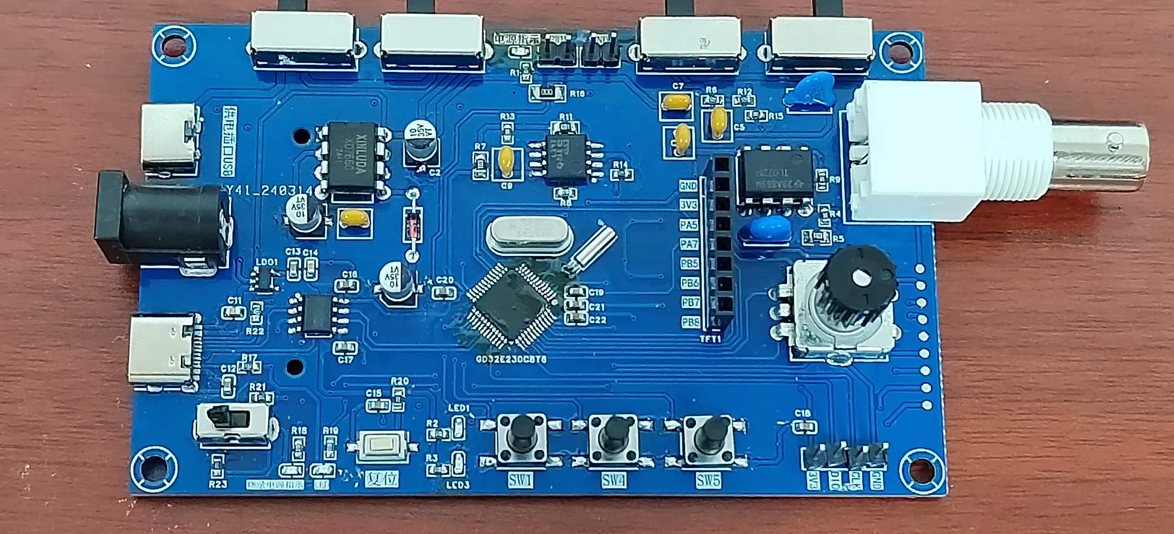
The final physical product looks like this; there's no panel yet, and the design is a bit rough, please forgive me.
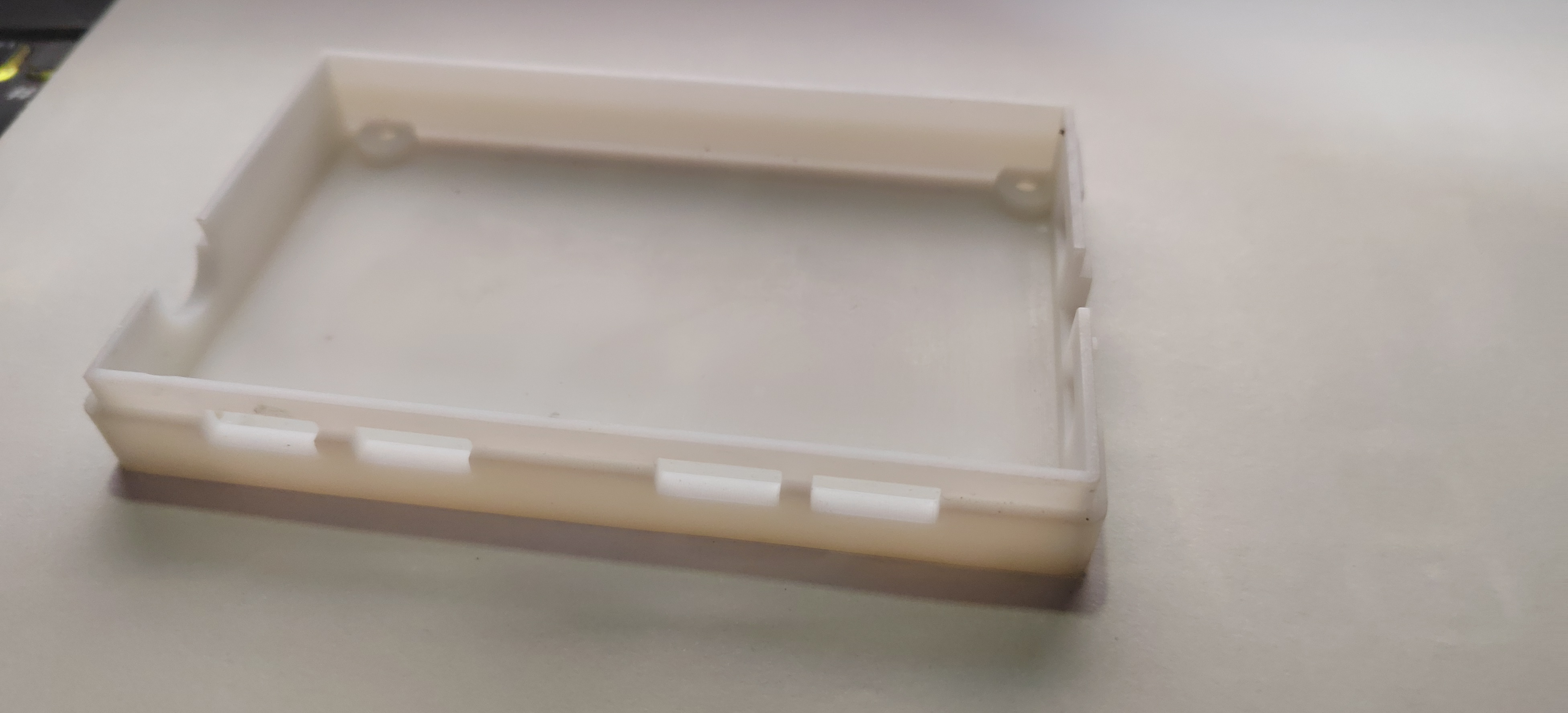
V. 3D Casing Printing :
Top Board ,

Bottom Board, First Version,

Bottom Board, Second Version: Added ribbon cable grooves and PWM output interface holes.
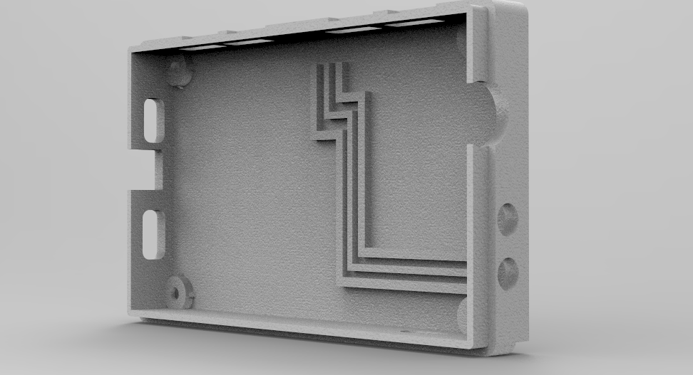
For the second version of the bottom board
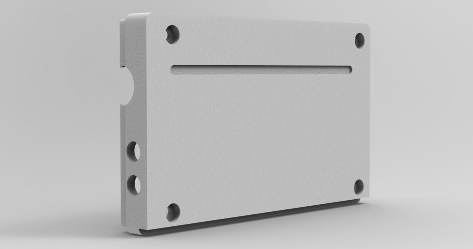
, JLCPCB's 3D Monkey was the first choice for printing the back; the casing printing effect is very good.
Currently, we're still missing modeling for a knob cap and some small parts like switch caps, which we'll work on later when we have time.
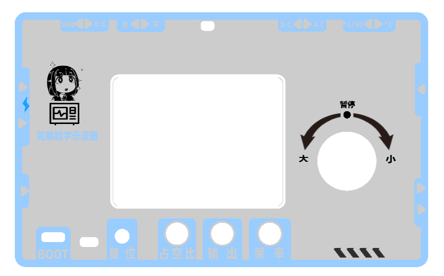
VI. Panel Design:
The cutout positions haven't been fine-tuned; it's just a rough color scheme and appearance design. We'll adjust it according to the casing parameters and then verify it with a physical prototype.
We tried several color schemes and pattern element placements during the design process, and this scheme is currently finalized. (For reference only)
VII. Precautions :
1. Pay attention to whether there are any omissions in the schematic design and whether the component selection or replacement is reasonable.
2. Pay attention to PCB design considerations and signal routing.
3. Pay attention to component soldering issues such as cold solder joints and the presence of short circuits or open circuits.
4. Pay attention to the casing dimensions and cutout dimensions.
VIII. Summary
This training camp provided an initial glimpse into the design of a simple oscilloscope. I gained a lot from the circuit schematic, PCB design, and actual implementation processes. Through continuous exchange with excellent designers, I learned from their strengths and improved my weaknesses. I also thank the engineers at JLCPCB for their hard work and for providing such a platform and activity for learning and exchange. During the design and manufacturing process, I continuously corrected my own shortcomings and cultivated good design habits. Let's strive together, and wish all excellent designers and developers bug-free design.
IX. Demonstration Video


 京公网安备 11010802033920号

 SMCJ26A


