1. Project Introduction: This project
involves designing and improving upon a simple oscilloscope based on LCSC's open-source platform. The main additions include a soft-start function, battery charging management, a buzzer notification, and a DS18B20 temperature detection function. During use, a disabling control pin is activated when low voltage is detected to prevent battery damage from excessively low discharge. Although there were previous hardware and software code examples, several problems were encountered during actual debugging, such as insufficient hardware checks leading to the need for jumper wires. Below is a brief introduction to my modified layout and software code.
Note: Although it's a simple oscilloscope, it's found to be sufficient for learning purposes. However, when using it in a working environment, the input voltage should not exceed 12V. The input voltage can be attenuated based on your usual working voltage. Do not use this oscilloscope to test high voltages (AC 220V). I replaced the original through-hole components with surface-mount components, which also saves board space.
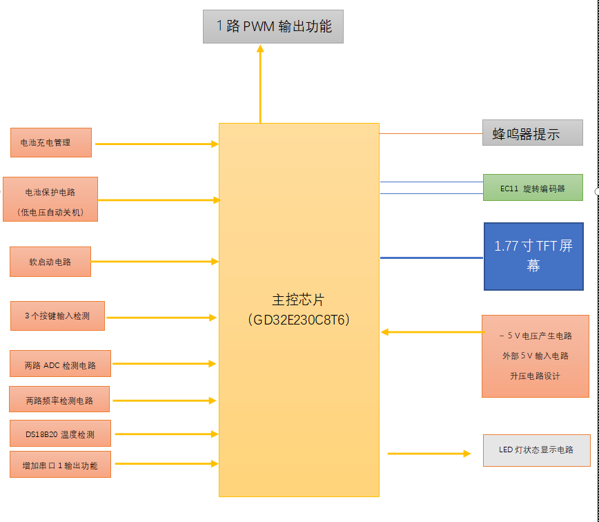
2. Hardware
Architecture
2.1 Soft-Start Circuit
PS7516 Chip Introduction: The PS7516 (5V1A Synchronous Rectification Boost Chip) is used as the boost chip. The PS7516 is a high-efficiency original manufacturer lithium battery synchronous rectification boost IC designed specifically for 5V1A applications. This IC employs advanced synchronous rectification technology. Compared to the diode rectification used in traditional power conversion processes, the PS7516 replaces the traditional diode with a built-in high-performance MOSFET, achieving highly efficient conversion in the rectification stage, thereby reducing voltage drop and heat loss, and significantly improving power conversion efficiency. The PS7516 has excellent thermal stability and over-temperature protection. In high-temperature environments, this IC can automatically reduce output power to prevent overheating damage and ensure stable system operation. When the chip temperature exceeds the preset safety value, the over-temperature protection function will automatically activate, shutting down the IC's output to protect the lithium battery and system from damage. Furthermore, the PS7516 features fast transient response, making it suitable for various applications requiring rapid response. The chip also features a space-saving SOT-23-6 package for easy integration in portable applications. In summary, the PS7516 is a high-performance, feature-rich lithium-ion battery synchronous rectification boost IC that meets the needs of various application scenarios, providing an efficient and reliable solution for power management of electronic devices.
Output voltage calculation: Vout = 0.8 * (1 + (R15 + R18 + R19/R20)).
PCB layout recommendations: Add 100nF filter capacitors at the input and output terminals to eliminate noise interference. Input and output capacitors, inductors, and other electrical connections should be as close to the IC chip as possible. Use thicker connecting wires and keep them on the same layer as much as possible. A large ground plane is needed to reduce ground noise.
Software design approach: A physical button is used to turn on transistor Q1 (NPN type). This allows the PS7516's enable pin to input the battery voltage (Vbat), which in turn enables the microcontroller's control pin PA11 (POWER_CTRL) to output a high level, keeping the transistor constantly conducting. This ensures the PS7516 remains operational. One-third of the battery voltage is input to the ADC detection pin of the GD32E230. When the battery power is low, the microcontroller's output pin is directly shut off to protect the battery. This function will be demonstrated later in the video.
To prevent damage to circuit components from reverse battery connection, a U7 (1N4148) is installed in the hardware design for circuit protection.

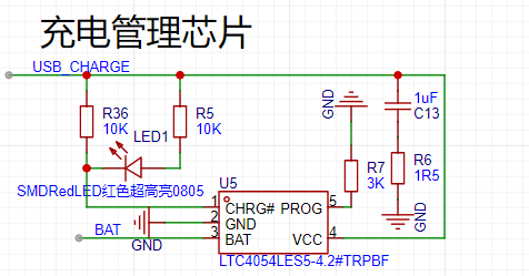
2.2 Charging Circuit Design
The LTC4052 is a complete constant current/constant voltage linear charger for single-cell lithium-ion batteries. Using an SOT23-5 package, it requires only external resistors and capacitors to operate normally, making it a chip specifically designed for operation within the USB power specification.
Because the chip uses an internal MOSFET architecture, it does not require external sense resistors and isolation diodes. Thermal feedback can regulate the charging current to limit the chip temperature under high-power operation or high ambient temperature conditions. The charging power supply supports a maximum input of 10V, and the charging current can be externally set using an external resistor. When the charging current drops to 1/10 of the set value after reaching the final floating voltage, the charging chip will automatically stop charging.
When the input voltage is 0, the chip automatically enters a low-current state, reducing the battery leakage current to 2µA. The LTC4052 can be put into a shutdown state, thereby reducing the supply current to 25µA. The chip also features a charging current monitor, undervoltage lockout, automatic charging, and a status pin for charging completion and input voltage connection.
Setting the charging current here only requires changing the resistor at R7.
Resistor values of
10K
, 3K
, 2K
, and 1.65K correspond to
charging currents
of 100mA,
300mA,
500mA, and
600mA.
Here, I chose a 3K resistor value. Of course, the charging current should not be set too high; try not to exceed 500mA. The charging current is not only related to the designed resistor value but also to the current battery level. When the voltage is low, the charging current is higher and charging is faster. When the battery voltage exceeds 4V, the charging current becomes very small. This is normal, and you don't need to worry too much about the charging current.
2.3 Type-C Interface and Battery Interface
To ensure the input USB 5V voltage and the voltage boosted by the PS7516 are compatible, an input voltage selection function was added. By toggling a potentiometer, the input voltage can be used for system power supply or battery charging. To minimize battery leakage current when not in use, a jumper cap was installed. When the battery is not in use for an extended period, the connection between the battery and the circuit board can be disconnected, preventing leakage current due to external circuitry and extending battery life.

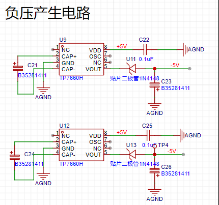
2.4 Negative Voltage Circuit
To ensure the operational amplifier functions correctly, a TP7660H charge pump voltage inverter manufactured by Nanjing Tuowei Integrated Circuit Co., Ltd. was selected.
The TP7660H is a dedicated integrated circuit for DC/DC charge pump voltage inverters. The chip can convert an input voltage range of 2.5V to 11V into a corresponding output of -2.5V to -11V, requiring only two external capacitors and eliminating the need for an inductor, thus reducing losses, area, and electromagnetic interference. This chip has low no-load current and strong drive capability (50% greater than similar foreign products).
Product Features:
• Wide input voltage range; • High voltage conversion accuracy; • High power conversion efficiency; • Low power consumption: no-load current is
40uA (at 5V input), 99.9% to 98%; • Low output resistance: 50Ω (at 5V input);
• Few external components, easy to use: only two external capacitors required
; • High electrostatic breakdown voltage:
up to 3KV.
Limiting parameters: Power supply voltage 11.5V, power consumption SOP-8 470mW, operating temperature TA -40℃ to 125℃, wire soldering temperature (10 seconds) 260℃.
This chip supports parallel circuitry: to reduce output resistance, TP7660 chips can be connected in parallel, which can be understood as improving the output drive capability and reducing the impact of output resistance. Circuit cascading: can generate higher output negative voltage; due to the limited power efficiency of a single chip, the number of cascaded chips in practical applications is also limited. In this case, the output resistance is approximately n times the resistance value of each chip (n is the number of cascaded chips).
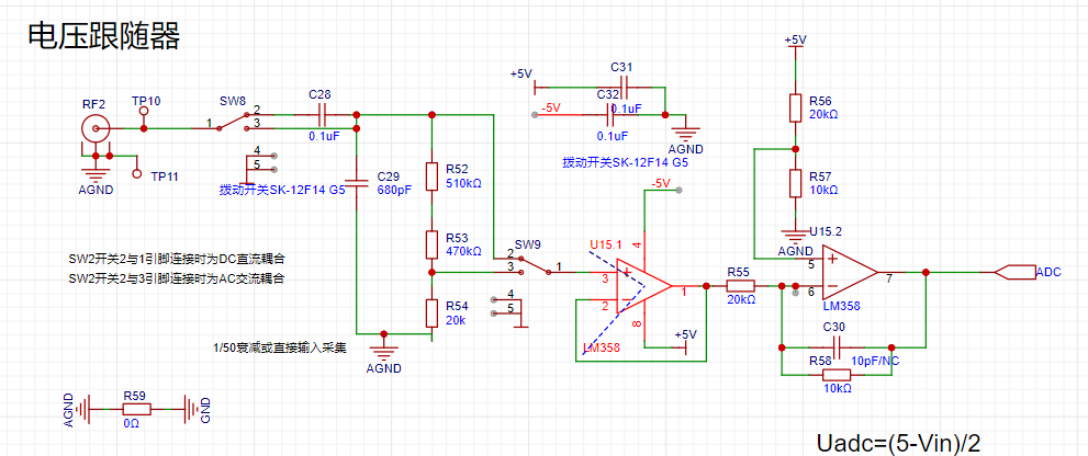
2.5
LM358 Operational Amplifier Circuit The
LM358 is a dual operational amplifier. It internally includes two independent, high-gain, internally frequency-compensated operational amplifiers, suitable for single-supply use with a wide power supply voltage range, and also suitable for dual-supply operation. Under recommended operating conditions, the supply current is independent of the supply voltage. Its applications include sensor amplifiers, DC gain modules, and all other applications where operational amplifiers can be powered by a single power supply.
Chip Features
: 1. Internal frequency compensation; 2. High DC voltage gain (approx. 100dB); 3. Unity-gain bandwidth (approx. 1MHz); 4. Wide power supply voltage range: single power supply (3-30V); 5. Dual power supply (±1.5V to ±15V); 6. Slew rate (0.3V/µs), low power consumption current, suitable for battery power; 7. Low input bias current, low input offset voltage and offset current; Wide common-mode input voltage range, including ground;
8. Wide differential-mode input voltage range, equal to the power supply voltage range; 9. Large output voltage swing (0 to Vcc-1.5V).
I didn't choose other operational amplifiers, such as the TL2072 chip. Although it performs better than the LM358, it's really expensive, around 10 RMB per chip, and that's from the PCB manufacturer. Cheaper ones on Taobao, but the quality can't be guaranteed. So, I still recommend choosing domestically produced operational amplifiers in the future.
2.6 Comparator Circuit:
The LM393 is a dual voltage comparator integrated circuit.
The output load resistor can be connected to any power supply voltage within the permissible power supply voltage range, without being limited by the Vcc terminal voltage. This output can function as a simple SPS open circuit to ground (when the load resistor is not used),
and the trap current of the output section is limited by the available drive and the β value of the device. When the limit current (16mA) is reached, the output transistor will exit and the output voltage will rise rapidly. In this design, I added a data acquisition channel to the existing pulse and frequency detection channel. The LM393 is dual-channel, and to avoid interference between the two channels during use, I added an LM393 as a precaution. This chip is not expensive, and adding one did not significantly increase the cost. However, during debugging, I found that I had overthought it; using dual channels is perfectly fine.

2.7 Serial Port 1 Output Circuit Introduction:
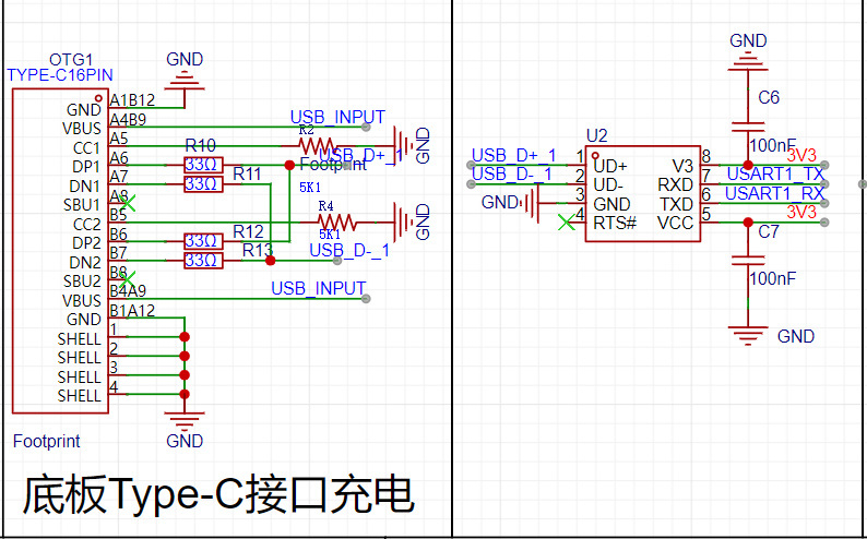
The function of Serial Port 1 is brought out for serial data export, separate from Serial Port 0, thus better utilizing the onboard resources.
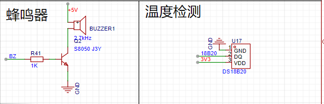
2.8 Other Circuit Introduction:
Here, I added a buzzer circuit and a DS18B20 detection circuit.
The buzzer is added primarily to provide a prompt when the button is pressed again. Sometimes, pressing the button doesn't produce the desired test effect, making it unclear whether the button wasn't pressed or if there's a software code issue. The buzzer alert helps determine if the button was triggered.
The DS18B20 digital temperature sensor provides 9-bit to 12-bit temperature measurement accuracy and features non-volatile, user-programmable upper and lower trigger point alarms. The DS18B20 communicates via a single bus, requiring only one data line (and ground line) to communicate with the microcontroller.
3: 3D Shell Design
I directly used LCSC EDA's 3D shell design software. Since this was my first time designing a 3D shell, I watched several tutorials on Bilibili, reviewing the software operation steps and design considerations. Overall, the design is rather rudimentary. The 3D shell software is incredibly powerful, even for someone with zero experience. The image below shows the result after two hours of learning, but it's usable for personal use.
However, this experience makes me think that designing a shell for a development board in the future would be much more enjoyable.
For those interested in learning 3D shell design, simply search on Bilibili; the explanations are very detailed.
3D and PCB renderings are shown below:

4: Software design
is straightforward; it involves adding to the source code. Those interested can discuss it privately. During debugging, I encountered some issues adding ADC acquisition, which were successfully resolved with guidance from experts. Using the same timer for frequency detection, just with different channels, I wasted time during debugging due to improper pin soldering.
5: Physical product images:

6: EDA participation experience:
1: I modified the original single-channel waveform detection to a dual-channel frequency detection function, which can be displayed on a 1.77-inch TFT screen, providing more options during equipment debugging. During debugging, I discovered that multiple ADCs could be acquired and processed simultaneously. Initially, I didn't carefully read the manual and used a polling method for acquisition, which wasted CPU resources and caused delayed screen refresh. With guidance from experts, I discovered that simultaneous detection was possible.
2. While debugging the soft-start circuit, I discovered a problem with my hardware design. During the software DRC detection, I didn't carefully review the circuit design, which led to a significant waste of time debugging the code. It's also possible that I was in a rush to build the board and didn't notice the issue until during debugging.
3. By participating in this training camp, I learned to use EDA 3D design software to design a shell for my board. Since it was my first time designing a shell, I lacked experience. I solved problems I encountered by learning through Bilibili and searching for solutions on Baidu.
4. Searching for chip information directly on the LCSC website was quite convenient. When encountering difficulties, I consulted the experts in the group; there are still many kind people in the world.
7. Demo Video:
Below is the Bilibili video link. If you've seen this far, please give it a like on Bilibili.
https://www.bilibili.com/video/BV1DZ421q7JW/


 京公网安备 11010802033920号

 IDT7285L15PAI


