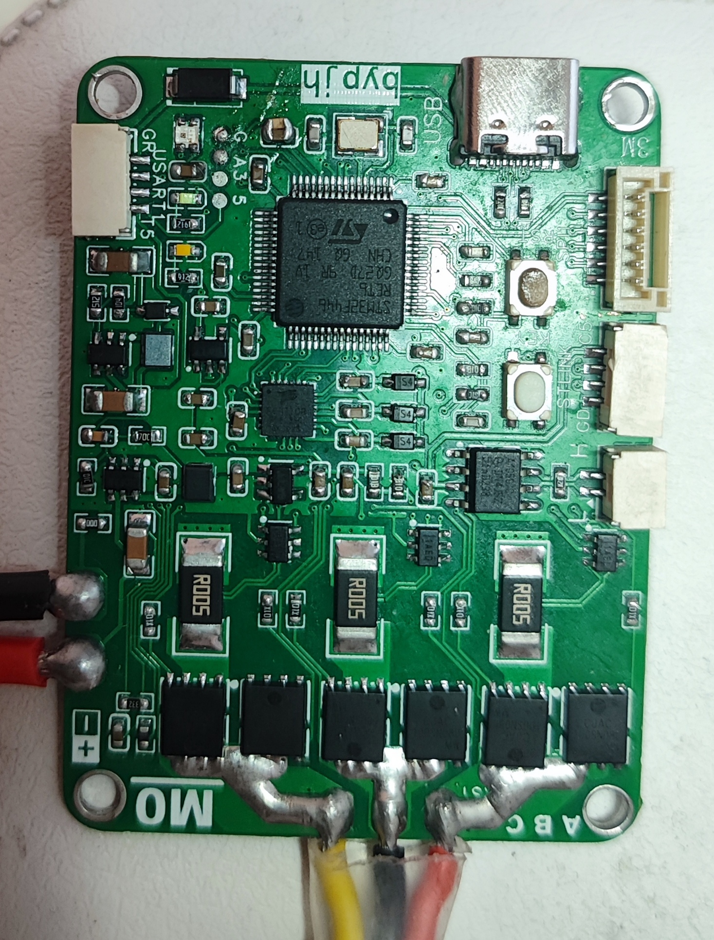
This is a simple FOC driver board that I made in my spare time. Due to my limited abilities, I only implemented basic open-loop speed control, dual closed-loop speed and current control, and triple closed-loop position, speed, and current control. The code isn't very good, so please be kind in your comments. Therefore, this project is only for reference and learning.
Speed closed loop.mp4
Location closed loop.mp4
STM32F446FOCV1.zip
User Manual.docx
PDF_FOC Control Learning Board Based on STM32F446.zip
Altium_FOC Control Learning Board Based on STM32F446.zip
PADS_FOC Control Learning Board Based on STM32F446.zip
BOM_FOC Control Learning Board Based on STM32F446.xlsx
96090
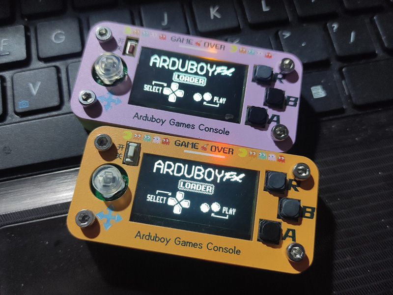
The first Arduboy copy in 2024
The 32U4-AU and MU chips are compatible, but the power-on/off chip has been changed to EC190707.
This is a clone of the project https://oshwhub.com/15653072438poiu/arduboy-fish-artifact.
The main modification is the power-on/off chip, which is easier to find on Taobao. The chip has been modified to be compatible with both 32U4-AU and MU. Use whichever you prefer!
Only the bottom shell needs to be printed; the top shell uses LCSC panel printing.
For instructions on how to use it, please refer to the original author's project; it's very comprehensive!
I've already made two. One uses an SSD1306 screen, and you can play it by uploading the original author's game collection—very convenient!
The other one uses a cheaper SH1106 screen, so the game collection doesn't work. You need to download the Arduboy game source code online and compile it yourself. When compiling, select the SH1106 screen to play it normally! This one is a bit more complicated to use, as you need to create your own game collection. I've already compiled over ten games! The attached file is my small collection.
PS: I discovered that Arduboy also supports the SSD1309 screen, and this screen has a large 2.4-inch display. I've decided to design a larger version of Arduboy after the Chinese New Year!
SH1106 small collection and py files.zip
PDF_The first Arduboy copy of 2024.zip
Altium_2024's first Arduboy copy.zip
PADS_2024 First Arduboy Copy.zip
BOM_2024 First Arduboy Copy.xlsx
96093
TB6612 motor drive module
The TB6612FNG is a popular motor driver IC widely used for controlling DC motors and stepper motors. It is favored for its high efficiency, low heat dissipation, and small size. The TB6612FNG can drive two DC motors or one stepper motor.
The TB6612FNG motor drive module is a high-efficiency motor drive solution based on the TB6612FNG integrated circuit (IC), specifically designed for controlling small DC motors and stepper motors.
Engineering Principles:
The TB6612FNG module primarily relies on its internal H-bridge circuitry to control the motor. An H-bridge is a circuit configuration that allows current to flow in either direction, enabling forward and reverse rotation control of the motor. The TB6612FNG contains two such H-bridges, allowing it to drive two DC motors or one bipolar stepper motor simultaneously.
The module uses low-resistance MOSFETs as switching elements, significantly reducing power consumption and improving efficiency. Furthermore, the TB6612FNG integrates over-temperature protection and undervoltage lockout functions to protect the circuitry from damage.
Function :
The main function of the TB6612FNG motor drive module is to control the motor's start, stop, forward and reverse rotation, and speed regulation. It can be used in various applications requiring motor control, such as robots, automated equipment, and toy cars.
Operating Conditions
: Power Supply Voltage: The TB6612FNG can operate from a power supply voltage of 4.5V to 13.5V, adapting to projects with different voltage requirements.
Output Current: Each channel can provide a maximum continuous drive current of 1.2A and withstand peak currents up to 3.2A.
Temperature: The operating temperature range is typically -20℃ to 85℃, meeting the requirements of most environments.
PDF_TB6612 Motor Drive Module.zip
Altium_TB6612 motor driver module.zip
PADS_TB6612 motor driver module.zip
BOM_TB6612 Motor Driver Module.xlsx
96094
esp8266_Control
The ESP8266-based power control board
controls four USB power switches,
supports brightness detection
, web control and button control,
and Wi-Fi networking. It can be
programmed using ESPHOME and integrated
with Homeassist .
The ESPHOME code has been uploaded to the Gitee repository: https://gitee.com/norep/hass_manager/blob/master/esphome/esp8266-control.yaml.
This ESP8266-based power control board controls four USB power switches, supports brightness detection, web control and button control, and Wi-Fi network configuration. It can be programmed using ESPHOME and integrated with Homeassist.

PDF_esp8266_Control.zip
Altium_esp8266_Control.zip
PADS_esp8266_Control.zip
BOM_esp8266_Control.xlsx
96095
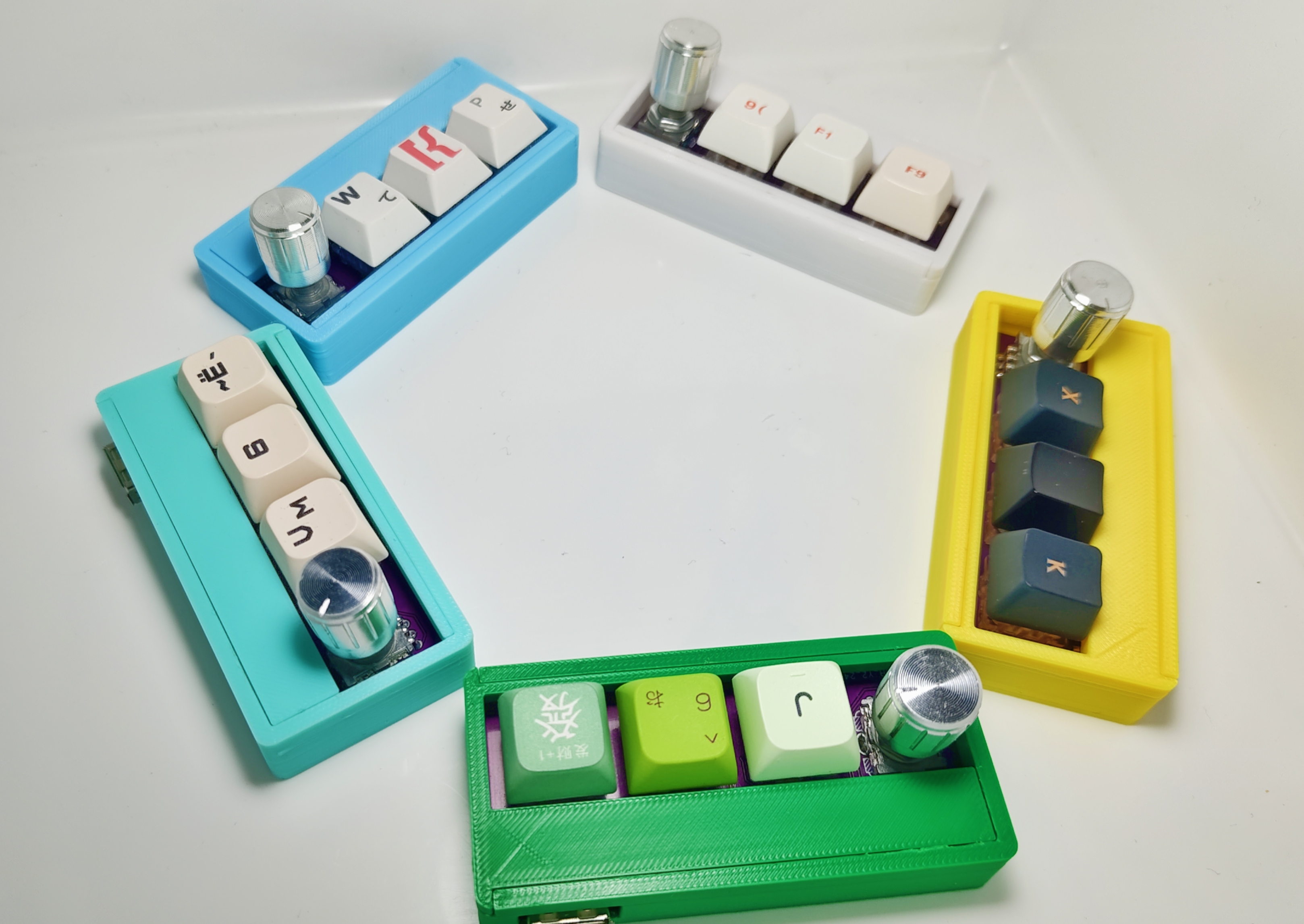
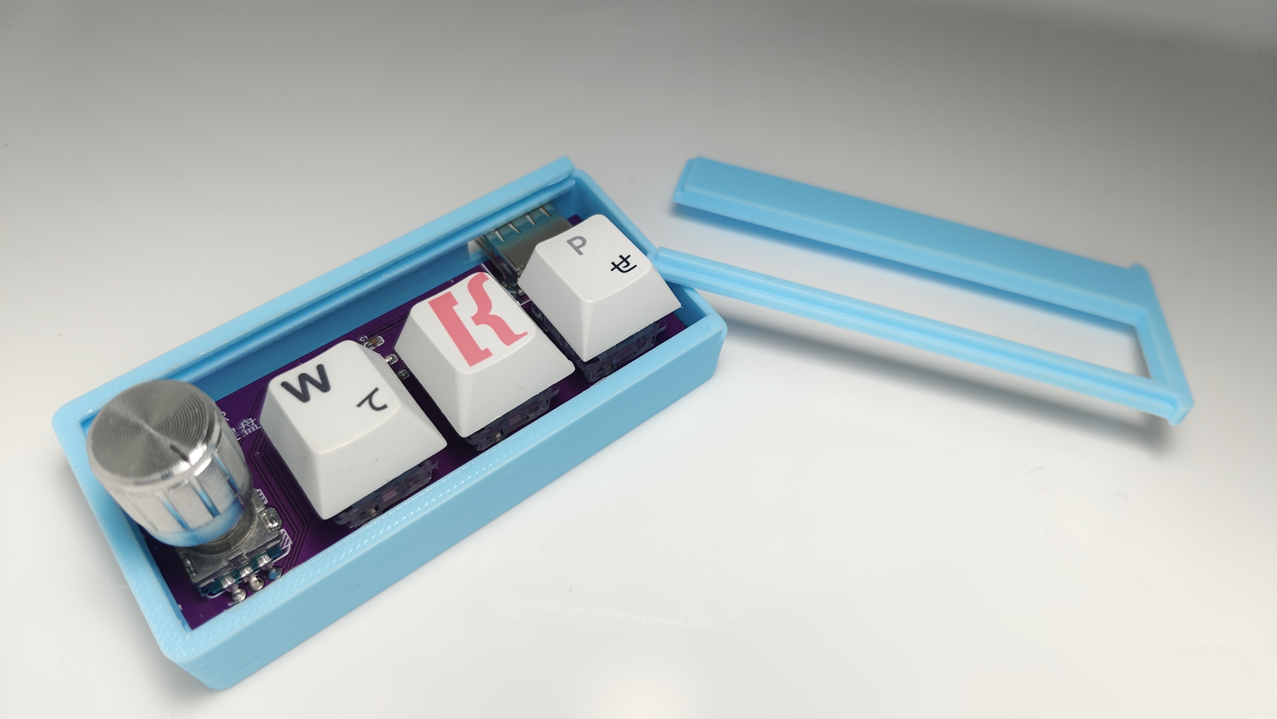
The CH552G numeric keypad features hot-swappable switches and RGB lighting.
This keyboard features a rotary knob and is based on the CH552G microcontroller. It uses Kailh hot-swappable keycap connectors, has a WS2812B LED on the bottom, and uses an EC11 encoder with built-in buttons. Onboard buttons are used for firmware programming. The casing is based on the 3D design of the JLCPCB EDA Professional Edition.
The engineering design references the open-source project by TheLight: https://oshwhub.com/TheLight/zi-ding-yi-jian-pan
Physical images:
Demo video:
[Open Source] Let's DIY a multi-functional keyboard with custom key layout, hot-swappable switches, and RGB functionality_Bilibili_ The
demo board designed by bilibili: (Type-C interface)
The schematic diagram defaults to a USB-B interface (USB-B is used because soldering is simple = =). If you want to change it to a Type-C interface, it is recommended to add a 5.1k resistor to the CC pin to identify C to C or A to C connections. The WS2812B is directly connected to a 5V power supply and has relatively high brightness. You can add resistors to adjust it yourself.
There are three PCB files: one is a USB-B interface board with a shell, one is without a shell, and the other is a Type-C interface PCB board with a 5.1k resistor added.
The 3D shell automatically generated by JLCPCB EDA had a problem after printing: the board was difficult to insert, and the slider was too tight. To use the shell generated by EDA, it's recommended to modify the 3D printing model

program design based on TheLight's code, adding a WS2812B driver and implementing a gradient breathing light effect. The button detection and HID upload parts were also modified.
The default button functions are:
three regular buttons: cut, copy, and paste;
a rotary encoder button: mute; and a
rotary encoder button: volume control.
According to the original code, these buttons cannot be pressed simultaneously (like Ctrl + V). After modification, this function can be barely achieved, but there are significant problems. Due to the underlying button detection, debounce, and long-press logic, it's difficult to trigger the simultaneous press function; it only triggers with a long press. Currently, there's no solution, so a method of directly setting a single button to upload the Ctrl + V button has been implemented

. The cost is not high, approximately 15 yuan per unit (5 yuan for the shell, made on Taobao; components total less than 10 yuan).
keyborad.zip
box.stl
cover.stl
PDF_ch552g numeric keypad with hot-swappable switches and RGB functionality.zip
Altium_ch552g numeric keypad with hot-swappable switches and RGB functionality.zip
PADS_ch552g numeric keypad with hot-swappable switches and RGB functionality.zip
BOM_ch552g numeric keypad with hot-swappable switches and RGB functionality.xlsx
96096
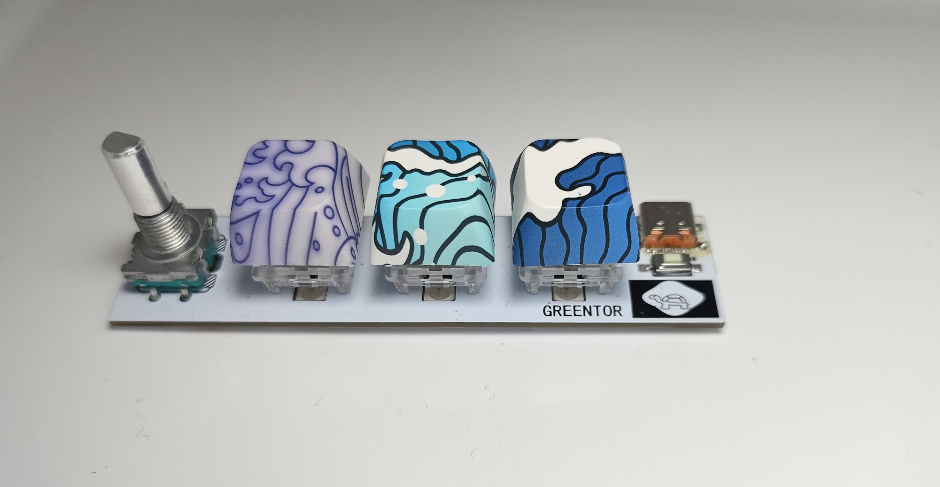
Touchless infinite dimming dragon year mascot
A color silkscreen printing plate for a regular octagonal touch-sensitive stepless dimming dragon-themed circuit design; Who says we don't have a Chinese dragon?

The "Warm Winter Creation" activity requirements:
When I first saw this activity, my immediate reaction wasn't to see the requirements, but to the coupons on the cover. Four types of free coupons (not really), it was practically a no-brainer to participate. After registering, I looked at the requirements—a warm and festive Chinese New Year/Christmas theme.
My first thought upon registering was definitely the nearest holiday—Christmas. I initially thought of a Christmas tree, but couldn't figure out how to make it three-dimensional. Some of my previous single-sided designs looked too flimsy, and since I'd already made them, I couldn't copy them, so I put them aside for a while. Because I often get free materials, but the quantity is very limited—only one or two, basically enough for two samples—I've always had the idea of using all five boards simultaneously, but I haven't had a clue how. Sure enough, one day when I opened the registration form and filled out the link, I saw He Diangong's idea. Sure enough, there was a Christmas tree! He used five free boards to create a three-dimensional Christmas tree—a fantastic idea. Here's his project link—a mini Christmas tree based on the WS2812.
The special nature of being able to get free materials also led me to be too frugal, foreshadowing the poor lighting effects in the final product. Of course, the main point here is that the Christmas theme didn't work for me. So, for me, the remaining four words basically fall into the category of New Year, which is related to red. Then, based on the fact that the maximum freebie size of the board is 100*100, I thought of a square "福" (Fu, meaning good fortune) character, since it can be rotated into a rhombus shape, and the through hole for GND can be used to hang a rope, which is simply ingenious! However, I then looked at the rules and found that it does not allow simple lighting (at that time, I hadn't even figured out how to light it). To hang the "福" character, it doesn't need to be connected to batteries, so it must be battery-powered, and there should be charging and discharging interfaces, and I need to consider adding a microcontroller to avoid it being just simple lighting. Due to my limited skills, I shelved it.
Inspiration came
when I was at a loss for the design of the four types of coupons, the Year of the Dragon mascot Long Chenchen became popular (lol), sparking a lot of discussion. Even my favorite five-star general, General MacArthur, commented on it - a large-scale documentary "The Year of the Dragon Mascot". I was thinking about whether there were any elements related to the Year of the Dragon, and then I came across the "[Hupu Sharp Review] Annual Outstanding Year of the Dragon Mascot Selection", and the first place was "Dragon Hero"! I spotted a familiar figure—Shendu. I'd just rewatched Jackie Chan Adventures with a premium membership, and the inspiration for the design came from the abstract concept of the talisman or Shendu's disc shape. Initially, I considered using a Shendu statue
for the pattern and shape
, but the size wasn't large enough to represent the talisman slot. Then, I happened to be watching episode 11, Shendu's resurrection, and saw the distinctive Shendu symbol. I decided to use this as the color screen printing pattern, and the shape also used the talisman's form from the anime. I
embarrassingly miscalculated the octagonal parameters when I started designing. Looking at the talisman, I thought a regular octagon should be obtained by subtracting the same length from both sides of the existing square. However, no matter how I subtracted, I couldn't get a regular octagon. After subtracting, it felt strange. I happened to have seen a project with an octagon before, and after looking at it, I realized how absurd my calculation was. So, I directly copied the shape, and also copied the Tai Chi symbol. Thus, the pattern and shape of the entire board were temporarily resolved. For the
outer shell and panel,
I chose LEDs for the top and bottom shells respectively. Although the 6060 and 9000R models weren't marked as transparent on the parameter panel, the small LEDs actually allowed light to pass through the casing. Considering the light-blocking effect, a black material like PLA
was chosen, and a frosted thin-film panel was opted for. The intention was to avoid using any screws that would compromise the overall shape (although the bottom casing was eventually damaged). In fact, the frosted finish has minimal effect on preventing light transmission. Strong light blocking was prioritized.
Based on the PCB shape, a simple casing model was generated using LCSC EDA, but it was very basic, with many things difficult to adjust. This forced the use of other modeling software. It's worth mentioning that LCSC EDA's board frame layer cannot be parametrically modeled; everything had to be done manually. Some shapes were extremely difficult to design. Then, only Fusion 360 VIP could export to DXF format, rendering the design useless. So, I had to redraw it in CATIA and export it again, then use Fusion 360 to further refine the internal structure of the casing.
Since this was the first time trying both the panel and the casing, there were many mistakes in the printing materials and various selection tests, resulting in an unsatisfactory final product. However, the initial intention of the event was probably to encourage everyone to try out new functions
and modify
the circuit design. I considered dual op-amp breathing lights, flowing lights, etc., but I wanted the lighting effect to gradually brighten, emitting red light in the eyes area, which matched the original animation. Therefore, I chose touch stepless dimming. I originally planned to use a microcontroller, but due to time constraints, I ended up using a pure hardware circuit. At this point, I made an old mistake again: I used a basic LED light that I already had on hand, which is a big no-no for a work that requires lighting effects. Fortunately, I also chose a full red light, otherwise it would have been completely unwatchable.
The original bottom layer of the pattern was a Tai Chi diagram, which, combined with the two touch springs, perfectly preserved the aesthetics of the pattern itself. However, since I had never tried color screen printing before, I was unsure if the circuitry would be exposed, and the integrity of the components on the back had already been compromised. So, I simply used the Jackie Chan Adventures icon, which matches the original animation. I added an LED on the back as an indicator light, and placed the protruding part of the touch spring in the dark part of the top layer pattern to maximize the integrity of the top layer pattern.
There are several design options for the housing and panel, but due to time constraints and unfamiliarity with these new functions and processes, the safest option was chosen: placing it internally, with the panel providing light shielding and the housing having slots for light transmission. Various tolerances and the fit between the upper and lower housings were also considered (a long section was cut off by a bug), so I'll leave it at that. The schematic design is
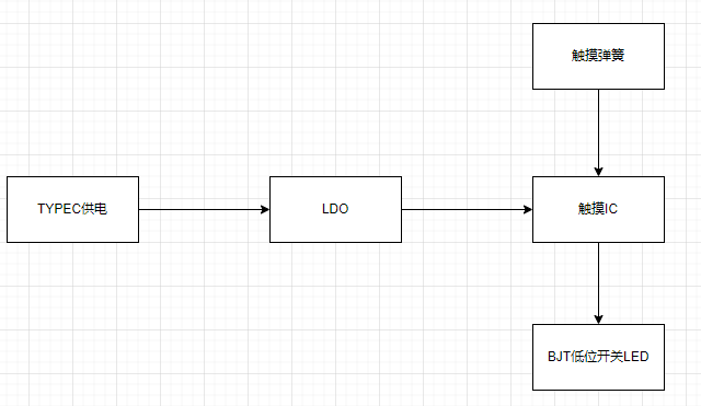
a very simple touch chip design, almost an example. The actual design is below, and the layout references a touch-sensitive stepless dimming snowflake LED. I came across this project when I found the schematic too ugly after completing my design. Fan-out netting is a great feature; the experts really know how to do it.
The PCB design
layout
idea was to place all components except the lighting on the bottom layer to ensure a neat and complete look with the colored silkscreen on the top layer. However, due to habit, the TYPE-C port was placed on top, and I didn't realize that the connector isn't long and wouldn't protrude from the top layer when reversed. If the solder amount is controlled well, the top layer can be very flat. Although it doesn't look out of place, I strongly recommend placing the TYPE-C port on the bottom layer as well.
The lack of any testability design on this board is a major mistake. The original idea was that there were no technical or soldering difficulties (where did they get the nerve?). The TYPE-C interface, in particular, was a 6-pin power-only version, and the fact that it wasn't placed on the back was also a flaw. This made testing the TYPE-C extremely difficult due to poor soldering. Multimeter probes had to be inserted on both sides simultaneously, and there were no through-holes. Those replicating this board must learn from this lesson and make the necessary changes (is this even worth replicating? XD). When routing the traces,
pay
close attention to ensuring that the input and output signal lines of the critical touch chip are not interfered with by other traces. Consider copper shielding, and keep input signal lines as short and thin as possible, around 5mil is recommended. You can refer to JLCPCB's PCB design specifications for more information. The
software specifications
require no software code; it only needs power to operate. The physical
product demonstration explains that
the TYPE-C socket on the casing was initially enlarged to include the plastic parts, considering potential variations in insertion and removal lengths. However, actual testing revealed that this enlargement was unnecessary. Users can refer to their casing wall thickness to determine if a larger opening is needed at the socket. The TYPE-C engineering drawings do not specify insertion depth, so you can refer to my TYPE-C cable; it should just exceed the wall thickness after insertion.

Note:
Capacitor values are recommended between 1nF and 10uF, with a default of 47nF. During the functional testing phase, the capacitor value's impact on sensitivity is not significant; it lights up even with a manual press. Adjustments can be made gradually after using the mold.
Soldering TYPE-C is very important!!! When using a soldering iron, solder the terminals first, then the socket. When using a hot air gun, pay attention to the temperature to avoid melting the solder core. Use plenty of flux.
Other attachments are uploaded.


PCB front view.jpg
PCB back side.jpg
Actual product assembly image.jpg
Front lighting effect.mp4
Reverse lighting effect.mp4
Overall lighting effects.mp4
PDF_Touch-enabled infinitely dimming Dragon Year Mascot.zip
Altium Touchscreen Infinite Dimming Dragon Year Mascot.zip
PADS_Touch Infinite Dimming Dragon Year Mascot.zip
BOM_Touch-enabled infinitely dimming Dragon Year Mascot.xlsx
96097
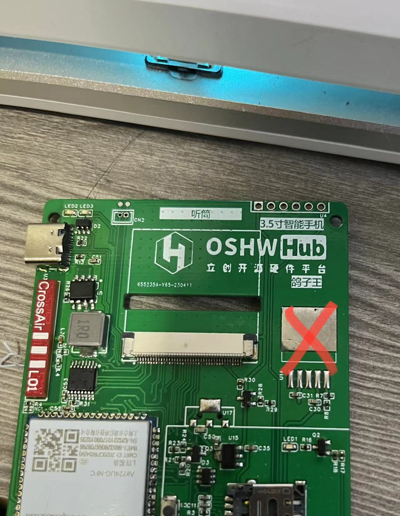
Call for Submissions | 3.5-inch Smartphones
A phone that goes back to basics, a phone whose functions are entirely customized by engineers. That's it!
In our lives, smartphones
occupy most of our time. If you want to create a phone that goes back to basics, one that can only send text messages and make calls, and that you can use cash when you go out, you can start a more relaxed lifestyle, give up the habit of constantly checking your phone, and do more meaningful things.
Simple description of mobile phone functions:
The main interface is built using LVGL, which facilitates later function expansion and maintenance.
It can make and receive calls
and send and receive text messages.
Progress record:
PCB design is completed, and the connection is verified using the core board and adapter board. Awaiting PCB prototyping.
PCB prototyping has been completed, and the delivery date is shown as 4/13. PCB is awaiting receipt. Component procurement
has begun . Component procurement is
complete and awaiting receipt.
Components have arrived and have been signed for.
PCB has arrived, and hand soldering of components
is complete . Firmware is complete.
UI design and
4G communication debugging are complete.
All projects are completed and released. The project
continues to check for missing components and supplement procurement.
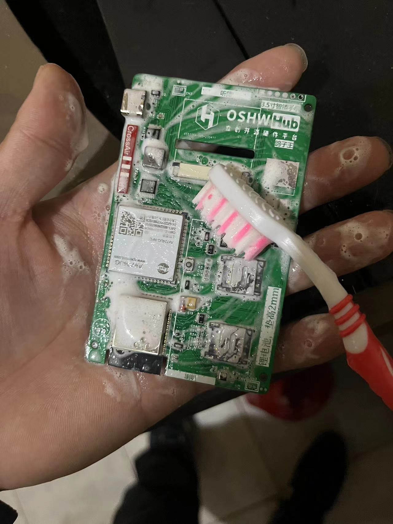
After hand soldering, the PCB is cleaned. Actually, I think using hand soap is better than board cleaning water. After washing and drying, the PCB smells nice.


Awaiting the arrival of supplementary procured components. The main open source project used in the project
is ESP-IDF v4.4.4 - Espressif IDF development framework. This project uses this framework to create the system firmware, version release v4.4.
esp_lcd_ili9488 - display driver, I8080 parallel port 8-bit, you can refer to this example (I worked with a foreign expert)
. lvgl - The GUI interface library version must be 8.3.6. The following are
precautions
: To ensure you can expand functionality and use it normally, please read
the firmware source code carefully. When reading the firmware source code, please ensure you are:
familiar with FreeRTOS, especially the threads and queues in RTOS
; proficient in C language development;
familiar with and understand LVGL
; use
the CC BY-NC protocol for RAM. The software and hardware are open source, but only for learning purposes; commercial use is prohibited.
Subsequent additions to
the device should allow normal use of WIFI and 4G internet connection, and also have basic mobile phone functions such as making and receiving calls and sending and receiving text messages. However, in real-life scenarios, mobile payment has become an indispensable part. In addition to implementing basic mobile phone functions, mobile payment also needs to be added. However, the problem is that mainstream mobile payment services such as Alipay and WeChat Pay cannot be used on this device. If the core is changed to RK3588 and the Android system is used, the problem can be solved, but this deviates from the original intention of the project. The mobile payment problem is currently unsolvable.
There's no outer shell available, and I really don't want to model it anymore. Could someone skilled at modeling and making a suitable shell?
Currently, it's a double-layer board with interconnected layers, and impedance is an issue. Later, we could switch to a four-layer board for impedance
matching. Replicating the project would require some expertise. For UI development, NXP's GUI-Guider is much more efficient than Squareline Studio (in my opinion).
We could use reserved memory to implement app installation injection, but I'm not considering those for now. This is just an idea;
I'll work on the system firmware later.
Mobile phone verification video~1.mp4
PDF_Call for Submissions_3.5-inch Smartphone.zip
Altium_Recruitment Notice_3.5-inch Smartphone.zip
PADS_Call for 3.5-inch Smartphones.zip
BOM_Call for Submissions_3.5-inch Smartphone.xlsx
96098
send35510dan NT35510 4.0-inch LCD screen back panel
The back panel features a 4.0-inch 480x800 LCD screen. The screen IC is NT35510, and the ribbon cable connector is FH26W-45S-0.3SHW 45PIN. An ESP8266 and a WB3S (H238) are also shown on the back.
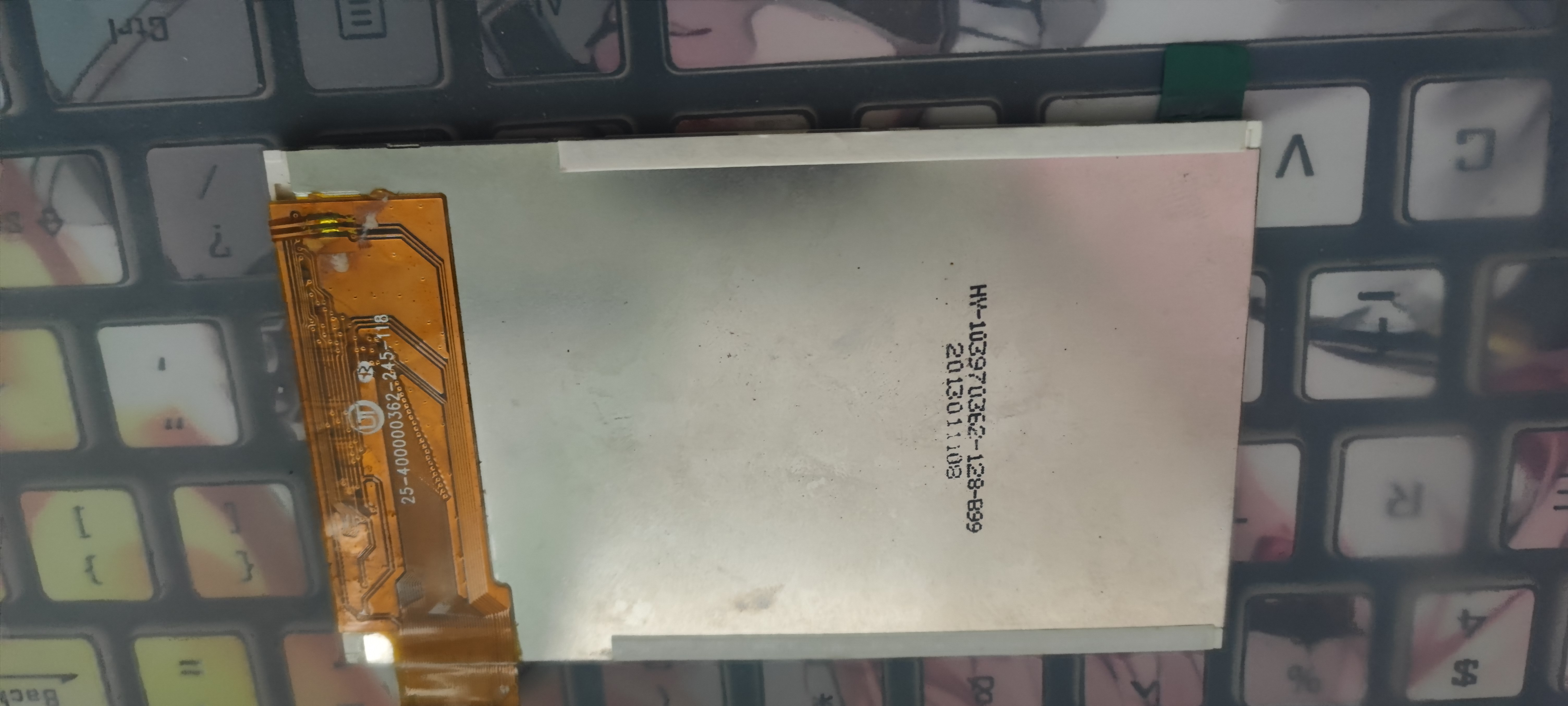

The screen
was obtained from Xianyu (a second-hand marketplace). It's a 4.0-inch, 480x800 resolution screen with an NT35510 main controller, using an 8080 parallel port 16-bit. I couldn't find detailed information...
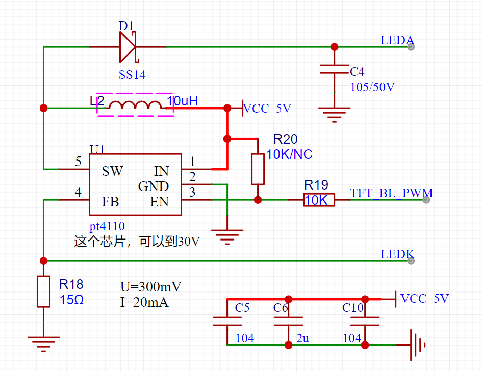
the backlight boost
converter is a PT4110. The TFT_BL_PWM here isn't actually connected, meaning the backlight control isn't brought out from the socket. Therefore, R20 is a 10k resistor.
For the modules,
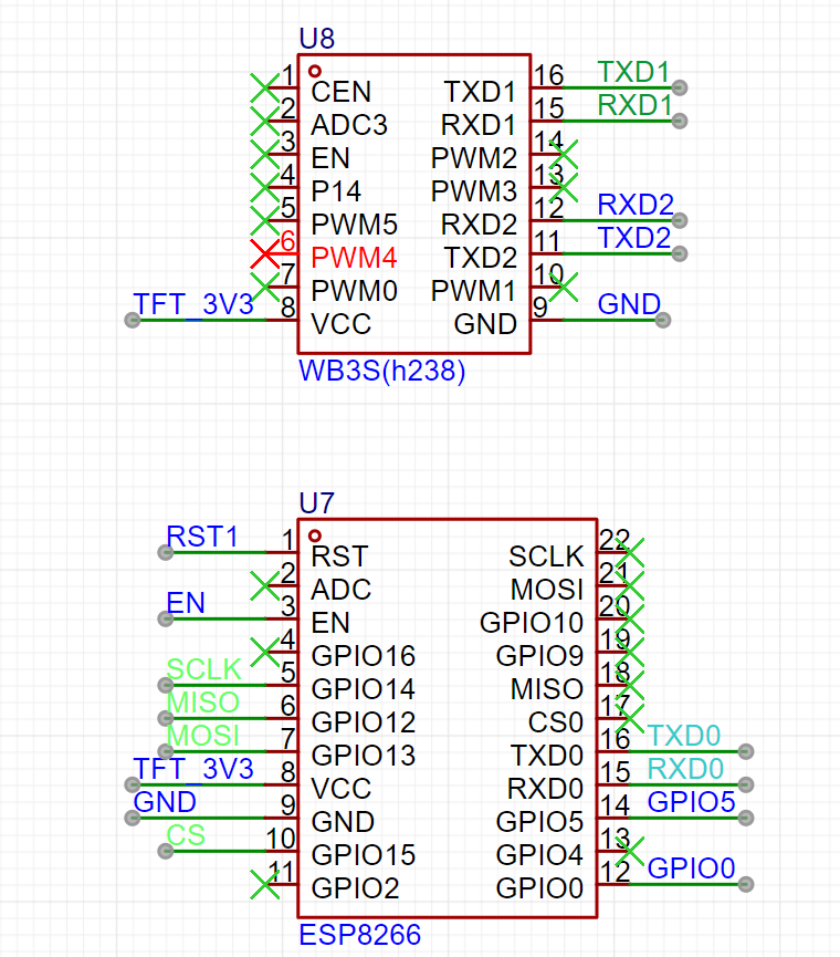
there's an ESP8266 and a WB3S (a custom module). I included them because the backplate is there, and leaving it empty felt wasteful.
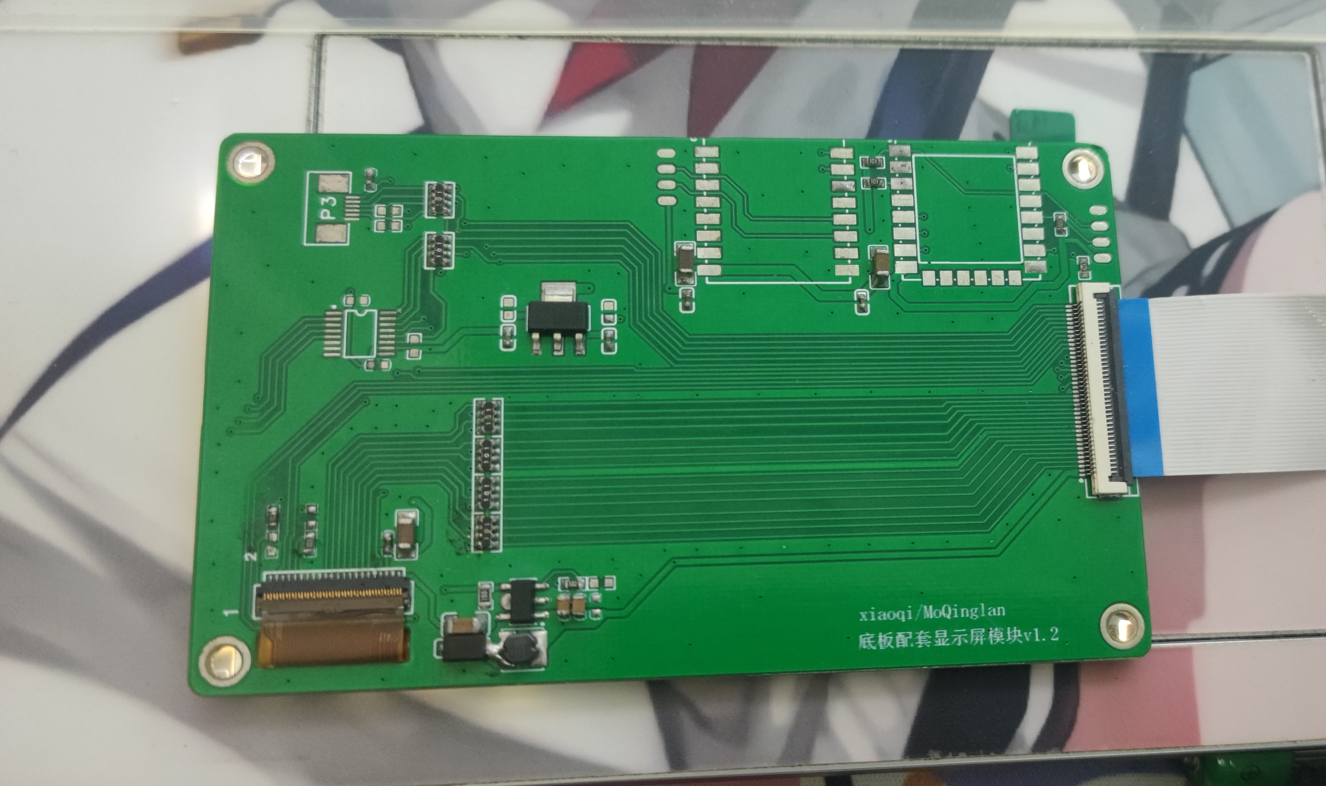
I also made an adapter board to connect to the Zhengdian Atom socket.
This PCB is 60x100mm, using a 40P FPC. If you want to use it with the Zhengdian Atom F1 core board, you can modify the FPC yourself.
The drawing might not be very good, please excuse the poor quality.
That's all.
NT35510.zip
PDF_send35510dan NT35510 4.0-inch LCD screen back panel.zip
Altium_send35510dan NT35510 4.0-inch LCD screen back panel.zip
PADS_send35510dan NT35510 4.0-inch LCD screen back panel.zip
BOM_send35510dan NT35510 4.0-inch LCD screen back panel.xlsx
96102
USB isolated protection HUB
USB hub, using USB2514 and ADUM4160 chips.
Be careful to avoid purchasing counterfeit USB2514Bi chips. The image shown is from the first version and was incorrect; the error has been corrected in the project.
PDF_USB Isolation Protective HUB.zip
Altium_USB Isolation Protection HUB.zip
PADS_USB Isolation Protection HUB.zip
BOM_USB Isolated Protected HUB.xlsx
96103
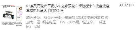
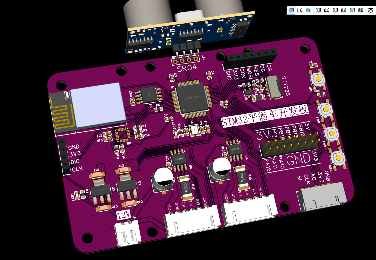
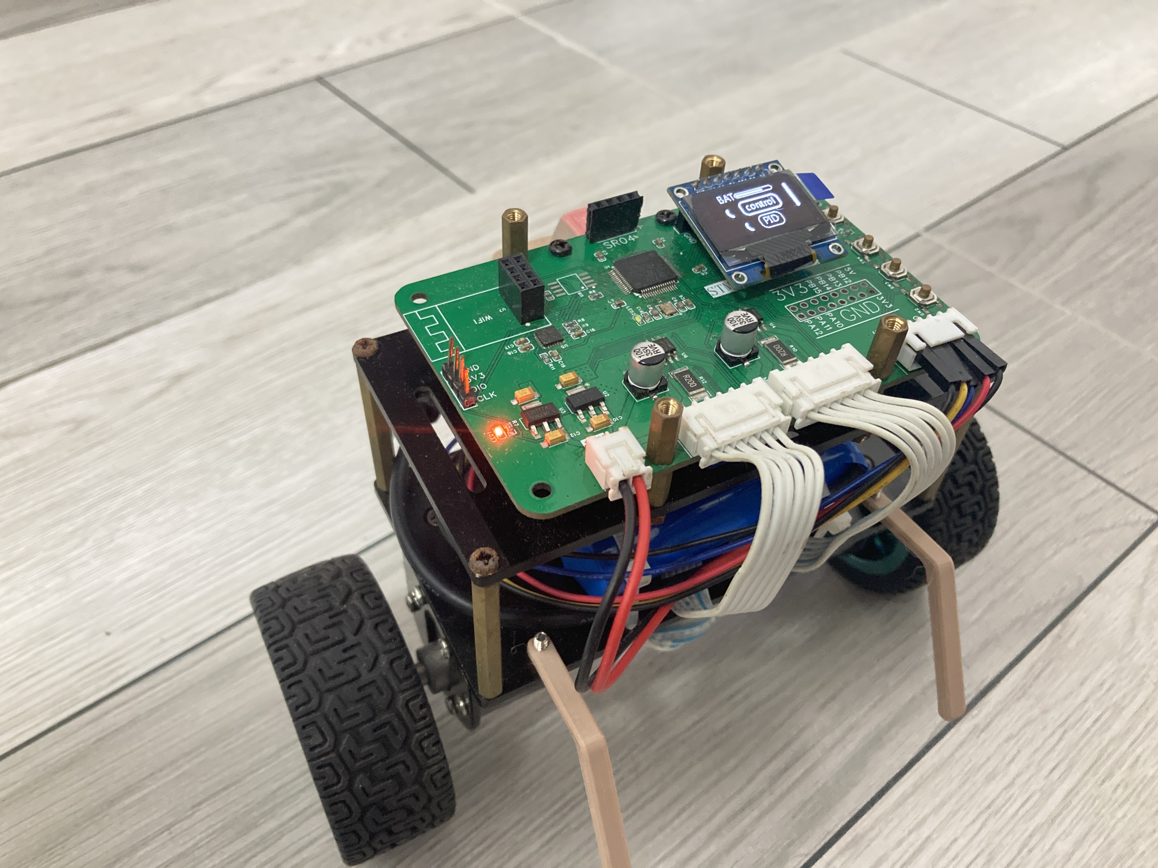
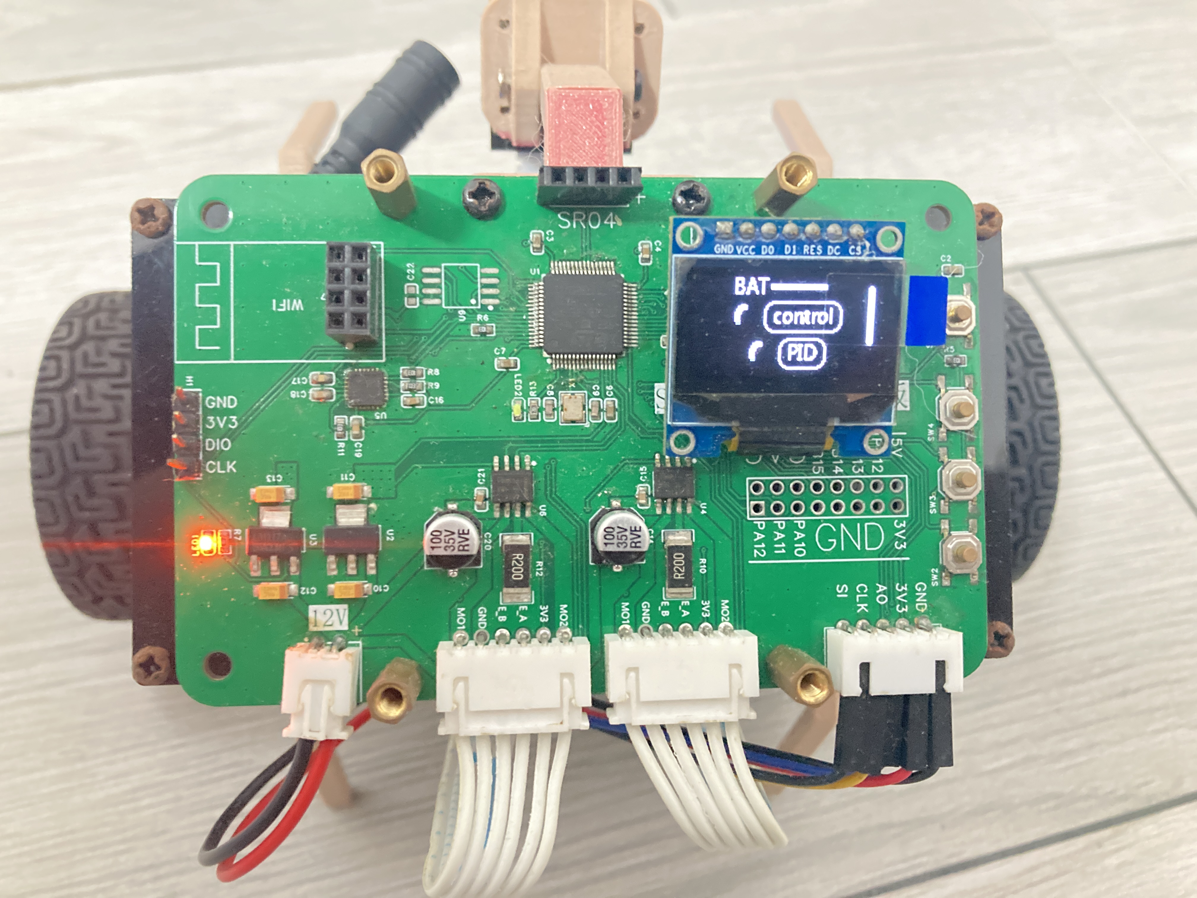
Balanced Vehicle_F103RE
Self-balancing scooter project based on STM32F103RE
The hardware portion of the self-balancing scooter project
uses an STM32F103RE as the main control
board. Interfaces include: screen, Wi-Fi, buttons, encoder interface, motor interface, expansion interface, TSL1401 interface, and ultrasonic sensor interface.
Most functions have been verified. The
drawbacks are the lack of a serial port interface, a power switch,
and a battery ADC.
Using a poor-quality LDO might burn out the chip
. An ST7735 interface is unnecessary due to insufficient chip memory.
For downloads, please use STLink.
Software: https://github.com/1696774082/Balance_Vehicle_F103RE
GitHub. The chassis was purchased from Taobao.

a882ece6ab16ef847bc038bf00ed43fd.mp4
1ab39c94ce8cf82b70aabfbe0941dac6.mp4
PDF_Balanced Vehicle_F103RE.zip
Altium_Balanced Vehicle_F103RE.zip
PADS_Balanced Vehicle_F103RE.zip
96106
electronic


 京公网安备 11010802033920号

 1200SGG6002F2KB


