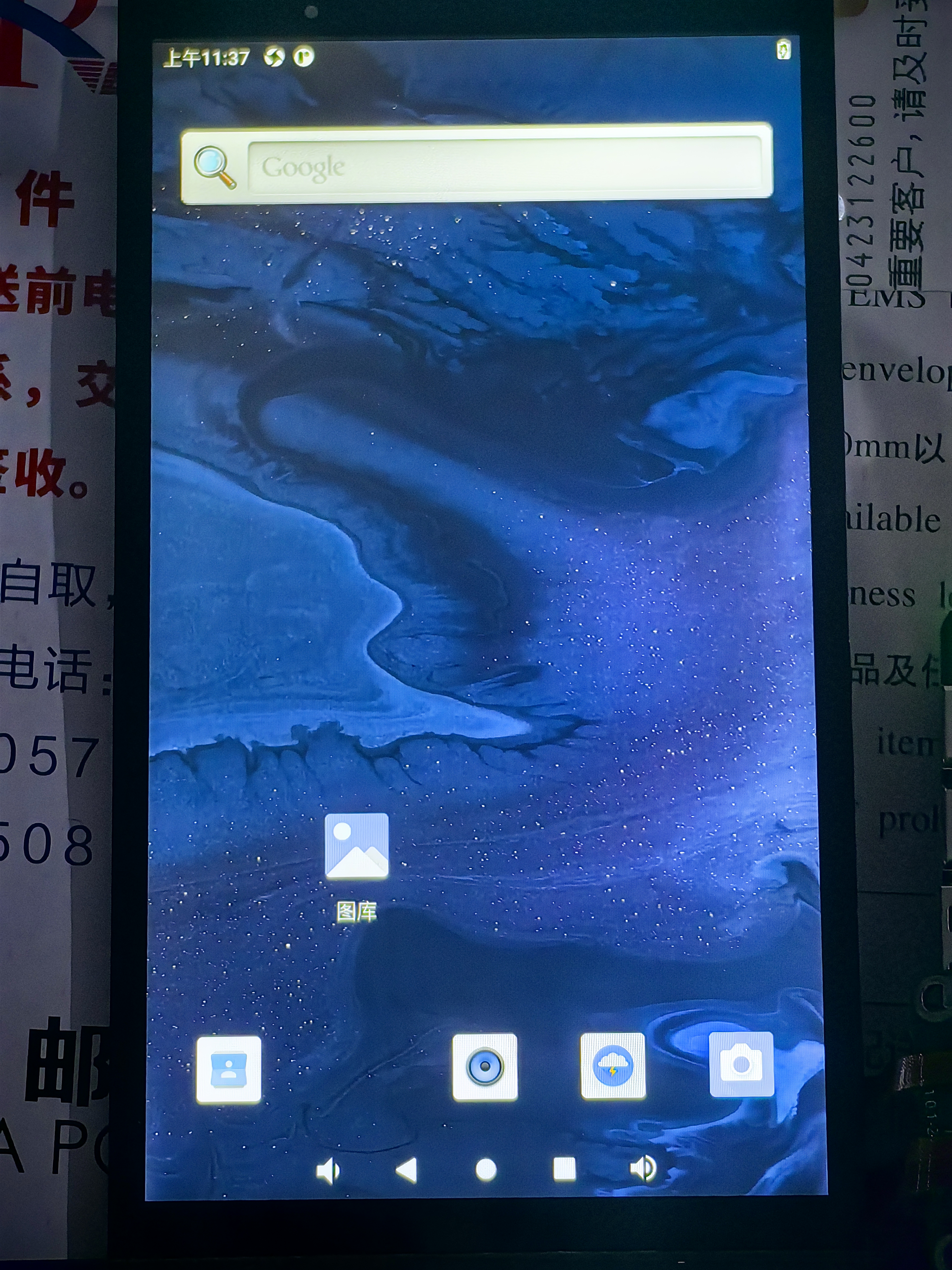
Based on leefei's work, level conversion and impedance matching were added...
Although 3.3V works, the 2.8V and 1.8V specifications in the screen manufacturer's documentation are not satisfactory...
It's a four-layer board; if you don't like it, you can modify it to a two-layer board yourself.
The color correction in the JLC04161H-7628 free impedance structure datasheet from JLCIC is BGR (15 00 02 CC 09), and 08 is RGB.
Touch can be driven using the original SDK with its built-in GT9XX, but a different configuration file is needed (provided in the datasheet).
The screen was bought on Xianyu for 39 RMB with free shipping: https://m.tb.cn/h.5K5M0I0?tk=U8FPWhyMmdm.
When buying the screen, I messaged the seller, mentioning that Sakura recommended it, and they included a screen BT socket.
Data download:
https://gitee.com/fengmoxi/tspi-stl6_0_1_2_a
. Screenshots:
TSPI-STL6.0-1-2-A.mp4
PDF_Taishanpai 6-inch Screen Adapter Board [Luxury Version].zip
Altium_Taishanpai 6-inch Screen Adapter Board [Luxury Version].zip
PADS_Taishanpai 6-inch Screen Adapter Board [Luxury Edition].zip
BOM_Taishanpai 6-inch Screen Adapter Board [Luxury Version].xlsx
96312
HR7P169BFGTF PWM dimming development version_2024-01-20_10-23-30
Originally, I planned to use what I had on hand to make a board for aquarium lights with timer and dimming functions. But as I was drawing, I decided to bring out all the chip pins and use it as a development board. It doesn't matter if the board for aquarium lights is a bit bigger.
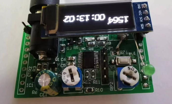
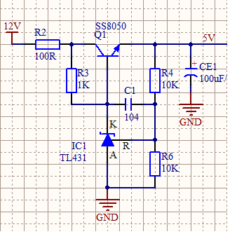
First, regarding the power supply, the adapter for the aquarium light I bought previously was a 21V output, so a step-down circuit was needed. I made a simple step-down circuit using a TL431 and SS8050, which should work with most common 5-25V adapters used in homes.
Secondly, as a PWM dimming board, the PWM control circuit is essential

. I added two potentiometers, a tactile switch, and two LEDs for control and interaction. Each pin of the chip is also connected to a header for connecting external modules, such as the OLED module shown in the initial screenshot.
Note: 1. The two GND pins at the DC input connector on the PCB need to be connected with jumpers. Some of my DC005 chips have these two pins connected to GND, while others do not.
2. Attached is a simple PWM timed dimming program source code.
pwm_light.zip
PDF_HR7P169BFGTF PWM dimming development version_10-23-30.zip
Altium_HR7P169BFGTF PWM dimming development version_10-23-30.zip
PADS_HR7P169BFGTF PWM dimming development version_10-23-30.zip
96314
MP3
This is a practical training project I did in the first semester of my junior year: an MP3 player based on the STM32F103C8T6.
1. In terms of resource allocation, serial port 1 connects to the MP3 module, and serial port 2 connects to the Taojingchi serial screen.
2. All controls rely on the touchscreen (except for the power switch and jumper function selection).
3. It can play music, pause music, skip to the next song, change the music style, change the volume, add songs (with power-off protection), update the MP3 module on the SD card (no card reader needed, directly recognized by the Android interface), and update the serial screen information (directly via the Android interface).
4. The Android interface allows direct charging.
5. It also has a speaker interface and a headphone interface.
6. Keil files and Taojingchi serial screen files: Link: https://pan.baidu.com/s/1R3zv4ZSunctqXcQYfwpEsA?pwd=8wdh Extraction code: 8wdh
7. Bilibili video link: 【Practical Training Project - Bilibili】 https://b23.tv/UKQOgNN
PDF_MP3 player.zip
Altium_MP3 player.zip
PADS_MP3 player.zip
BOM_MP3 Player.xlsx
96315
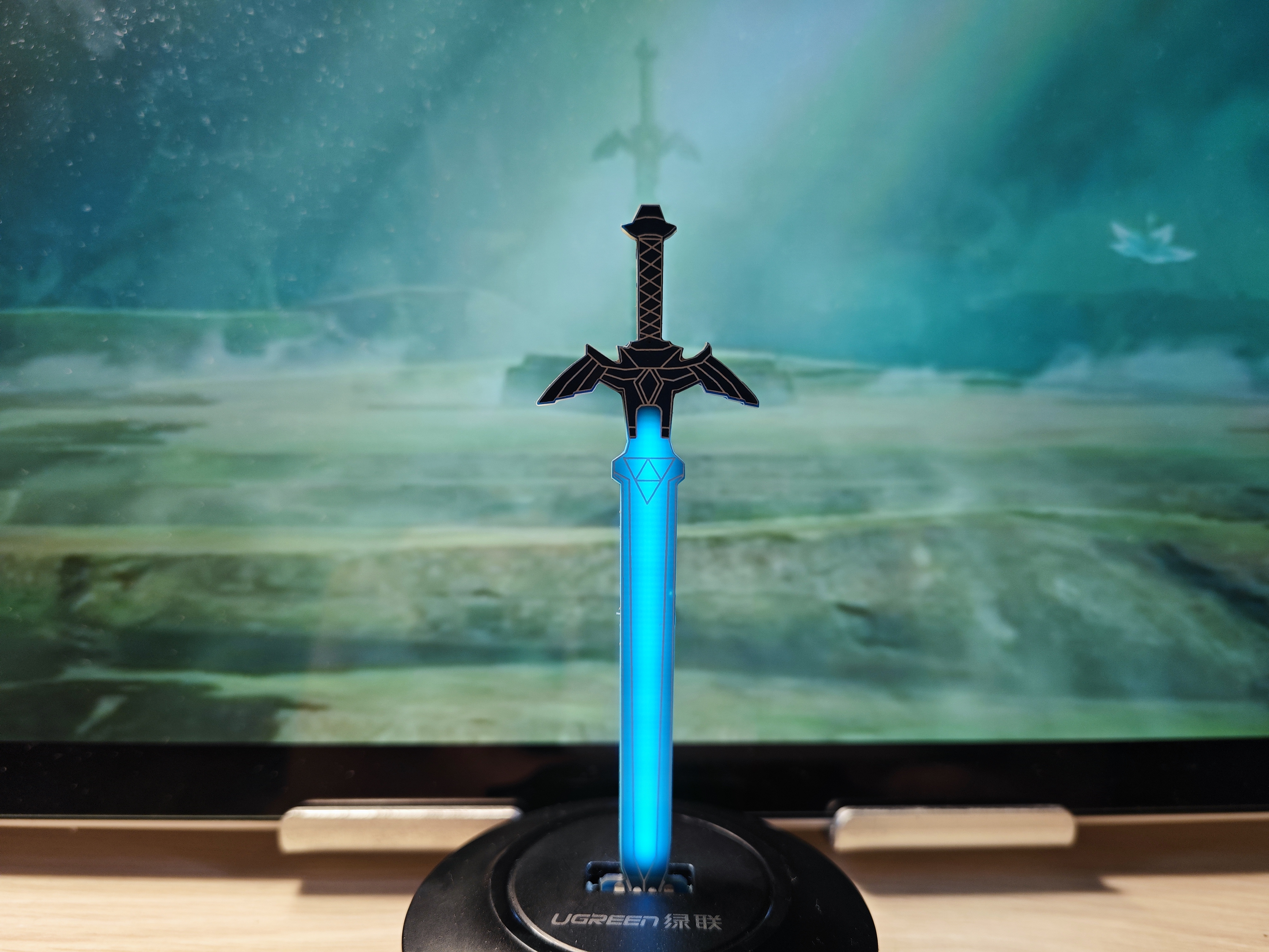
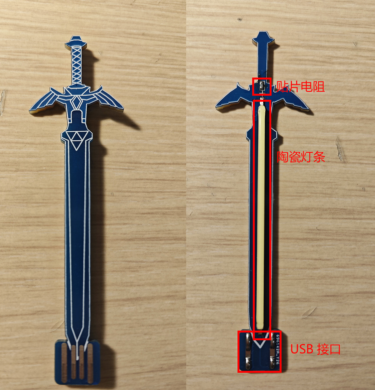
Minimalist Master Sword [USB-A]
With its minimalist design, requiring only a resistor and an LED, you can have a cool master sword.
This project originates from (under editing) the NE555 Breathing Light - Master's Sword - JLCPCB EDA Open Source Hardware Platform (oshwhub.com).
The base has been removed, and the blade has been modified to use a USB-A interface, allowing direct connection to a computer or hub.
The minimalist version requires only a 50-ohm surface-mount resistor and a 68mm ceramic LED strip, providing constant illumination, and the PCB components unrelated to the blade can be perfectly hidden.
Borrowing from the USB plug LED - JLCPCB EDA Open Source Hardware Platform (oshwhub.com), the PCB is directly used as the USB-A port, eliminating the need for soldering male connectors; simply add solder to the back pads to increase thickness.
There is also a breathing version using a 555 timer, also with a USB-A interface.
PDF_Minimalist Master Sword Version [USB-A].zip
Altium - Minimalist Master Sword [USB-A].zip
PADS - Minimalist Master Sword [USB-A].zip
BOM_Minimalist Master Sword Version [USB-A].xlsx
96316
NAM12S06-D module power supply 50*50
NAM12S06-D Power Module
The NAM12S06-D power module experimental board adds 3.3V and 5V switching.
8c677c16c1ab9b6283ed6e04a80964cc.mp4
PDF_NAM12S06-D Module Power Supply 50_50.zip
BOM_NAM12S06-D Module Power Supply 50_50.xlsx
96317
STC89C52RC_LQFP
Based on the STC89C52RC core development board, basic hardware and software development has been completed.
Hardware Features:
1. 4 independent LEDs
; 2. 4 independent buttons, 1 reset button;
3. Outgoing P0, P1, and P2 I/O ports;
4. Onboard AT24C08 oscillator with 1MB EEPROM external storage;
5. Serial communication (for baud rates above 2400, the 12MHz crystal oscillator needs to be replaced with an 11.592MHz oscillator);
6. Type-C interface, using the official STC software STC-ISP for cold-boot-free one-click download.
Software Completed:
BSP driver software and hardware projects for LED, KEY, EEPROM, UART, and other peripherals have been completed.
Address:
https://gitee.com/Mokun_gitee/stc89-c52-rc_-core-board.git
PDF_STC89C52RC_LQFP.zip
Altium_STC89C52RC_LQFP.zip
PADS_STC89C52RC_LQFP.zip
BOM_STC89C52RC_LQFP.xlsx
96318
electronic


 京公网安备 11010802033920号

 752083472GP


