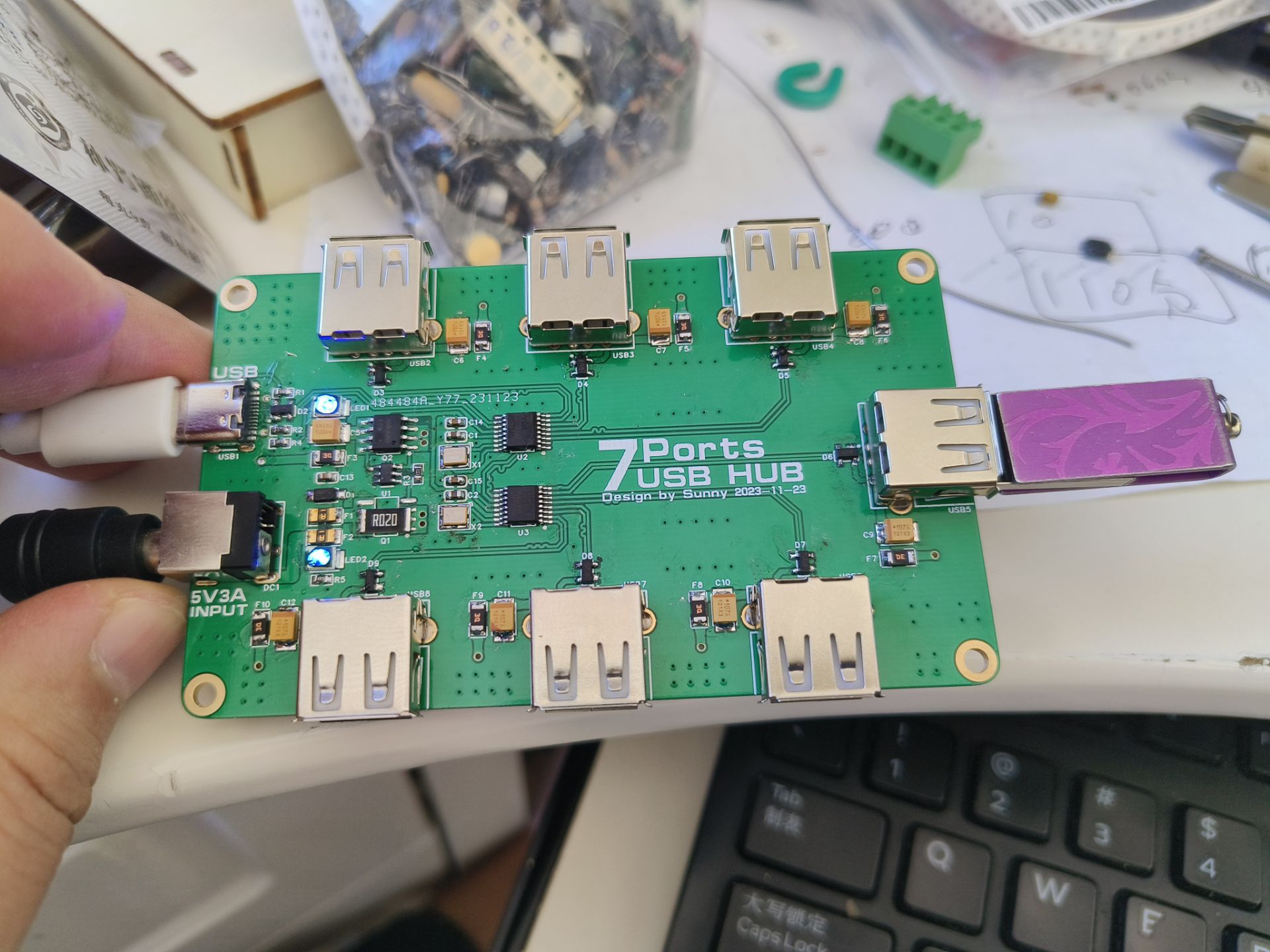
This project, designed using LCSC EDA Professional Edition, is a 7-channel USB hub based on the Chinheng CH334R chip.
1. The design uses two CH334R chips cascaded to expand to seven USB 2.0 ports. Since the CH334R is an MTT mode hub, cascading has minimal impact on bandwidth, offering a better experience compared to STT mode hubs. The CH334R has fewer external components, only a 12MHz crystal and capacitors, making the design relatively simple. All USB buses in this design are differentially lengthened. While this doesn't have a substantial effect, I firmly believe that good design practices will eventually yield unexpected surprises.
2. The design uses a Linear Technology LT4412ES6 for USB VBUS power path control. In the circuit, the LT4412 and PMOS are equivalent to an ideal diode connected in series with the VBUS power supply. When the external adapter power is not connected to the circuit, or when the adapter output voltage is lower than VBUS, the LT4412 controls the PMOS to conduct, and the main USB's VBUS will provide power to the hub chip and all extended USB ports through the PMOS. When an external adapter is connected and its output voltage exceeds the VBUS voltage of the main USB port, the LT4412 controls the PMOS to turn off, preventing backflow of power from the power adapter into the main USB port. At this time
, the adapter will provide power to the HUB chip and all extended USB ports. The main USB port uses a 16-pin Type-C interface, while the extended USB ports use Type-A interfaces. All USB ports are equipped with ESD protection and VBUS self-resetting PPTC, providing some resistance to electrostatic discharge and short circuits. No load protection switch is included because the CH334R does not support it; users interested in this feature can upgrade to a controller version that supports load switch management to add and modify it themselves.
PDF_CH334R-based 7-channel USB-HUB.zip
Altium_CH334R-based 7-channel USB-HUB.zip
PADS_CH334R-based 7-channel USB-HUB.zip
BOM_CH334R-based 7-channel USB-HUB.xlsx
96920
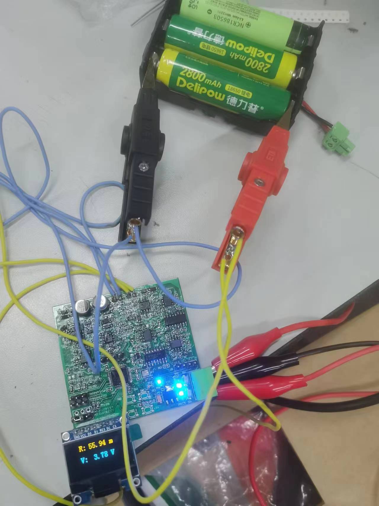
Battery internal resistance tester
Homemade Battery AC Resistance Measuring Device
AC battery internal resistance measuring device, test frequency 1kHz, accuracy 1 milliohm (5% accuracy). Measurement range below 2k ohms. Employs switch phase detection and programmable amplification to extend the measurement range.
#### Code link:
https://gitee.com/aaffzx/battery
PDF_Battery Internal Resistance Tester.zip
Altium_Battery Internal Resistance Tester.zip
PADS_Battery Internal Resistance Tester.zip
BOM_Battery Internal Resistance Tester.xlsx
96921
Transient response testing tools
Replicate Liqi's load transient testing tool
This design replicates a Liqi load transient testing tool: Function

Introduction:
This design generates very fast load steps by rapidly switching resistors on and off using an MCU-driven MOS transistor. It can be used to quickly verify the pulse load behavior of a voltage regulator and to check the stability, layout resonance, and input power ringing of a DC/DC converter. Various pulse load resistors can be selected via jumpers, and the static load level can be set using an adjustable power resistor. The pulse load frequency and duty cycle can be adjusted via buttons. By measuring the regulator output voltage during a fast load step, the behavior of the regulator control loop can be observed.
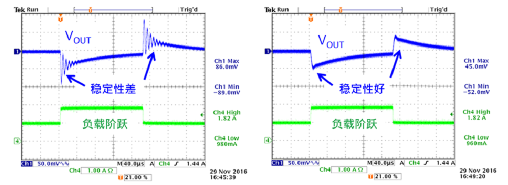
In simpler terms: The MCU generates a PWM signal with an adjustable duty cycle and frequency, which drives an N-MOS transistor via an inverter as the gate driver to generate a pulse load. The load size can be switched by controlling the resistor connected to the circuit using jumpers.
A single 18650 battery is used for power supply, isolated from the power supply under test for ease of use. An onboard LED indicator displays the battery level; it needs to be removed for charging when the battery is low.
Instructions for Use:
The self-locking switch PWR controls the power supply of the entire circuit.
The D+ and D- buttons control the duty cycle, increasing or decreasing by 5% with each press, up to a maximum of 50%. Note that the power on each resistor should not exceed 1W.
The Freq button controls the PWM frequency, switching between four preset frequencies.
The red LED indicates the battery status: off at 4.2-4V, flashing slowly at 3.8-4V, flashing quickly at 3.6-3.8V, and constantly lit below 3.6V, requiring charging.
The blue LED is a constant power indicator.
For detailed power supply testing instructions, please refer to Liqi's explanation in the link above; it is very detailed and will not be repeated here.
The attachment contains the compiled program and source project.
TransientResponseTestTool_hbozyq.hex
TransientResponseTestTool_hbozyq.7z
PDF_Transient Response Testing Tool.zip
Altium_Transient Response Testing Tool.zip
PADS_Transient Response Testing Tool.zip
BOM_Transient Response Testing Tool.xlsx
96922
electronic


 京公网安备 11010802033920号

 SPMCK16Z1MFC16


