
 Secondly, the width of my multi-function pen is also wider than that of the original project because I think that being faster would make it easier to draw on the board and also increase the rigidity of the board.
 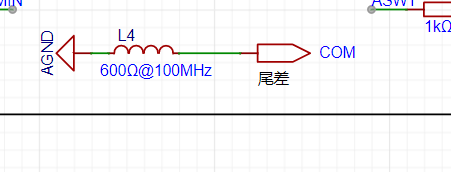 After modifying this as shown in the diagram,
 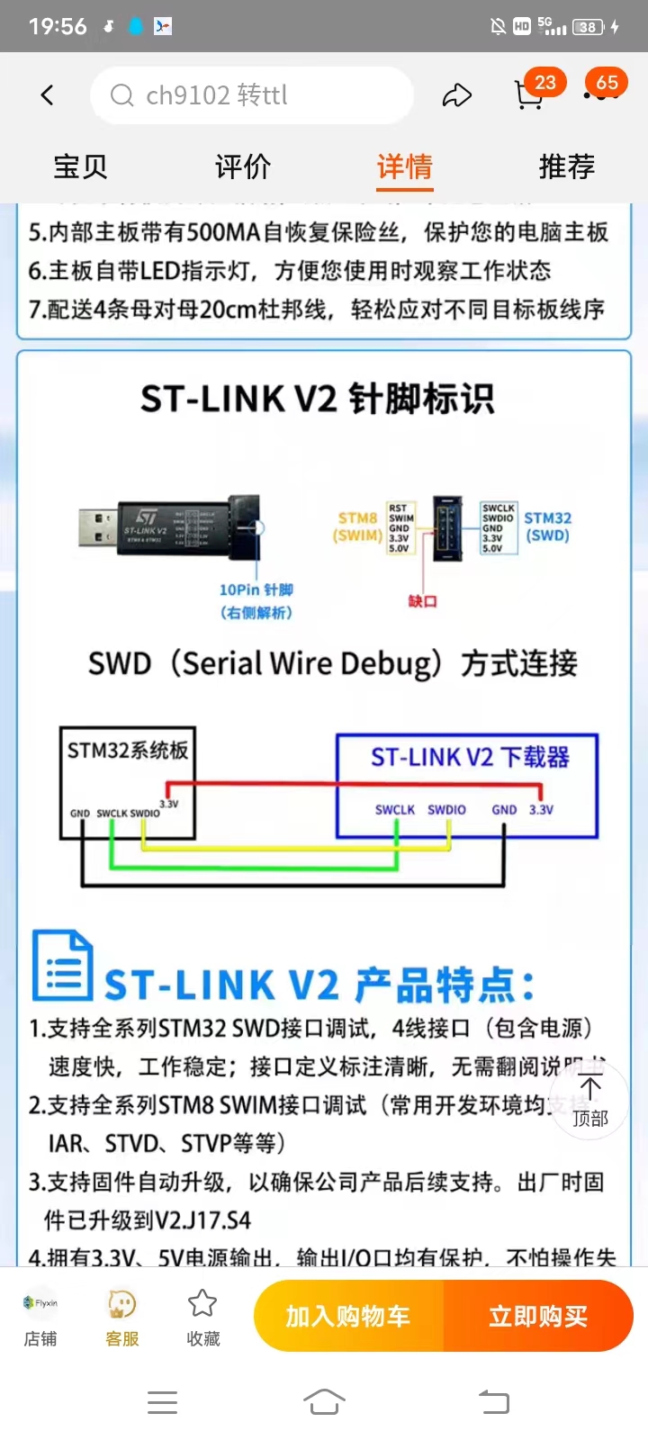 This is the ST-Link wiring diagram. Pay attention! Do not cross-connect the wires. (Secondly, J-Link cannot download CW32; it seems to be unrecognized. I've tried it myself,
  and it doesn't work.) This is the error. If this error occurs, it means you haven't cracked the Keil 5 ARM. You need to crack Keil first, and then compile the program. After cracking, there should be no errors, only warnings, but it won't affect the burning process. After burning, your multi-function pen will look like this.
 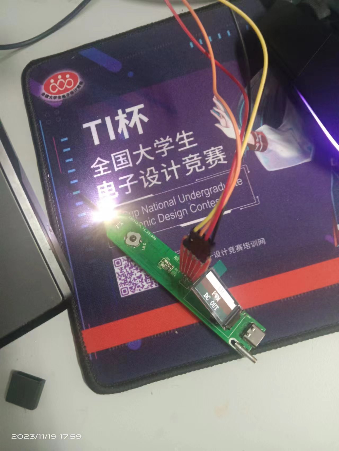 I thought that would be enough, but then another problem arose. After soldering, it wouldn't turn on at all. So I analyzed all the digital circuits, checking all the problems one by one, and finally found that the linear regulator was faulty.
 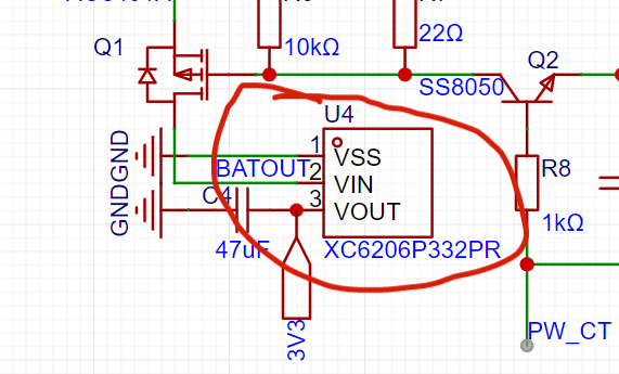 The input was 4V and the output was 0.3V, so I replaced the regulator, and it worked. The multi-function pen could also turn on correctly. However, I later found that there was a white line on the screen, indicating that the program hadn't been burned. So I adjusted it. If your screen also has a line, you can adjust it like I did. Please
 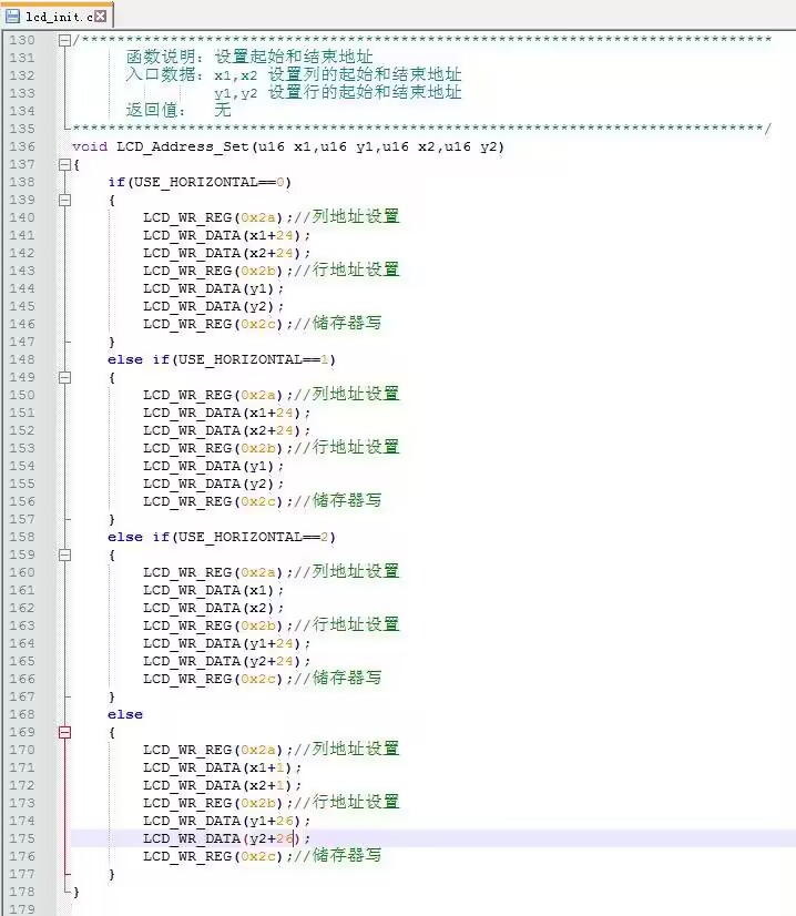 modify the image below to match the original image, that is, change the original 24 to 26 and change X to X+1. I hope this helps.
All reference designs on this site are sourced from major semiconductor manufacturers or collected online for learning and research. The copyright belongs to the semiconductor manufacturer or the original author. If you believe that the reference design of this site infringes upon your relevant rights and interests, please send us a rights notice. As a neutral platform service provider, we will take measures to delete the relevant content in accordance with relevant laws after receiving the relevant notice from the rights holder. Please send relevant notifications to email: bbs_service@eeworld.com.cn.
It is your responsibility to test the circuit yourself and determine its suitability for you. EEWorld will not be liable for direct, indirect, special, incidental, consequential or punitive damages arising from any cause or anything connected to any reference design used.
Supported by EEWorld Datasheet
EEWorld
subscription
account

EEWorld
service
account

Automotive
development
community

Robot
development
community

About Us Customer Service Contact Information Datasheet Sitemap LatestNews


Room 1530, 15th Floor, Building B,
No.18 Zhongguancun Street,
Haidian District,
Beijing, Postal Code: 100190
China
Telephone: 008610 8235 0740
 京公网安备 11010802033920号

 AM27C512-70DC


