 Therefore, I drew the core board's components and packages in EDA, directly referencing the Hardwood Classroom's pin layout for software compatibility.
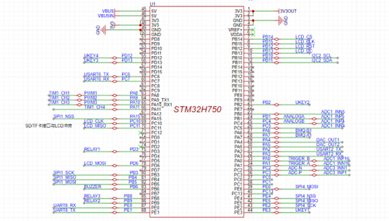
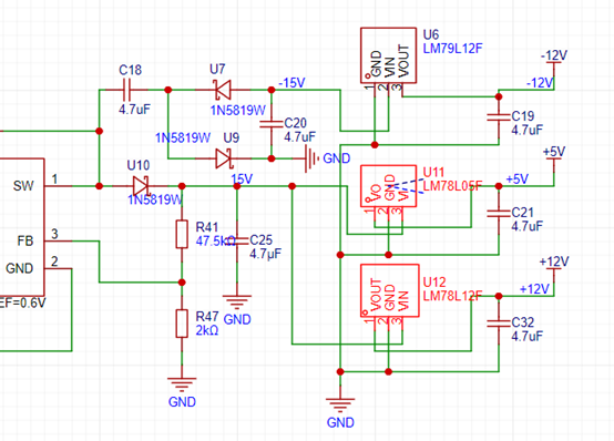 2. The PCB
 3. Components and Soldering:
 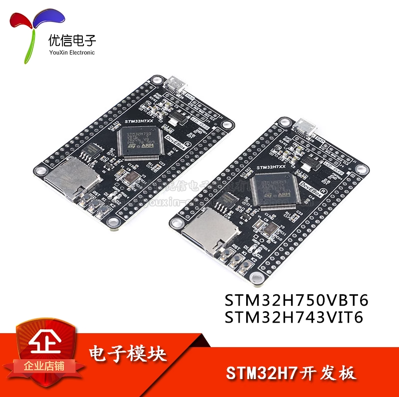 2.8-inch TFT Screen:
  All other components were purchased from LCSC.
 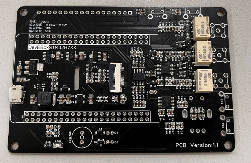 solder joints, use a soldering iron to adjust them. However, note that there are several NC components in the schematic that don't require soldering.
 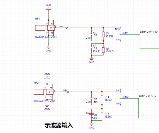 4. 3D Shell
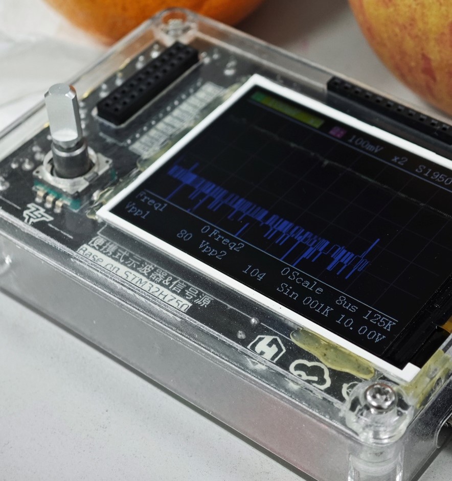
  I managed to get it done, albeit with some difficulty. For the printing material, I chose the most expensive transparent resin for aesthetics. Surprisingly, the final product from 3D Monkey turned out quite well, with very high transparency. The screen was directly fixed with hot melt glue, but the aged yellow glue was unsightly…
 5. Software and Programming
  Since I used the STM32H750 core board and didn't have an STLink programmer, I used the built-in DFU programming function. I used DFU File Manager to convert the hex file to a dfu file. By connecting the BTO pin to 3V3 to start DFU Mode, connecting the core board to the computer, and then downloading via DfuSe Demo,
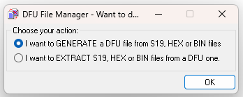
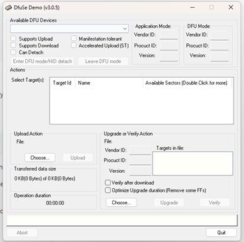 the programming process was surprisingly smooth. After the program was written, waveforms were displayed directly, and the input of each HMI button and knob worked without issue.
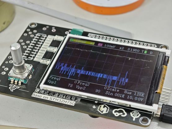


All reference designs on this site are sourced from major semiconductor manufacturers or collected online for learning and research. The copyright belongs to the semiconductor manufacturer or the original author. If you believe that the reference design of this site infringes upon your relevant rights and interests, please send us a rights notice. As a neutral platform service provider, we will take measures to delete the relevant content in accordance with relevant laws after receiving the relevant notice from the rights holder. Please send relevant notifications to email: bbs_service@eeworld.com.cn.
It is your responsibility to test the circuit yourself and determine its suitability for you. EEWorld will not be liable for direct, indirect, special, incidental, consequential or punitive damages arising from any cause or anything connected to any reference design used.
Supported by EEWorld Datasheet
EEWorld
subscription
account

EEWorld
service
account

Automotive
development
community

Robot
development
community

About Us Customer Service Contact Information Datasheet Sitemap LatestNews


Room 1530, 15th Floor, Building B,
No.18 Zhongguancun Street,
Haidian District,
Beijing, Postal Code: 100190
China
Telephone: 008610 8235 0740
 京公网安备 11010802033920号

 1.5KE68CA-A


