

PDF_TPA3118ClassDAudioAmpTestBoard-V2.zip
Altium_TPA3118ClassDAudioAmpTestBoard-V2.zip
PADS_TPA3118ClassDAudioAmpTestBoard-V2.zip
97262
The Mate 60 Pro NFC card is far ahead of its competitors.
A simple NFC chip, with a leading-edge outer casing printed in color.
The NFC card, far ahead of its competitors
, needs no further explanation. The circuit diagram above


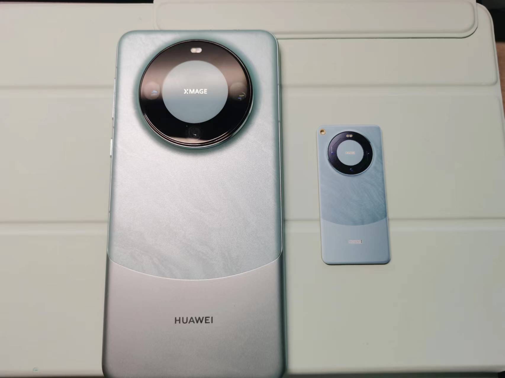
is very simple and virtually identical to all open-source NFC cards available online.
It has already been tested and is usable.
PDF_The Leading Mate 60 Pro NFC Card.zip
Altium_Leading the Way Mate 60 Pro NFC Card.zip
PADS_Leading the Way Mate 60 Pro NFC Card.zip
BOM_The Leading Mate 60 Pro NFC Card.xlsx
97263
Desktop step-up/step-down UPS power supply
It uses the XL6009 chip and SEPIC circuit, and has both boost and buck capabilities. The input voltage is 3.5~20V (the maximum voltage can be increased, requiring a higher voltage capacitor), the output voltage is 1.26~20V, and the maximum current is 4A.
To facilitate circuit board debugging, a power supply with multiple voltage options is typically required. Therefore, this power supply was created. Its main functions are as follows: 1) Input: Type-C, DC plug, 18650 battery; 2) Output: DC 1.26-26V, current Max=4A, interface: USB-A, pH terminal, pin header. The main features of this circuit are the use of the XL6009 chip and SEPIC circuitry, providing step-up/step-down capability. The input voltage is 3.5~20V (the maximum voltage can be increased by matching a higher voltage capacitor). The layout of the FB and SW terminals has been meticulously designed. Actual testing shows that the output voltage meets the above requirements, and it has strong load capacity (continuous operation of a 20W motor load does not generate excessive heat).
PDF_Desktop Step-Up/Step-Down UPS Power Supply.zip
Altium Desktop Buck-Boost UPS Power Supply.zip
PADS_Desktop Step-Up/Step-Down UPS Power Supply.zip
BOM_Desktop Step-Up/Step-Down UPS Power Supply.xlsx
97265
thermal imager
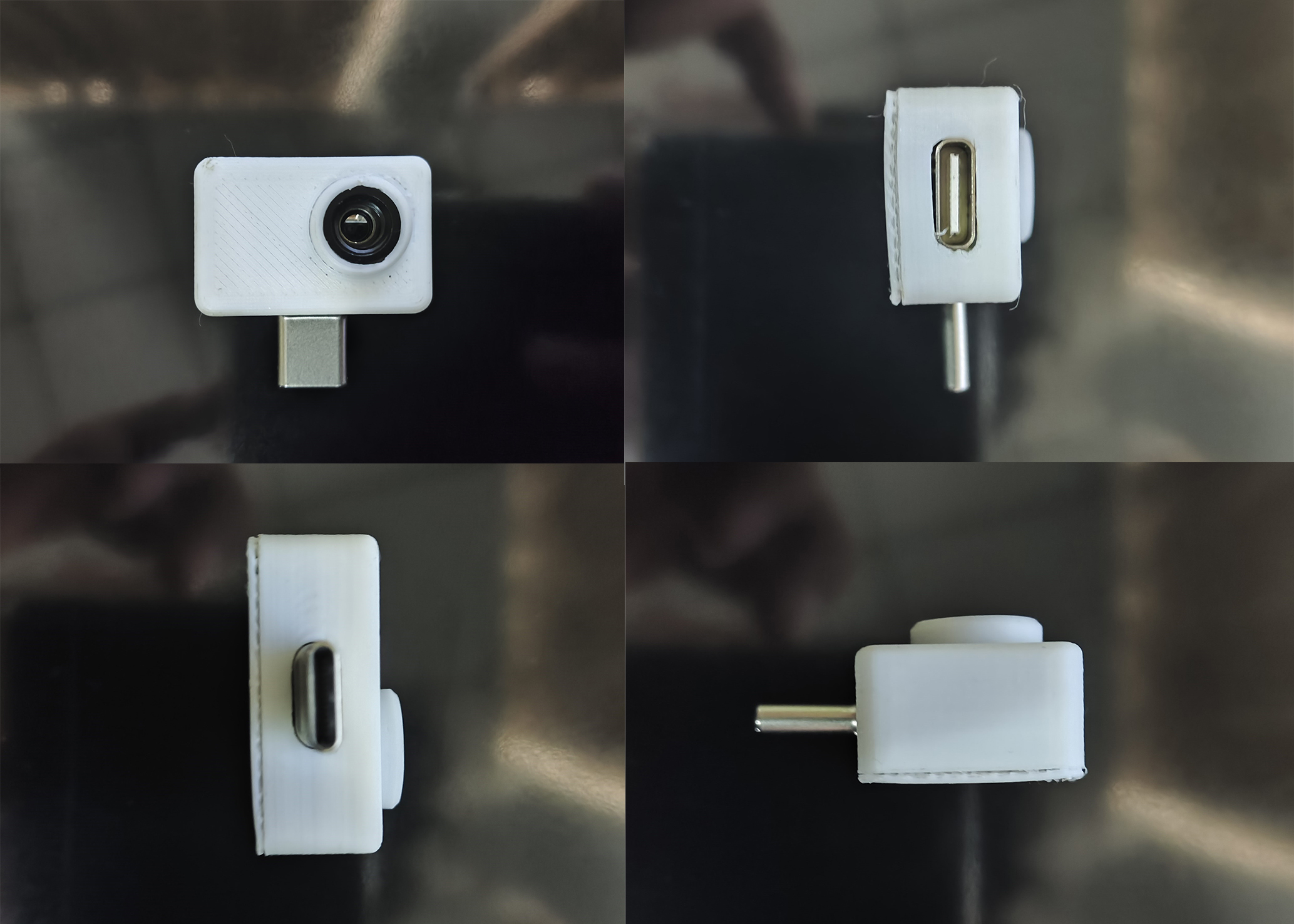
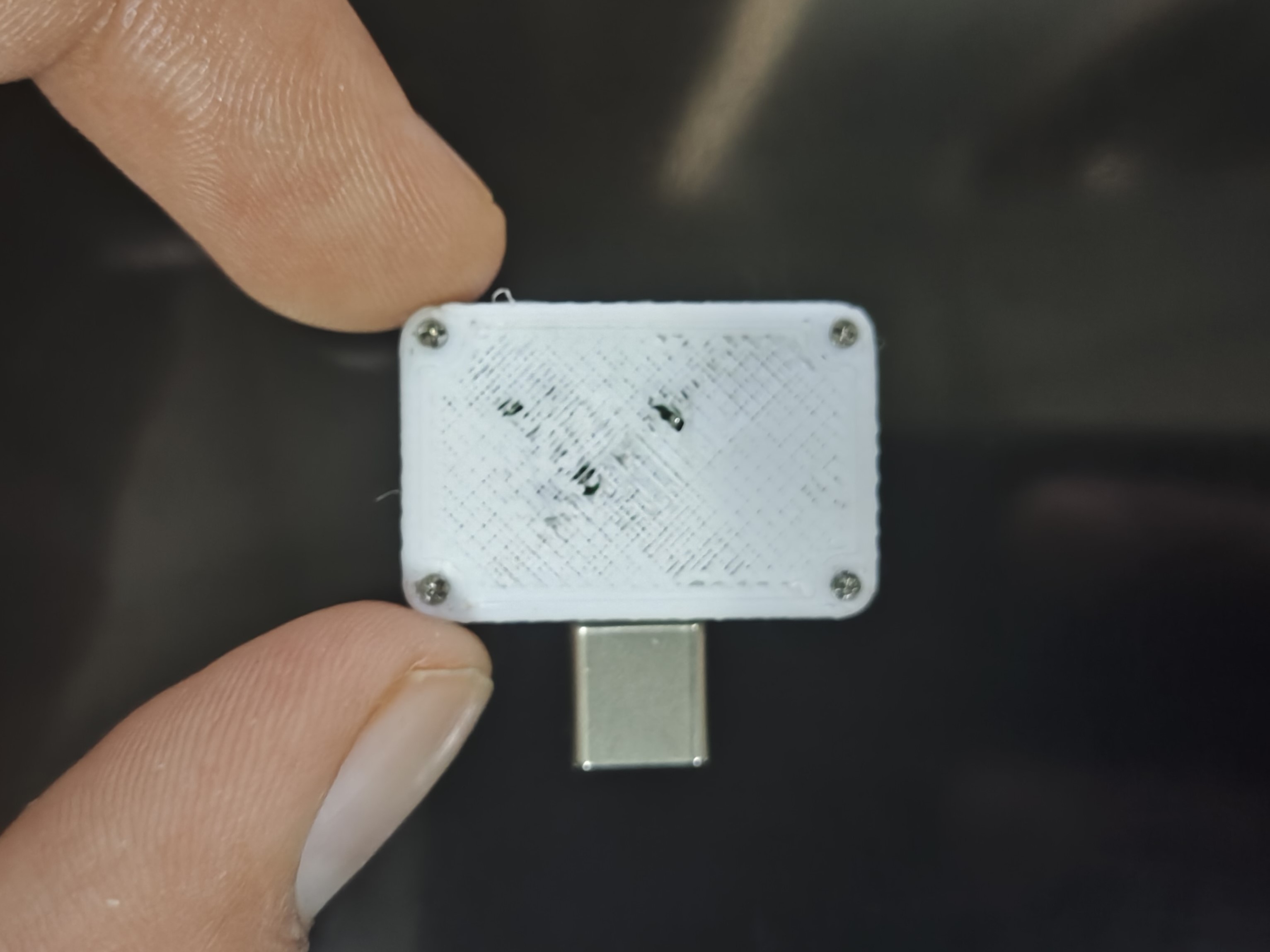
The thermal imager was redesigned and 3D printed to make it a more compact, portable, and aesthetically pleasing finished product!
Project Source
: 【Ultra-Small】Infrared Thermal Imager 1 - JLCPCB EDA Open Source Hardware Platform (oshwhub.com).
I only modified the PCB appearance of this project. For details, please see the link above or the source project link: https://github.com/huxiangjs/hoozz_play.
Source Author Video: 【Implementing Mobile Phone Thermal Imaging Hoozz Play - MLX90640】 https://www.bilibili.com/video/BV1qh4y1v7mr.
Rendering and Display.

3D Structure

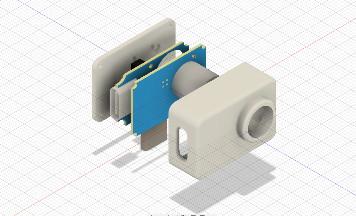
and Physical Display.
Due to a sudden malfunction of the 3D printer, the back cover was not properly made and looks a bit ugly. It is recommended to apply some B7000 glue.
Step 1: Direct Insertion and Connection
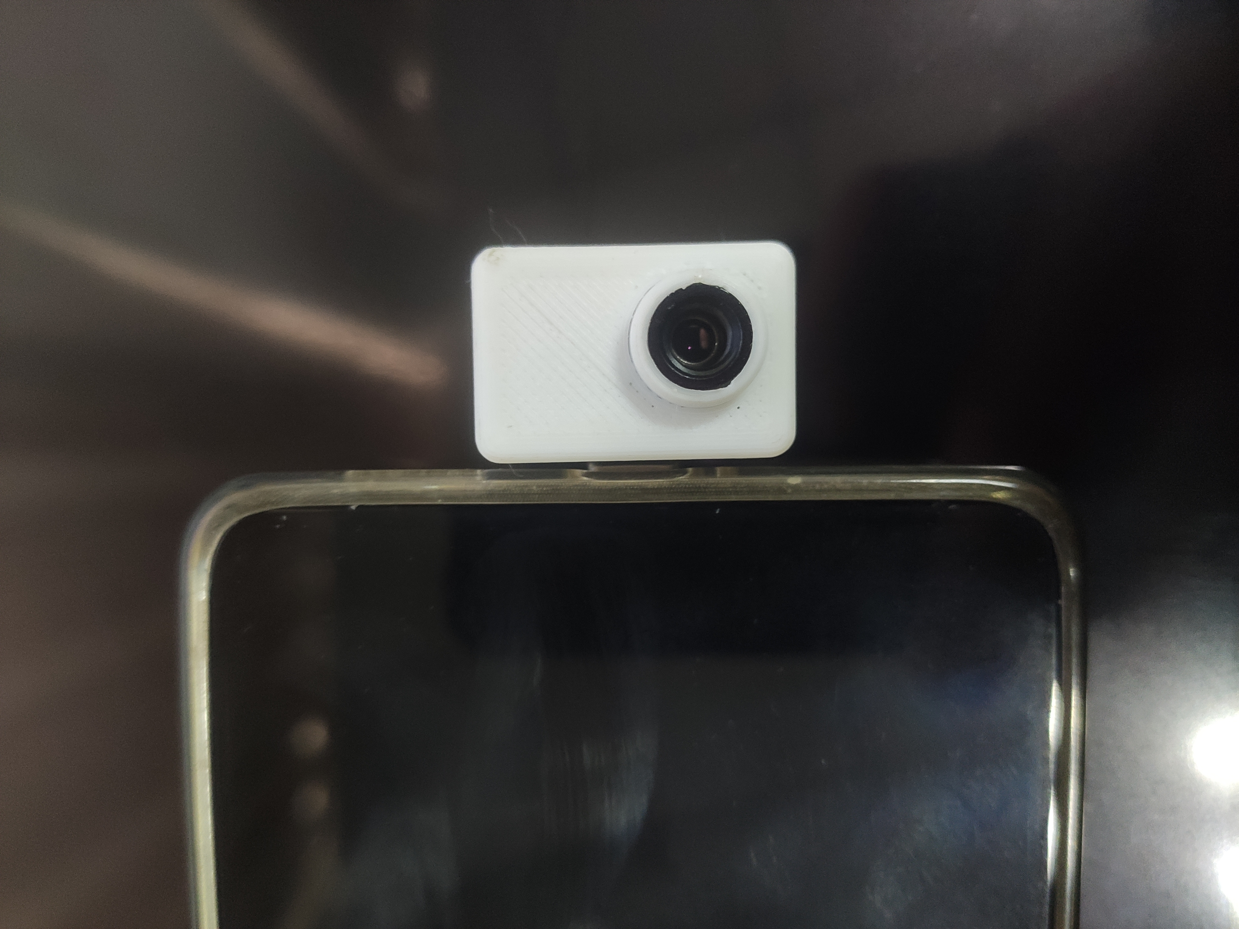
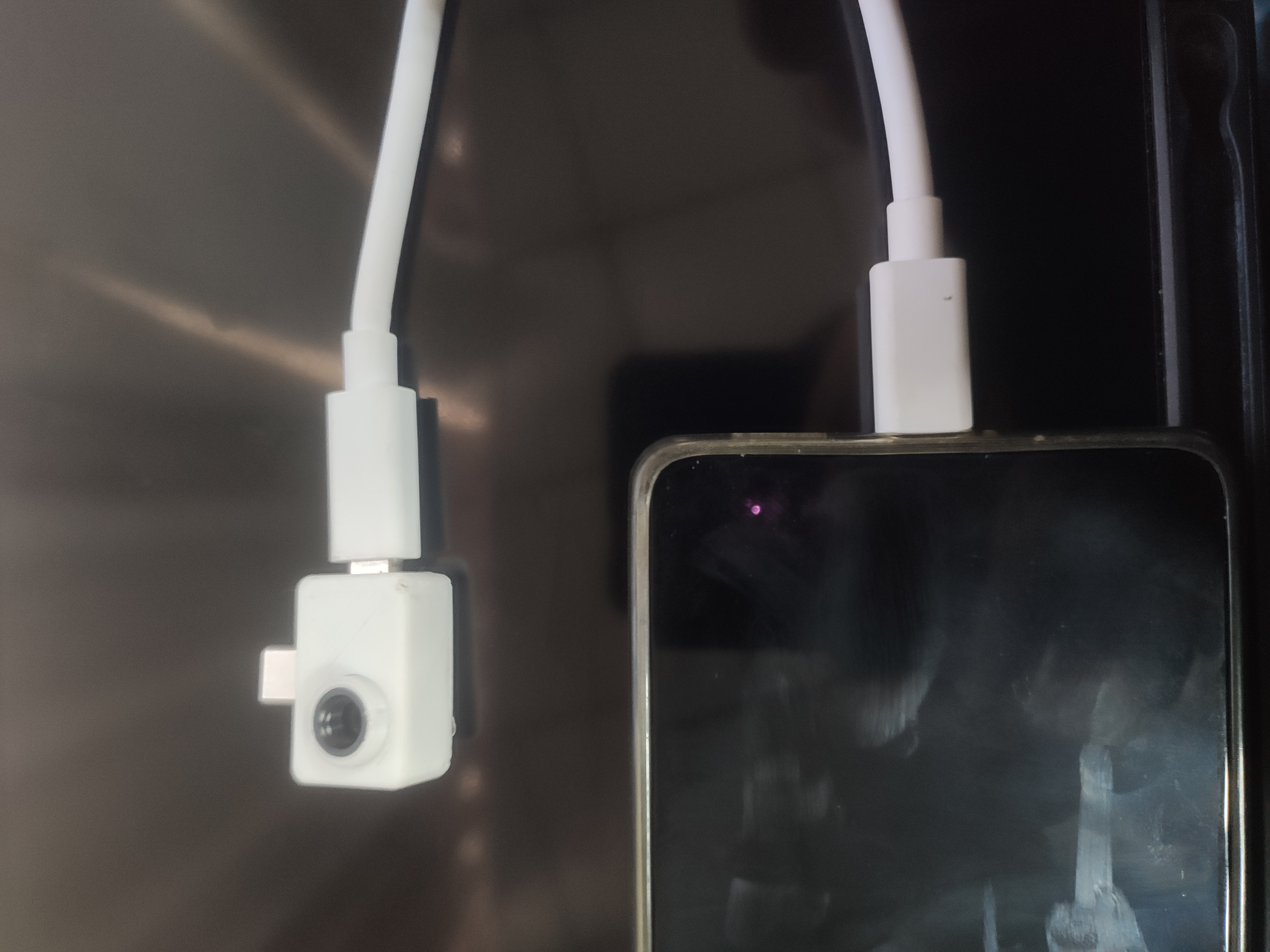
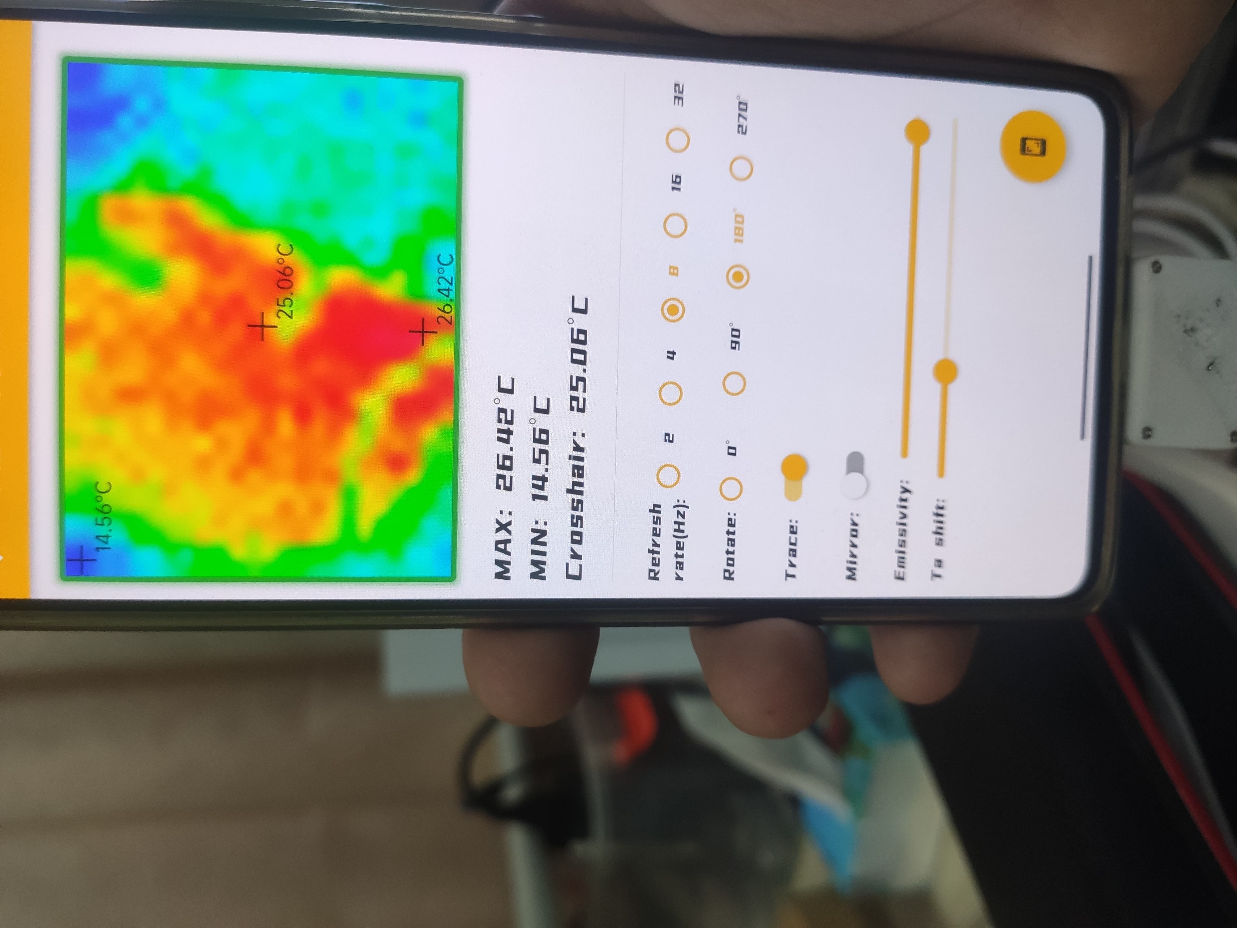
Function Demonstration.
Using my computer case as a reference.
Tutorial:
1. Material Preparation:
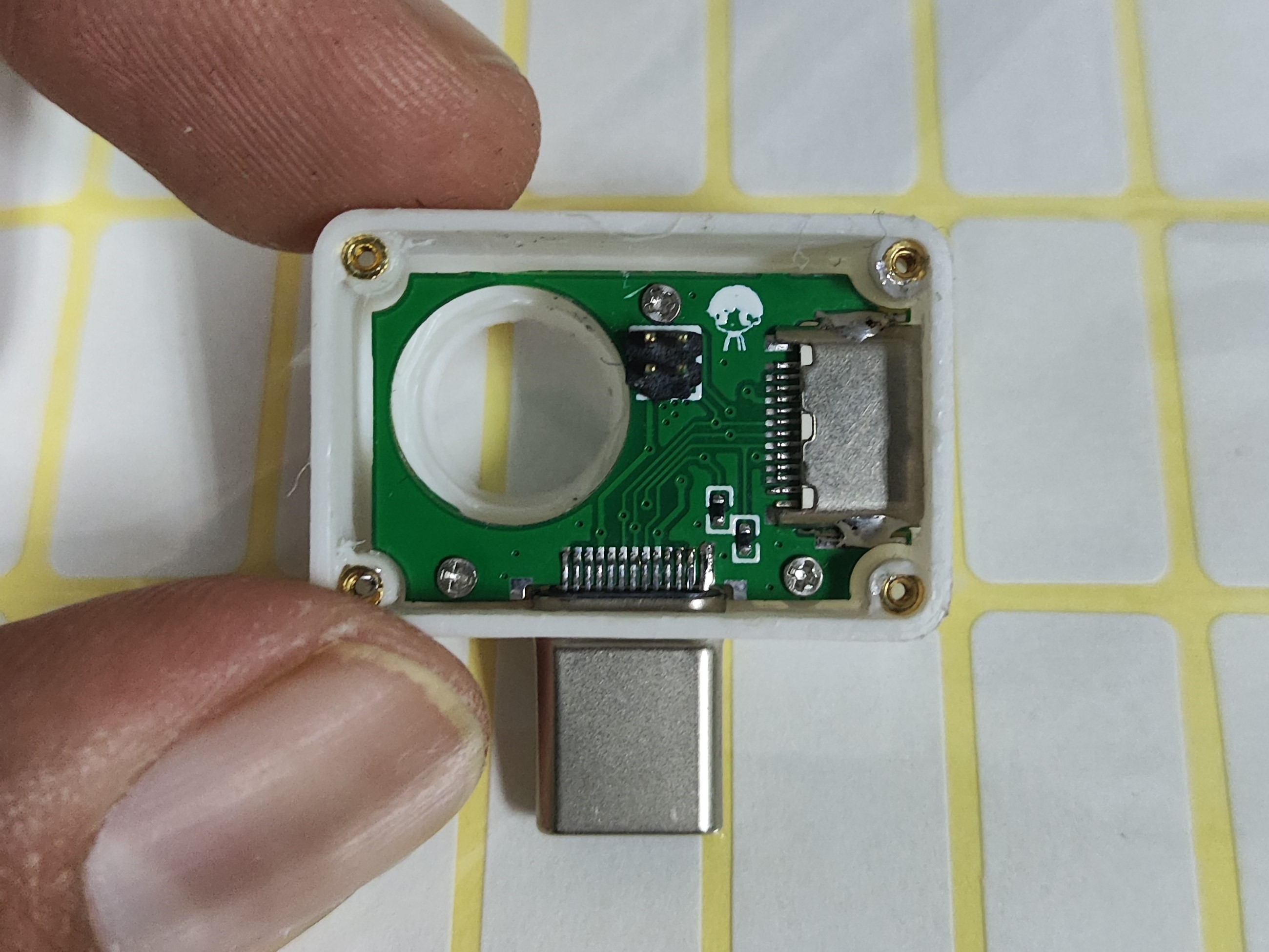
Solder the components according to the PCB (do not solder the CC2 resistor and header pins here), and burn the firmware into it. The pull-down resistor on the left side does not need to be soldered!
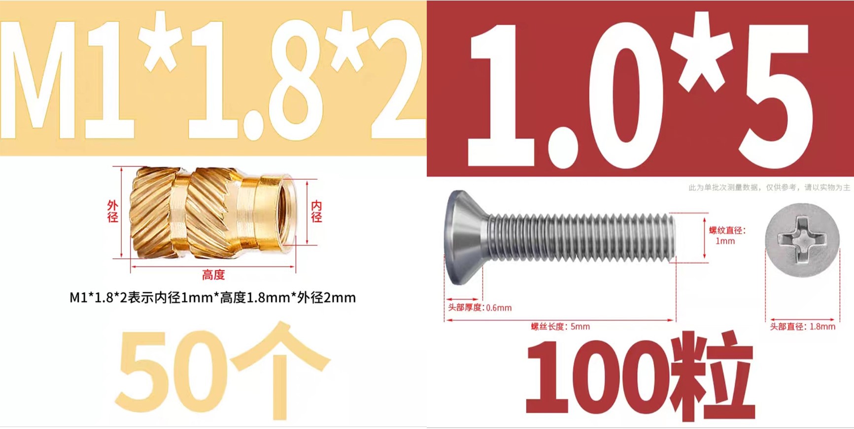
Inject the T-shaped nut into the 3D shell. You can use a soldering iron here, set the temperature to about 120℃, and carefully inject the nut into the 3D shell (care is required).
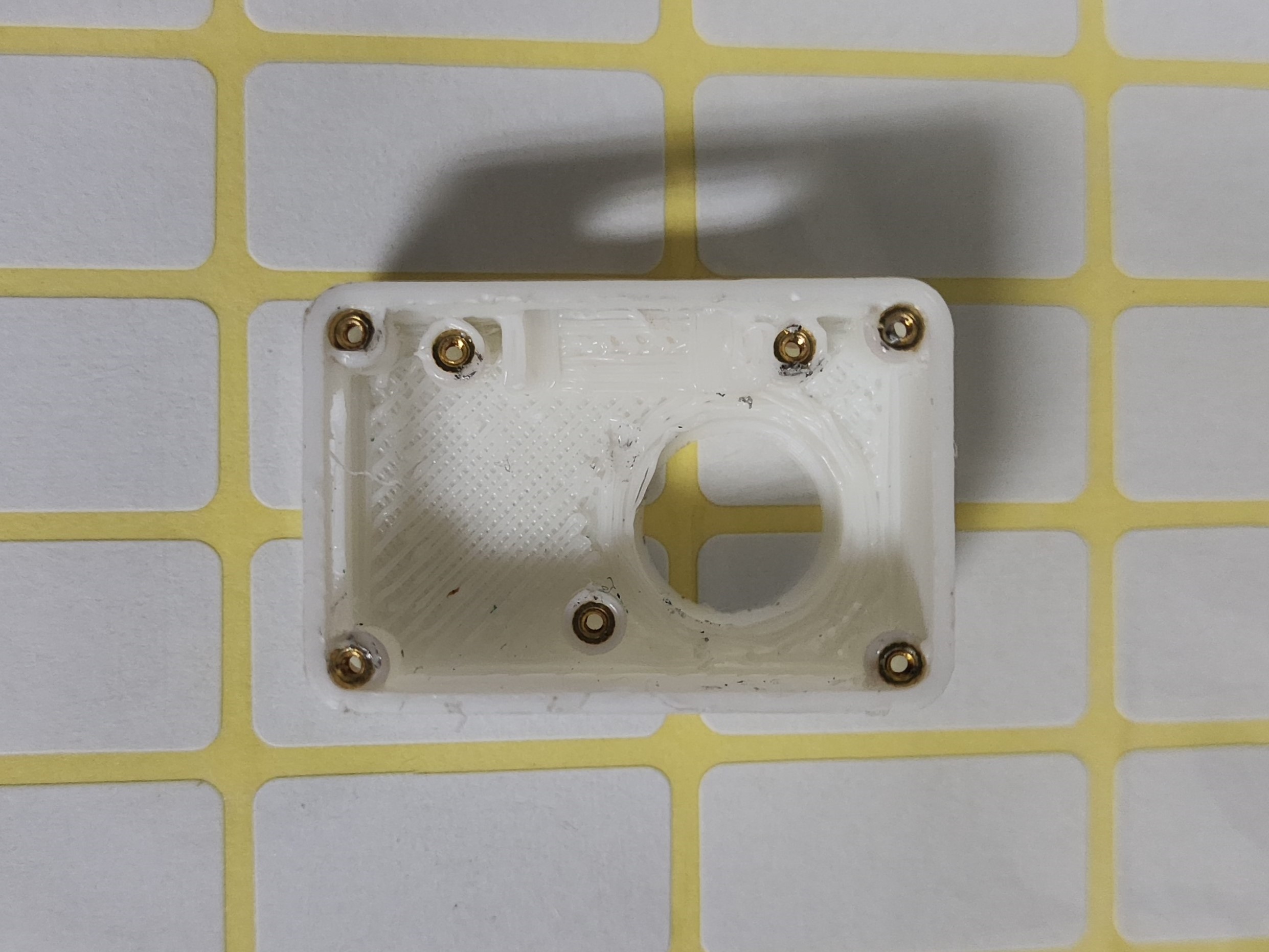
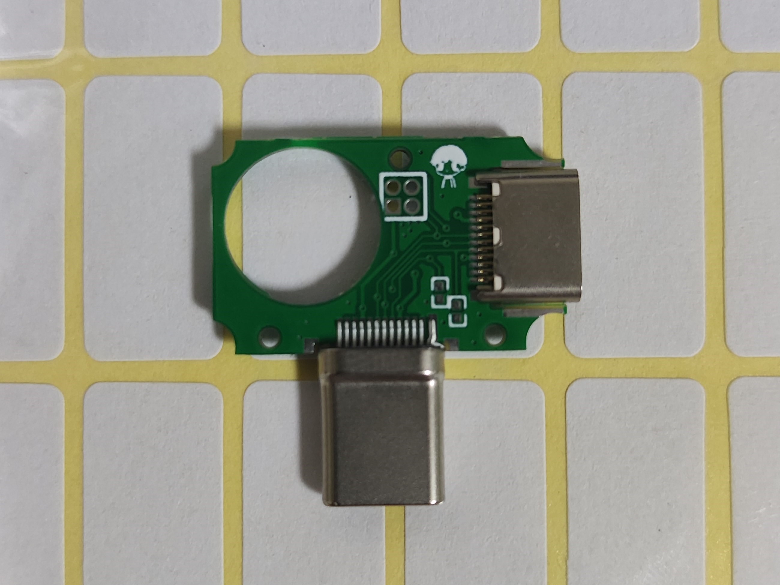
First, solder the pin headers to the Type-C board (the first PCB). This is crucial; adjust the pin header length so that they are just exposed on the second PCB (the one with the main controller and sensors) for easy installation of the back cover. See the pin header port in the second image. (If you don't understand, continue reading.)
Next, install the first board into the 3D housing. This requires a little skill. Then, tighten the screws.

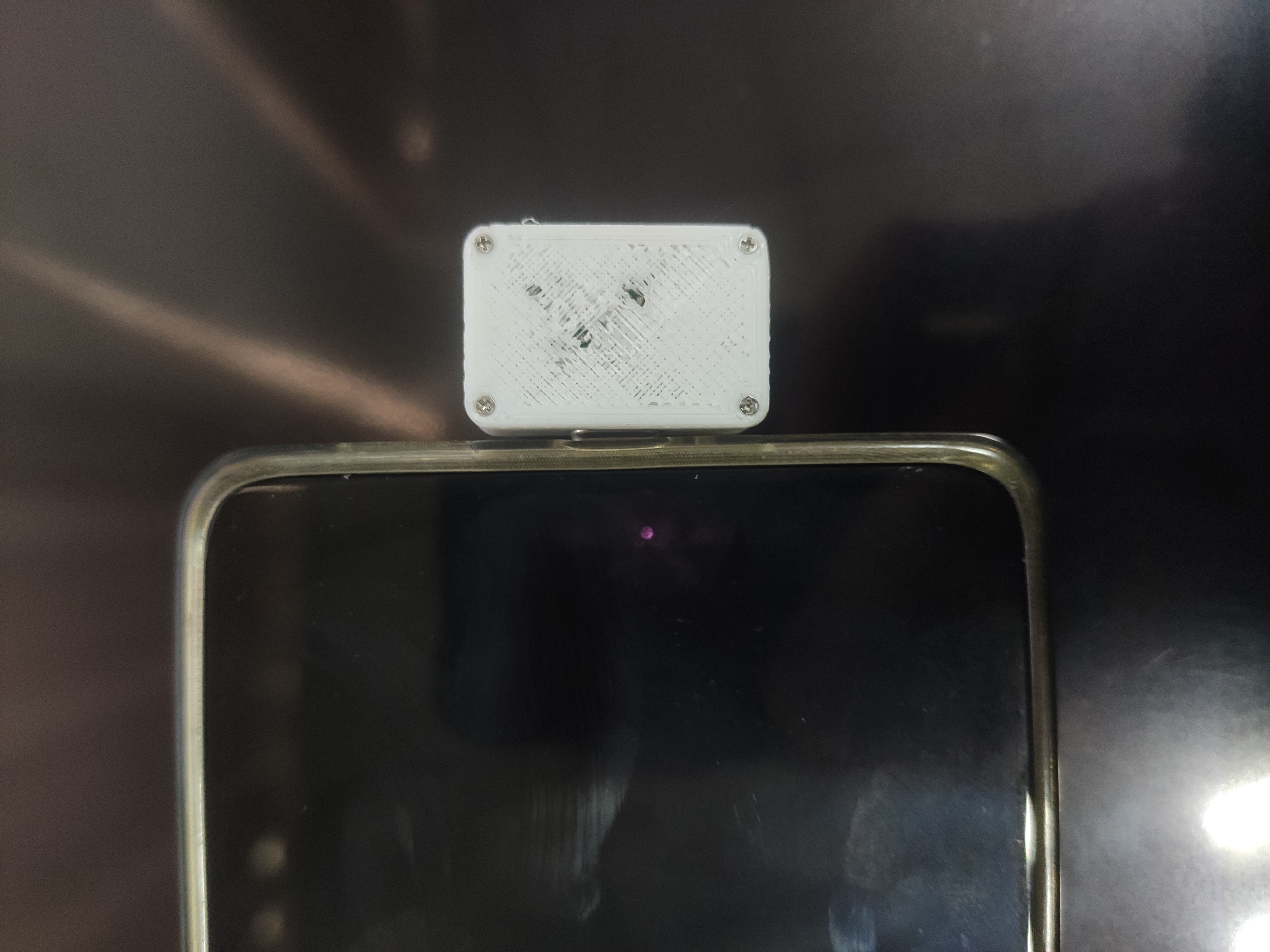
The back cover has been slightly recessed where there is solder. You can apply a little B7000 glue to the edge of the back cover before screwing in the four screws.
Here, the back cover flew off, and the 3D printer collapsed!
Manufacturing Instructions:
1. Select a board thickness of 0.8mm
. 2. The board has already been assembled in the project.
3. The thermal imaging sensor has been rotated at a slight angle; the initial design using the default angle resulted in a rotated image
. 4. The CC2 resistor does not need to be soldered.
5. Before inserting the phone, ensure that VCC and GND are not short-circuited (measured with a multimeter), and that the LDO input is approximately 5V and the LDO output is 3.3V (tested with a power bank and measured with a multimeter) to avoid potential damage to your property.
6. Please be aware!
3D Shell.zip
Photos.zip
PDF_Thermal Imager.zip
Altium_thermal_imager.zip
PADS_Thermal Imaging Device.zip
BOM_Thermal Imaging Device.xlsx
97266
Ultrasonic transducer circuit experiment
Ultrasonic transducer circuit based on 51 microcontroller
Objective: To enable continuous operation of the ultrasonic transducer via continuous pulses. The microcontroller detects when a button is pressed and emits a square wave at a frequency of 500kHz. The duty cycle (from 10% to 90%) is controlled by a detection potentiometer.
PDF_Ultrasonic Transducer Circuit Experiment.zip
Altium_Ultrasonic Transducer Circuit Experiment.zip
PADS_Ultrasonic Transducer Circuit Experiment.zip
BOM_Ultrasonic Transducer Circuit Experiment.xlsx
97267
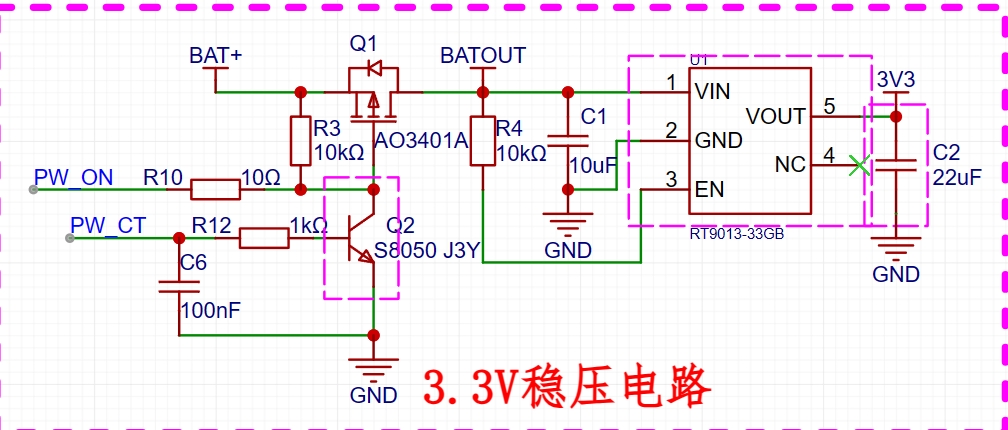
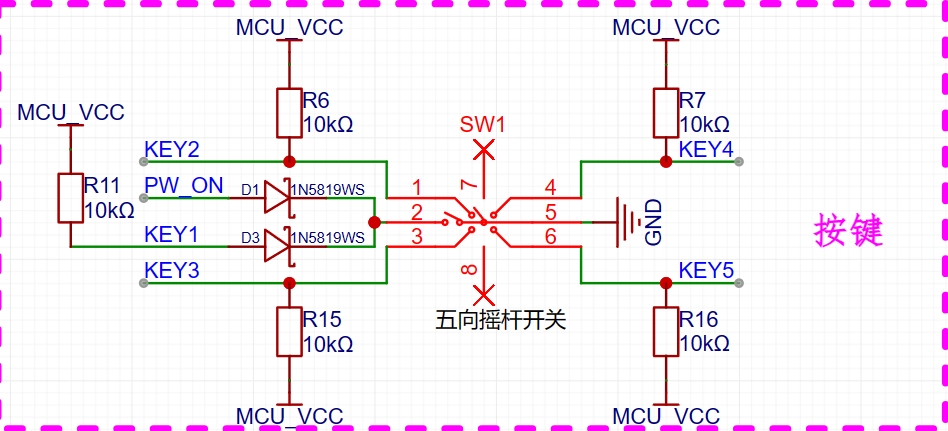
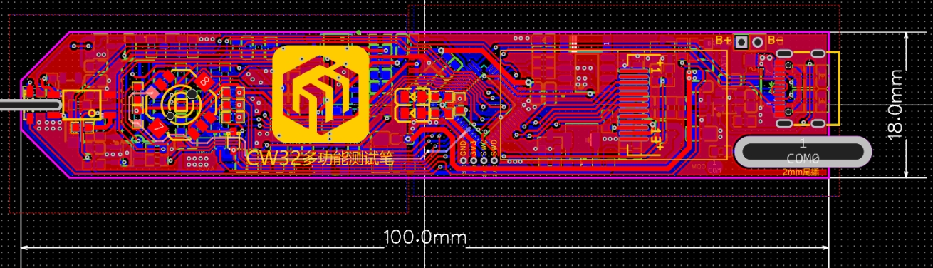
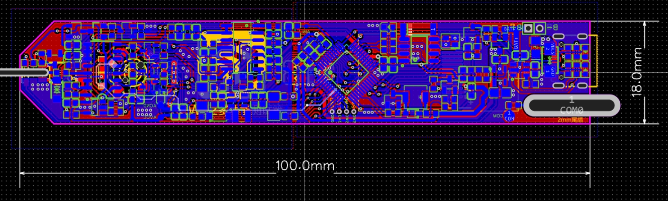
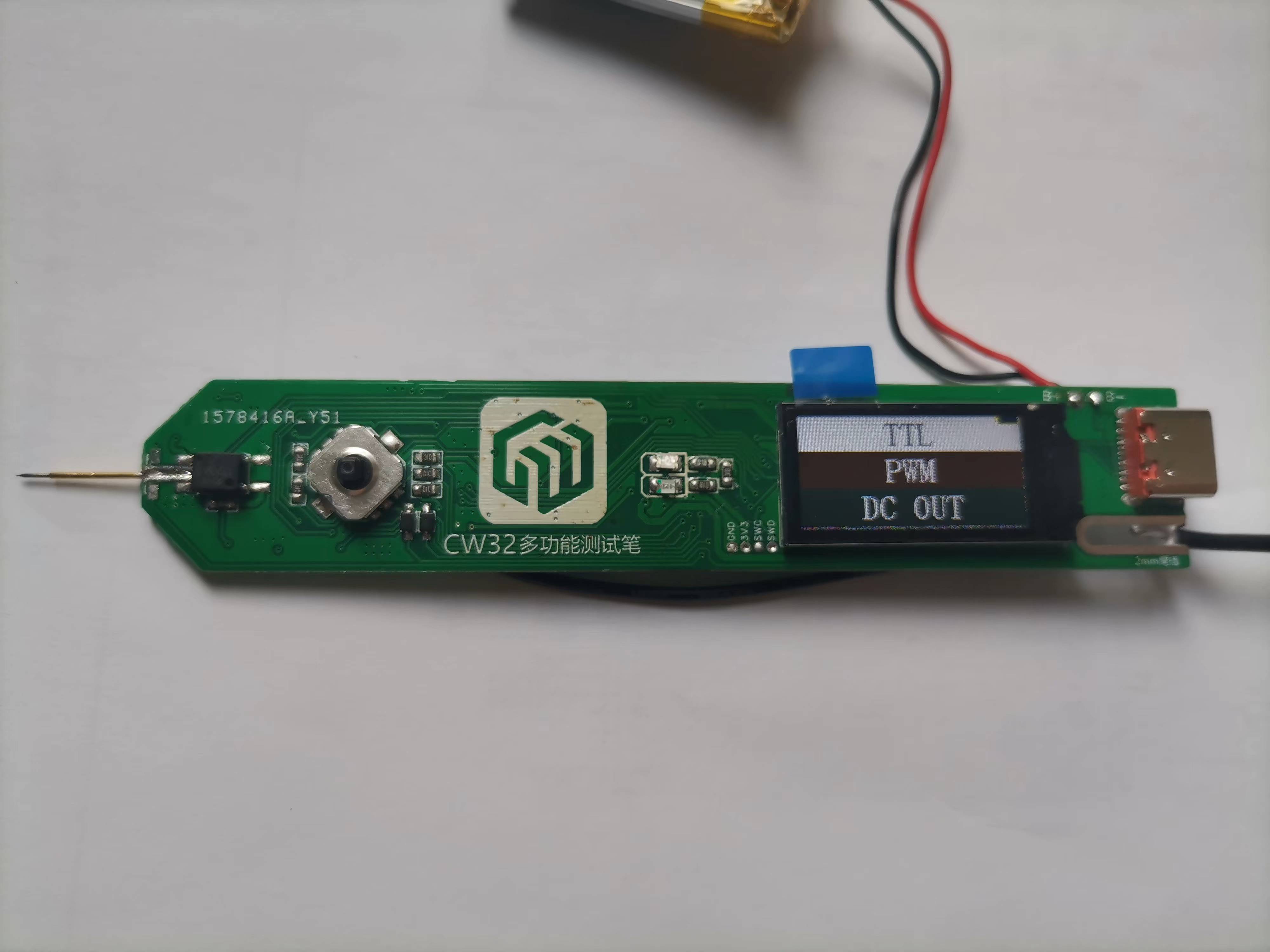
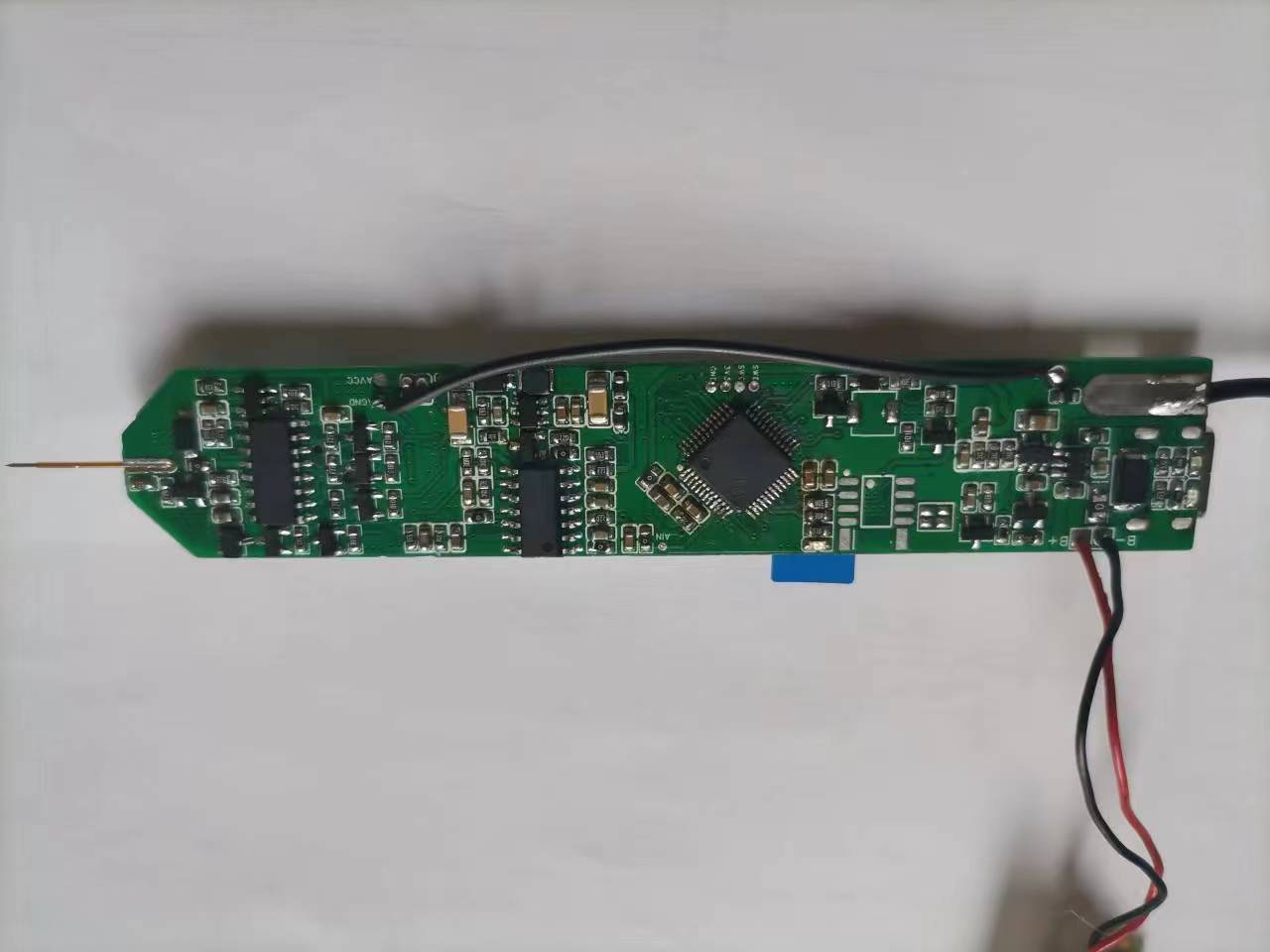
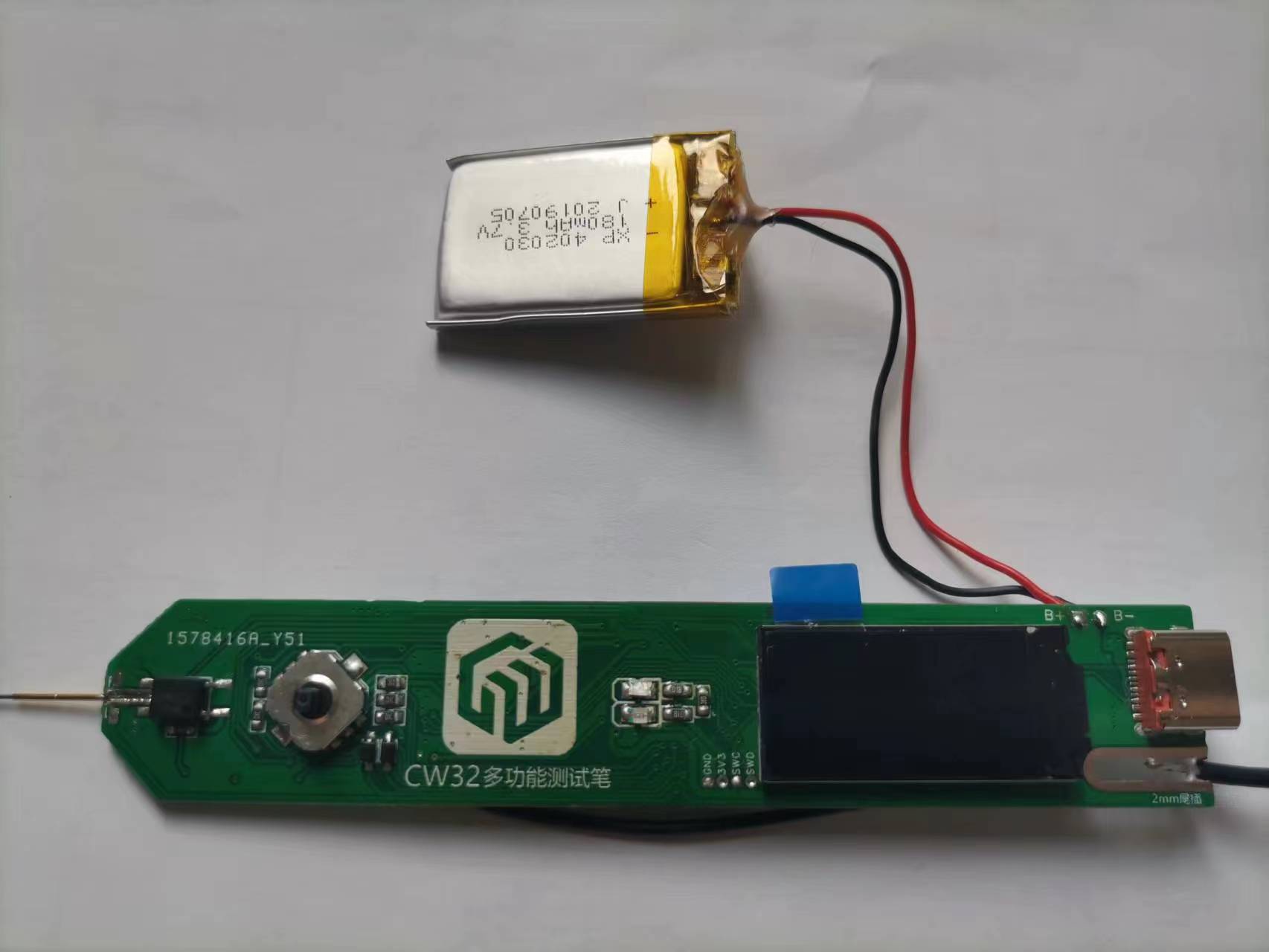
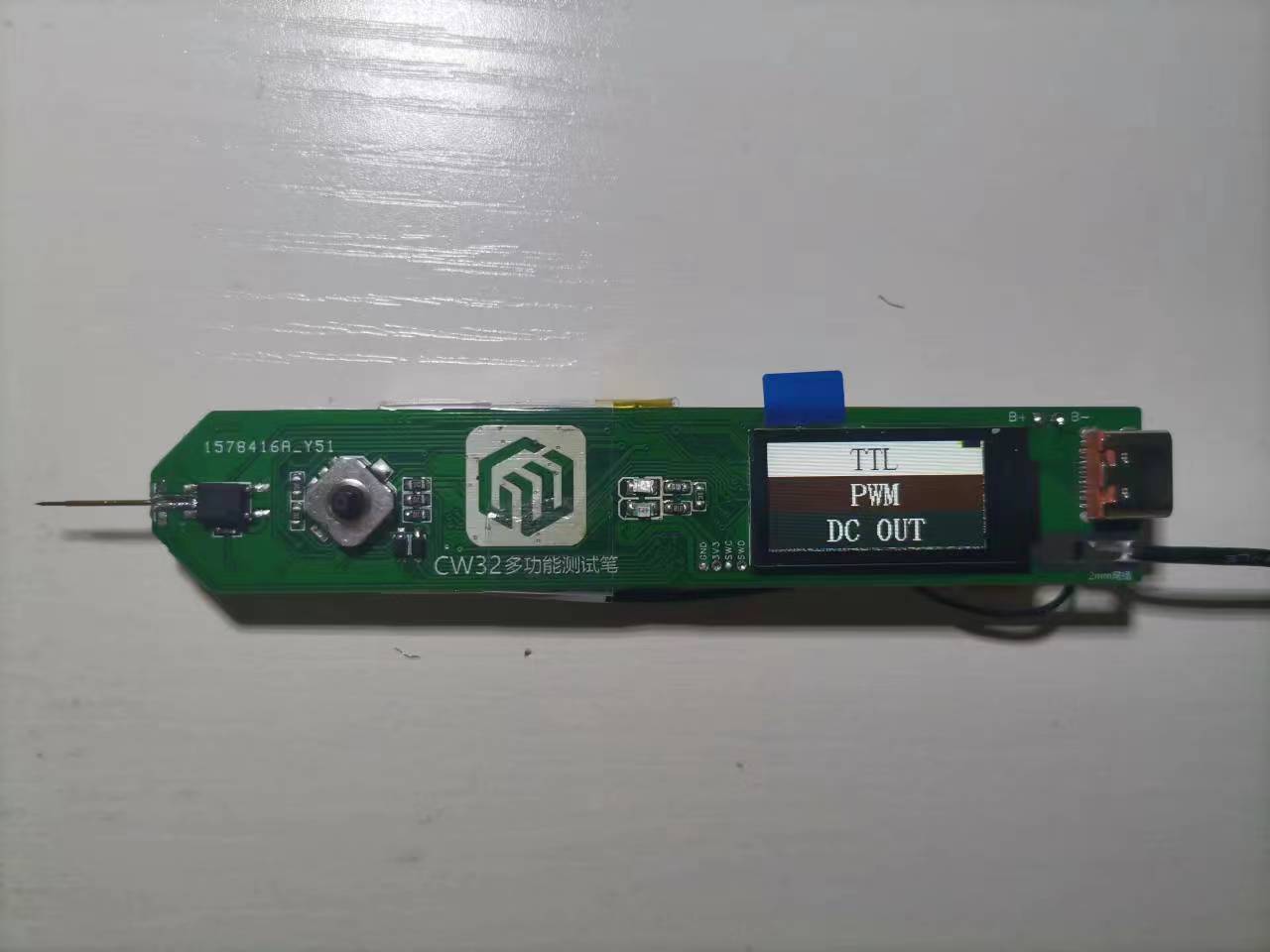
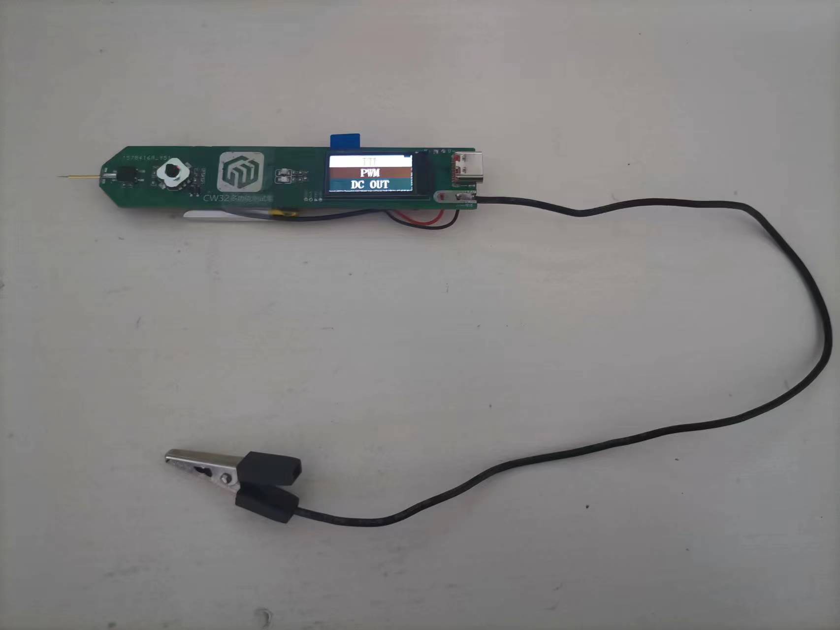
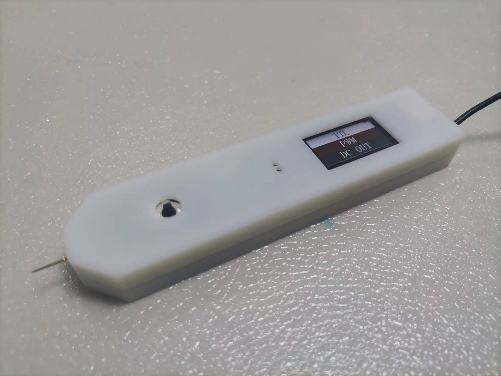
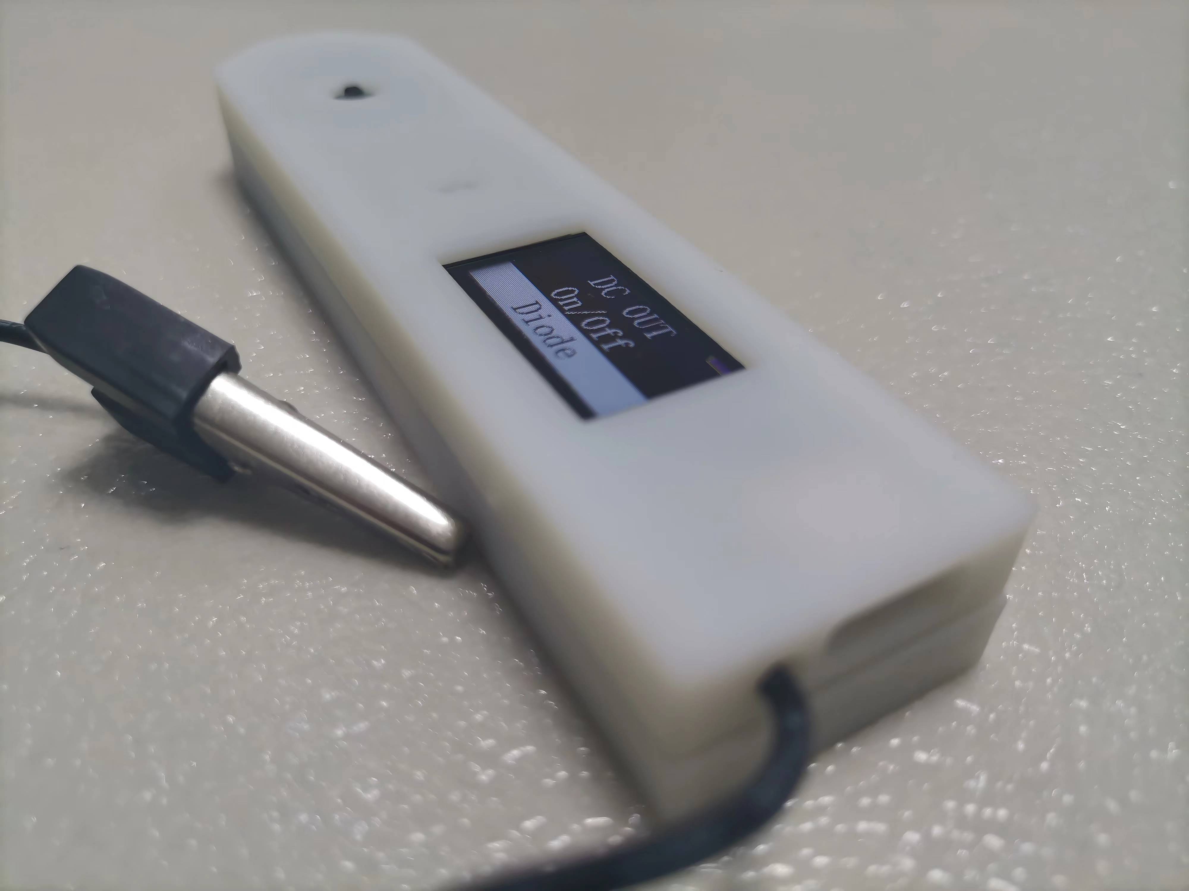
Multifunctional test pen (based on CW32)
Based on the CW32 multi-functional test pen, the product has been verified to be usable.
4e5d342b7daf84ab9199bef7d8d2d877.mp4
test_pen-master.zip
PDF_Multifunctional Test Pen (based on CW32).zip
Altium Multi-functional Test Pen (based on CW32).zip
PADS Multifunctional Test Pen (based on CW32).zip
BOM_Multifunctional Test Pen (Based on CW32).xlsx
97268
Liclock Improved-1
Based on the work of Xiao Li's Electronics Lab, improvements were made by replacing the originally difficult-to-solder QFN chip with a more easily solderable SOP chip. The relevant resistor configurations were modified according to the instructions, and the system successfully ran.
Original project address: oshwhub.com/lxu0423/ESP32-duo-gong-neng-mo-shui-ping
Tutorial address
: blog.csdn.net/qq_51427262/article/details/134097200?spm=1001.2014.3001.5501
PDF_Liclock Improved Version-1.zip
Altium_Liclock Improved Version-1.zip
PADS_Liclock Improved Version-1.zip
97269
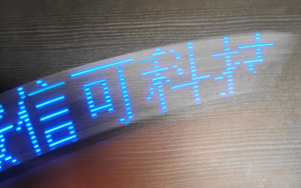
LED rocker
AI-M61-32S-kit Shaker
This is a small toy I made using the Ai-M61-32S-kit development board. It can display graphics or text by shaking it left and right. It's very simple. If you like, you can make one and play with it.
Required materials:
1 vibration sensor, soldered to the infrared part, 16 0603 package resistors and 16 0805 LEDs.
PDF_LED Shaker.zip
Altium_LED shaker.zip
PADS_LED Shaker.zip
BOM_LED Shaker.xlsx
97271
electronic

 The casing was designed using LCSC EDA.
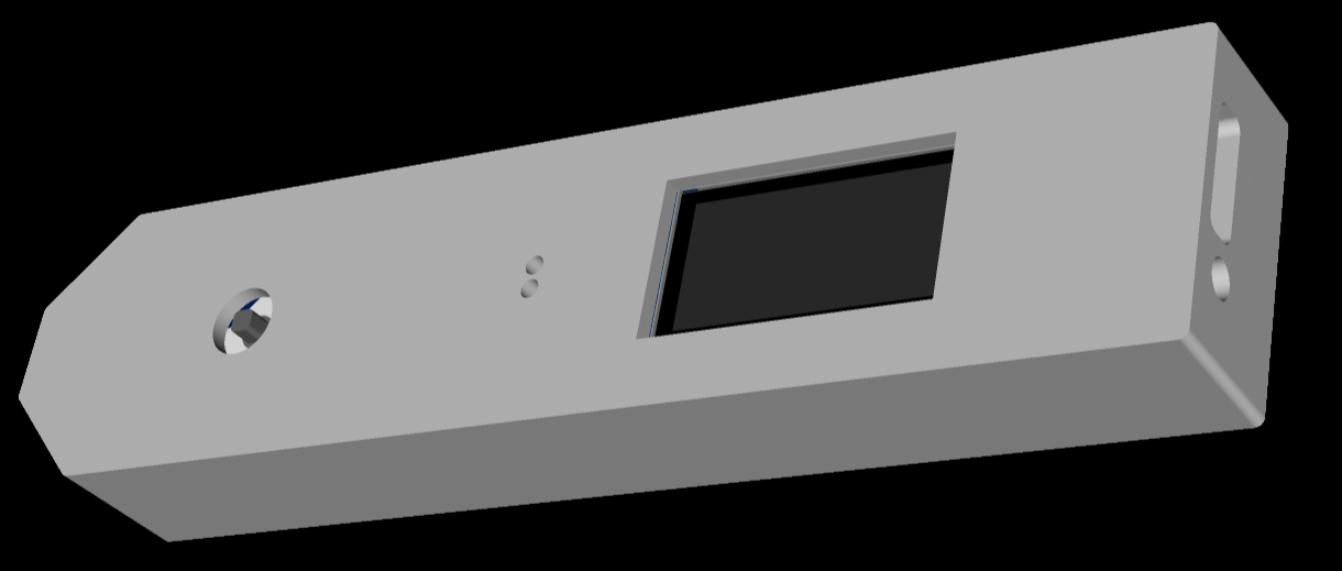


 京公网安备 11010802033920号

 10DF1
10DF1


