1. Raindrop Sensor:
Raindrop sensors are used to detect whether it is raining and the amount of rain. They are mainly used in automotive intelligent lighting (AFS) systems, automatic windshield wiper systems, and intelligent window systems. The raindrop sensor is basically a plate with nickel coated in a linear pattern. The common working principle of raindrop sensors is to determine whether it is raining by detecting the conductivity of water droplets. It uses the change in conductivity between two electrodes to measure the presence of water droplets. There is an air gap between these two electrodes, which is normally an open circuit. When a water droplet comes into contact with the electrodes, the conductivity of the water droplet causes current to flow through the droplet, forming a current loop, thereby changing the resistance between the electrodes. This changes the voltage drop across them.


This design only uses the AO interface connected to the PF8 pin of the microcontroller, using channel 6 of ADC2.
2. Photoresistor Sensor:
Photoresistors are special resistors made of semiconductor materials such as silicide or selenide. Their working principle is based on the internal photoelectric effect. As light intensity increases, the resistance value decreases rapidly. Since the charge carriers generated by light participate in conduction, they drift under the influence of an applied electric field. Electrons move towards the positive terminal of the power supply, and holes move towards the negative terminal, causing the resistance of the photoresistor to drop rapidly. In the absence of light, it exhibits almost high resistance, and its resistance is very high in the dark. Photoresistor modules are generally used to detect the brightness of ambient light and trigger microcontrollers or relay modules.

This design uses an AO interface connected to the PF6 pin of the microcontroller, utilizing channel 4 of ADC2.
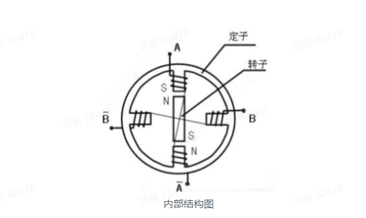
3. Stepper Motor A
stepper motor is an open-loop controlled motor that converts electrical pulse signals into angular or linear displacement; it is also called a pulse motor. The most important components of a stepper motor are the rotor and stator. The stator controls the direction of the magnetic field with current, generating magnetic force when energized. The rotor, surrounded by the stator, rotates due to changes in the stator's magnetic field. By energizing the stator, a magnetic force is generated, attracting the rotor, causing it to rotate a small increment. Continuous energization of the stator allows the rotor to rotate. Under non-overload conditions, the motor's speed and stopping position depend solely on the frequency and number of pulse signals. When the stepper driver receives a pulse signal, it can drive the stepper motor to rotate a fixed angle in a set direction.
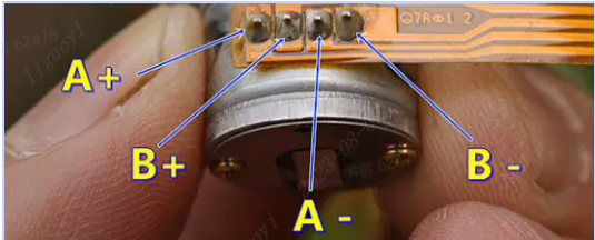
A two-phase four-wire stepper motor, where "two-phase" refers to two coils and "four-wire" refers to two wires per coil. A+ and A- form one phase, and B+ and B- form another.
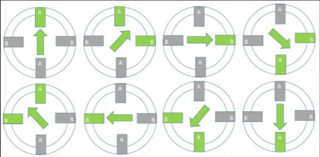
To make it rotate, the coils need continuous energization. There are four-step and eight-step rotation modes. This design uses the eight-step mode. The rotation sequence in the eight-step mode is: [A+]->[A+B+]->[B+]->[B+A-]->[A-]->[AB-]->[B-]->[B-]->[B-A+].
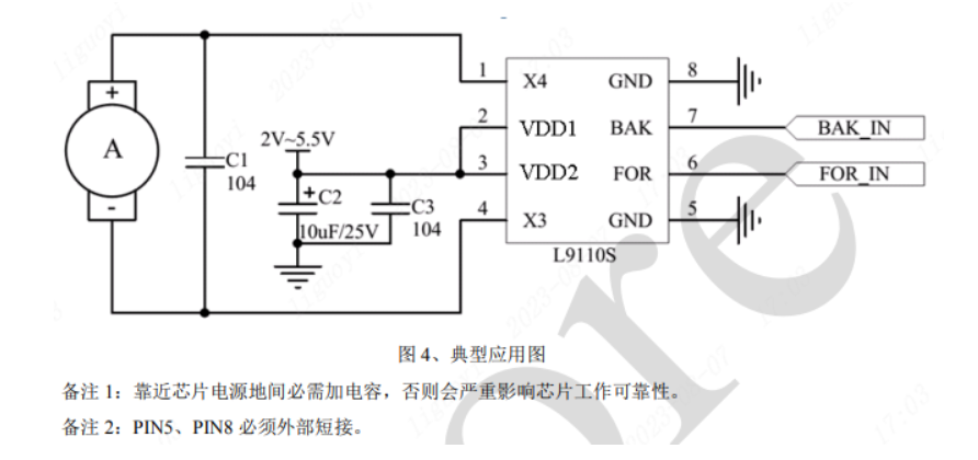
Using a magnetic motor, the higher the current, the stronger the magnetic force. Although it's possible to directly control the stepper motor using the development board's GPIO, there's a risk of damaging the board's pins. Therefore, we need to consider a suitable stepper motor driver, such as the L9110S motor driver chip.
4. Infrared reception:
Electromagnetic waves with wavelengths from 750nm to 1000um in the spectrum are called infrared radiation, which is invisible light. Currently, almost all commonly used household appliances can be controlled via infrared remote control, such as televisions, air conditioners, and projectors. This technology is widely used, and the corresponding components are very inexpensive, making infrared remote control an ideal control method for our everyday devices. Infrared light is emitted in the form of pulses at a specific frequency. After receiving the signal, the receiving end decodes it according to the agreed protocol to complete the data transmission. In consumer electronics, the pulse frequency generally uses the 30kHz to 60kHz band, and the NEC protocol frequency is 38kHz. This transmission at a specific frequency can be understood as turning on a light. Don't be intimidated by the complex terminology; it's simply controlling the blinking frequency (on and off) of a light, just like when you first learn to make a blinking light using a microcontroller, only with a different type of light.
A complete NEC protocol transmission includes: a preamble, an 8-bit address code, an 8-bit address inverse code, an 8-bit command code, and an 8-bit command inverse code.

The preamble consists of a 9ms low level followed by a 4.5ms high level.
The 4 bytes of data consist of an address code, an address inverse code, a command code, and a command inverse code. The inverse code is used to verify correct data transmission and prevent packet loss.
Important: In the NEC protocol, the distinction between 0 and 1 bits is based on the duration of the received high and low levels.
Data transmission 0: 0.56ms low level + 0.56ms high level.
Data transmission 1: 0.56ms low level + 1.68ms high level.
Therefore, the complete time representation of receiving a data bit is as follows:
Data bit 0: 0.56ms low level + 0.56ms high level;
Data bit 1: 0.56ms low level + 1.68ms high level
. The repeat code consists of a 9ms low level and a 2.5ms high level. When an infrared signal is continuously transmitted, it can be sent quickly using the repeat code.
The principle of the infrared receiver module's output level: The infrared receiver outputs a low level when it senses infrared light and a high level when it does not sense infrared light. Therefore, we only need to check whether the OUT terminal outputs a low level to know whether infrared data has been received. There are no special requirements; ordinary GPIO can be used. We select PF7 and configure it to be triggered by the falling edge of an external interrupt.
5. Voice Module:
This design uses the high-performance pure offline voice recognition module HLK-V20/HLK-V20S, newly launched by Hailink Electronics for numerous pure offline control scenarios and products. It can be widely and quickly applied to smart homes, various smart small appliances, toys, lighting, industrial, medical, IoT, automotive, security, and lighting products that require voice control. The module adopts a 32-bit RISC architecture core and incorporates a DSP instruction set specifically for signal processing and voice recognition, supports an FPU unit for floating-point operations, and an FFT accelerator. It trains and learns audio signals through neural networks to improve the voice signal recognition capability. The HLK-V20 supports offline recognition of 150 local commands, while the HLK-V20S supports offline recognition of 50 local commands. Both allow for customization of wake-up words, command words, and response announcements, and feature rich peripheral interfaces.

The Hailingke voice module usage link is
https://lceda001.feishu.cn/docx/LQkZd74b7o8aEHxAGzbcGvHynle
. Publish the edited SDK using the method described above, and download the firmware and download tool after half an hour. Firmware can also be edited on the Smart Park platform.
6. Video Demonstration:
LCSC Training Camp - Smart Curtain Design Based on Liangshan School


 京公网安备 11010802033920号

 KSM-962LM4Y


