What is a battery management system? Analysis of the uses of power management systems
Source: InternetPublisher:两手空空 Keywords: Battery Management System BMS Updated: 2025/02/20
BMS means different things to different people. To some, it is simply battery monitoring, checking key operating parameters such as voltage and current as well as internal battery and ambient temperature during charging and discharging. The monitoring circuits often provide inputs to protection devices that will generate an alarm or disconnect the battery from the load or charger if any parameter is out of limit.
For power or plant engineers responsible for backup power, batteries are the last line of defense against blackouts or disruptions to telecommunications networks, and BMS means battery management system. Such a system includes not only the monitoring and protection of the batteries, but also methods to keep them ready to deliver full power when needed and ways to extend their service life. This includes everything from controlling the charging regime to planning maintenance.
For automotive engineers, battery management systems are components of more complex, fast-acting energy management systems that must interface with other onboard systems such as engine management, climate control, communications and safety systems.
Therefore, there are many varieties of BMS.
Designing Bare Metal Servers
In order to control the performance and safety of batteries, it is necessary to understand what needs to be controlled and why. This requires a deep understanding of basic battery chemistry, performance characteristics and battery failure modes, especially lithium battery failure. Batteries cannot be simply viewed as black boxes.
BMS building blocks
All battery management systems have three common goals
Protect cells or batteries from damage
Extend battery life
Maintain the battery in a condition where it can meet the functional requirements of the specified application.
To achieve these objectives, BMS may incorporate one or more of the following functions. (Click on the links to see how these functions are implemented.
Protecting the battery from out-of-tolerance operating conditions is fundamental to all BMS applications. In practice, the BMS must provide comprehensive cell protection to cover nearly all possible eventualities. Operating the battery outside of the specified design limits will inevitably lead to battery failure. Besides the inconvenience, the cost of replacing the battery can be prohibitive. This is especially true for high voltage and high power automotive batteries that must operate in harsh environments while being susceptible to abuse by the user.
Charge Control This is an essential function of a BMS. More batteries are damaged by improper charging than by any other reason.
While not directly related to the operation of the battery itself, demand management refers to the application in which the battery is used. The goal is to minimize the current draw from the battery by designing power-saving techniques into the application circuit, thereby extending the time between battery charges.
Soil Organic Carbon DeterminationMany applications require knowledge of the state of charge (SOC) of a battery or individual cells in a battery chain. This may simply be to provide the user with an indication of the remaining capacity in the battery, or it may be necessary in a control circuit to ensure optimal control of the charging process.
SOH Determination of State of Health (SOH)
A measure of a battery's ability to deliver its specified output. This is critical in assessing the preparedness of emergency power equipment and is an indicator of whether maintenance action is required.
Cell BalancingIn a multi-cell battery chain, small differences between cells due to production tolerances or operating conditions tend to amplify with each charge/discharge cycle. Weaker cells are overstressed during charging, causing them to become even weaker until they eventually fail, leading to premature battery failure. Cell balancing is a method of compensating for weaker cells by equalizing the charge on all cells in the chain, thereby extending battery life.
history -
(Log Function) Monitoring and storing the battery's history is another possible function of the BMS. This is necessary in order to estimate the battery's health and also to determine if it has been abused. Parameters such as number of cycles, maximum and minimum voltage and temperature, and maximum charge and discharge current can be recorded for subsequent evaluation. This can be an important tool in evaluating warranty claims.
Authentication and identification The BMS also allows information about the battery to be recorded, such as the manufacturer’s model name and battery chemistry, which facilitates automated testing, as well as the batch or serial number and manufacturing date to enable traceability in the event of a battery failure.
Most BMS systems integrate some form of communication between the battery and the charger or test equipment. Some link to other systems that interface with the battery to monitor its condition or history. Communication interfaces are also required to allow the user to access the battery to modify BMS control parameters or perform diagnostics and testing.
The following examples illustrate three distinct practical applications of a BMS.
Smart Battery
The life of rechargeable NiCd and NiMH batteries, such as those used in power tools, can be extended by using an intelligent charging system that facilitates communication between the battery and the charger. The battery provides information about its specifications, current condition, and usage history, which the charger uses to determine the optimal charging curve or to control its usage by the application using the battery.
The main goal of the charger/battery combination is to allow for a wider range of protection circuits to prevent overcharging or damage to the battery, thus extending its life. Charge control can be in the battery or the charger. The purpose of the application/battery combination is to prevent overload and save the battery. Similar to the charger combination, discharge control can be in the application or in the battery.
While some special batteries have been developed that incorporate intelligence, the intelligence is more likely to be implemented in the battery pack.
The system works as follows:
Smart batteries or intelligent batteries provide outputs of sensors that provide the actual state of voltage, current and temperature within the battery as well as the state of charge. It can also provide alarm functions to indicate out of tolerance conditions.
Smart batteries also contain a memory chip which is programmed by the manufacturer and contains information about the battery specifications such as:-
Manufacturing data (name, date, serial number, etc.)
Cytochemistry
Battery capacity
Mechanical shape code
Voltage upper and lower limits
Maximum current limit
Temperature Limits
Once the battery is in use, the memory may also record:-
The number of times the battery is charged and discharged.
Elapsed time
Internal impedance of the battery
The temperature curve it withstands
Operation of any forced cooling circuit
Any situation where the limit is exceeded.
The system also requires devices, perhaps located in the battery or charger or both, that can interrupt or modify charging based on a set of rules. Similarly, battery discharge can be controlled by battery or demand management circuits in the application.
A smart battery also requires a smart charger that it can talk to and a language it can speak.
The charger is programmed to respond to input from the battery to optimize the charging profile, charging at a maximum rate until a preset temperature is reached, then slowing or stopping charging and/or turning on a cooling fan to avoid exceeding temperature limits and thus causing permanent damage to the battery. If the battery's internal impedance deteriorates indicating a need for repair, the charger can also be programmed to reform the battery by subjecting it to several deep charge, discharge cycles. Because batteries contain information about their specifications that can be read by chargers, it is possible to build universal chargers that automatically adapt charging profiles to a range of battery chemistries and capacities as long as they conform to an agreed-upon message protocol.
A separate communication channel is needed to facilitate the interaction between the battery and the charger. An example for simple applications is the System Management Bus (SMBus), which forms part of a smart battery system, primarily used in low-power applications. Batteries that comply with the SBS standard are called smart batteries. However, smart batteries are not limited to the SMS scheme, and many manufacturers have implemented their own proprietary schemes, which may be simpler or more complex, depending on the requirements of the application.
Using this technology is said to extend battery life by 50%.
Automatic control system
This is an example of an automatic control system where the battery provides information about its actual condition to the charger, which compares the actual condition to the desired condition and generates an error signal which is used to initiate a control action to bring the actual condition into line with the desired condition. The control signal forms part of a feedback loop which provides automatic compensation to keep the battery within the desired operating parameters. It does not require any user intervention. Some form of automatic control system is an important part of any BMS
Battery Monitoring
In addition to communicating with the charger, a smart battery can also communicate with the user or other systems the battery may be part of. The signals it provides can be used to turn on warning lights or notify the user of the battery's condition and remaining charge.
Monitoring the battery condition is an essential component of any battery management system. In the first of the two examples below, the control operation is manual, - the power plant maintenance engineer fixes any defects. In the second example, the battery is part of an automated control system consisting of several interconnected feedback loops controlling the battery itself and its role as part of the overall vehicle energy management system.
Power Plant Battery Management System
The battery management requirements for backup and emergency power installations are quite different. The batteries may be inactive for long periods of time, being trickle charged from time to time, or, as in telecommunications installations, they may be kept on a float charge to always remain fully charged. By their nature, such installations must be available at all times. A fundamental duty in managing such installations is to know the state of the battery and whether it can be relied upon to support the load during a power outage. To this end, it is essential to know the SOH and SOC of the battery. In the case of lead-acid batteries, the SOC of a single cell can be determined by measuring the specific gravity of the electrolyte in the battery using a hydrometer. Traditionally, the only way to determine the SOH is a discharge test, that is, by completely discharging the battery and measuring its output. Such a test is very inconvenient. For large installations, it may take eight hours to discharge the battery and three days to recharge it. During this period, the installation will be without emergency power unless a backup battery is provided.
Modern methods of measuring battery SOH are impedance testing or conductance testing
It has been found that the impedance of a cell is inversely correlated to SOC, while conductance, which is the inverse of impedance, has a direct correlation to the cell’s SOH. Both of these tests can be performed without discharging the battery, but even better, the monitoring equipment can remain in place, providing permanent online measurements. This enables plant engineers to have an up-to-date assessment of the battery’s condition in order to detect any deterioration in battery performance and plan appropriate maintenance measures.
Automotive Battery Management System
Automotive battery management is much more demanding than the previous two examples. It must interface with many other onboard systems, and it must work in real time under rapidly changing charging and discharging conditions.
It must operate in a harsh and uncontrolled environment as the vehicle accelerates and brakes. This example describes a complex system to illustrate the possible functionality, but not all applications require all of the features shown here.
The functions of BMS for hybrid electric vehicles are as follows:
Monitor the condition of the individual cells that make up the battery
Keep all batteries within operating range
Protect cells from out-of-tolerance conditions
Provides a “fail-safe” mechanism in the event of uncontrolled conditions, loss of communications, or misuse
Isolating the battery in an emergency
Compensate for any imbalance in battery parameters in the battery chain
The battery operating point is set to allow regenerative braking charge to be absorbed without overcharging the battery.
Provides information about the battery's state of charge (SOC). This feature is often called a "fuel gauge" or "gas gauge."
Provides information about the battery's state of health (SOH). This measurement indicates the condition of a used battery relative to a new one.
Providing information for driver displays and alerts
Predict the possible range of the battery with the remaining charge (only needed for electric vehicles)
Receive and implement control instructions from relevant vehicle systems
Provides optimal charging algorithm for battery charging
Provides pre-charge to allow load impedance testing before turn-on and two-stage charge to limit inrush current
Provides access to charge a single battery
Responding to changes in vehicle operating modes
Recording battery usage and abuse. (frequency, magnitude and duration of out-of-tolerance conditions) is called logging function
Emergency "limp home mode" in case of battery failure.
Therefore, in a real system, the BMS can include more vehicle functions than just managing the battery. It can determine the required operating mode of the vehicle, whether it is accelerating, braking, idling or stopping, and implement the relevant power management actions.
Cell protection
One of the main functions of a battery management system is to provide the necessary monitoring and control to protect the battery from out-of-tolerance environmental or operating conditions. This is particularly important in automotive applications due to the harsh operating environment. In addition to individual cell protection, automotive systems must also respond to external fault conditions by isolating the cell and addressing the cause of the fault. For example, if the battery overheats, the cooling fan can be turned on. If the overheating becomes too hot, the battery connection can be disconnected.
Protection methods are discussed in detail in the Protection section.
Battery State of Charge (SOC)
Determining the battery's state of charge (SOC) is the second major function of a BMS.
Not only used to provide a fuel gauge indication. The BMS monitors and calculates the SOC of each cell in the battery to check for even charging across all cells to verify that individual cells are not overstressed.
The SOC indication is also used to determine the end of the charge and discharge cycle. Overcharging and over-discharging are the two main causes of battery failure, and the BMS must maintain the battery at the required DOD.
within operating limits.
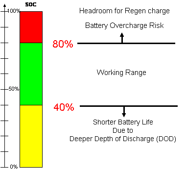
Hybrid vehicle batteries require both high-power charging capability for regenerative braking and high-power discharge capability for launch assist or boost. For this reason, their batteries must be maintained at an SOC that can discharge the required power, but still have enough margin to accept the necessary regenerative power without risking overcharging the battery. Fully charging the HEV battery to balance the cells (see below) reduces the charge acceptance capacity for regenerative braking, thereby reducing braking efficiency. The lower limit is set to optimize fuel economy and prevent excessive discharge, which can shorten battery life. Therefore, HEVs require accurate SOC information to keep the battery operating within the required safety range.
Hybrid vehicle battery operating range
Battery Management System (BMS)
Bare Metal Server Scope and Failure Consequences
The following figure shows possible battery failure mechanisms, consequences and necessary actions that the battery management system should take
Cellular malfunctions, consequences, and protective mechanisms
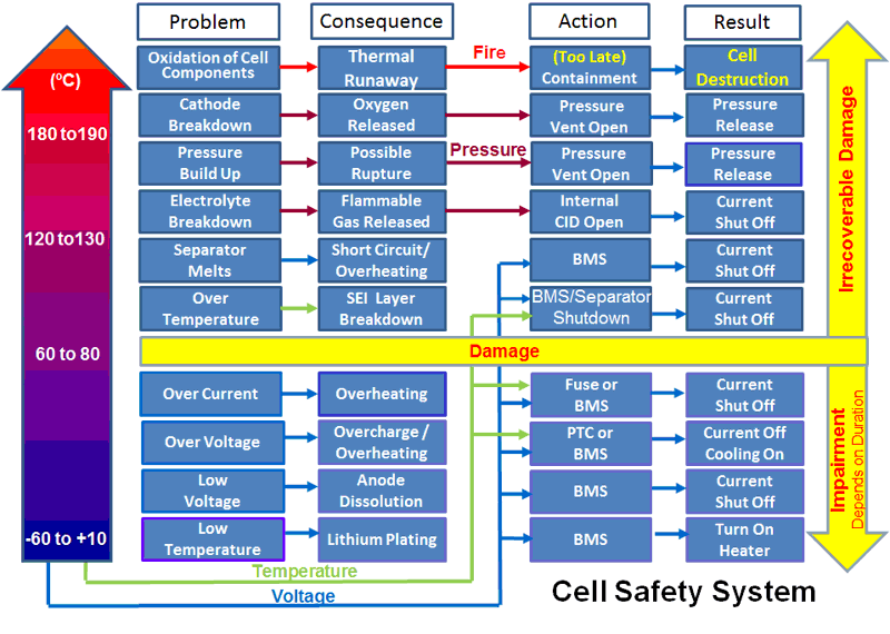
The BMS must protect the battery and the user under all of these conditions
Multi-level security system
The BMS is part of a multi-level safety system with the following objectives and safeguards:
Intrinsically safe cell chemistry
Battery Technology Design Review
Cell supplier and production audit
Technical skills of staff
Process Control (installed and working)
Battery level (internal) safety devices
Circuit Interrupting Device (CID) disconnects the circuit if the internal pressure limit is exceeded
Close the separator
Pressure exhaust valve
External circuit components
PTC resistors (low power applications only)
Fuse
Battery and cell isolation. Electrical and mechanical separation (contactors and physical separation) to prevent event propagation
Bare Metal Server Software
Monitoring of all key indicators combined with control actions. (Cooling, power disconnection, load management)
Control operation or shut down if limits are exceeded
BMS Hardware - Fail-Safe Backup
Shut down the hardware in case of software failure. Set to a slightly higher limit
Low voltage BMS battery shutdown during power failure
contain
Sturdy outer container with controlled ventilation
Physical barriers between cells
Bare Metal Server Implementation
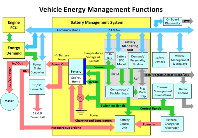
The following figure shows the main BMS
Conceptual representation of functionality. It shows the three main BMS building blocks, the Battery Monitoring Unit (BMU), Battery Control Unit (BCU) and the CAN bus vehicle communication network, and how they interface with other vehicle energy management systems. Other configurations can be achieved with a distributed BMS embedded in the cell-to-battery interconnect.
In practice, the BMS may also be coupled to other vehicle systems that communicate with the BMS via the CAN bus (see below), such as a thermal management system or an anti-theft device that disables the battery. System monitoring and programming may also be required, as well as the use of
RS232 serial bus for data logging.
Battery Monitoring Unit
The battery monitoring unit is a microprocessor-based unit that contains three functions or submodules. These submodules are not necessarily separate physical units, but are shown separately here for clarity.
Battery Model
The battery model characterizes the behavior of the battery in response to various external and internal conditions in a software algorithm. The model can then use these inputs to estimate the state of the battery at any moment in time.
A basic function of the battery model is to calculate the battery SOC for the above functions.
SOC is basically determined by integrating the current over time, modified to account for the many factors that affect battery performance, and then subtracting the result from the known capacity of a fully charged battery.
Detailed description is given in the section.
Battery models can be used to record past history for maintenance purposes, or to predict how many miles a vehicle can travel before the battery needs to be recharged. The remaining range is calculated based on recent driving or usage patterns, and the range is based on current
The SOC is calculated from the energy consumed and the distance covered since the last charge (or based on a long-term average from the past). The driving distance comes from data provided by other sensors on the CAN bus (see below).
The accuracy of the range calculation is even more important for electric vehicles where the only power source is the battery. HEVs and bicycles have another power source to "get you home" if the battery is completely discharged.
The problem of losing all power when a single battery fails can be mitigated by adding four more expensive contactors, which effectively split the battery into two separate units. If a battery fails, the contactors can isolate and bypass the half of the battery containing the failed cell, allowing the vehicle to limp home at half capacity using the other (good) half.
The output of the model is also sent to the vehicle display using the CAN bus.
Multiplexing
To reduce costs, battery monitoring units use a multiplexed architecture that switches the voltage of each cell (input pair) sequentially to a single analog or digital output line (see below), rather than monitoring each cell in parallel. Cost savings can be achieved by reducing the amount of analog control and/or digital sampling circuitry, thereby minimizing component count. The disadvantage is that only one cell voltage can be monitored at a time. A high-speed switching mechanism is required to switch the output line to each cell so that all cells can be monitored sequentially.
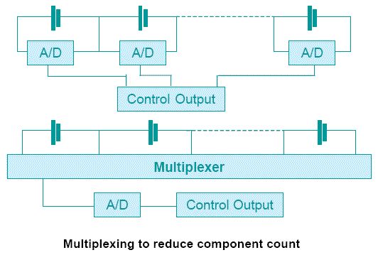
The BMU also provides inputs for estimating the battery SOH, but since the SOH changes only gradually over the life of the battery, less frequent sampling is required. Depending on the method used to determine the SOH, the sampling interval may be as low as once a day. For example, impedance measurements can even be taken when the vehicle is not in use. Of course, cycle counting can only be done when the vehicle is in operation.
Requirements or personality modules
The Demand module is similar in some ways to the battery model in that it contains a reference model that contains all the tolerances and limits associated with the various parameters monitored by the battery model.
The module also receives data from the communication bus (e.g. from the BMS
The device receives instructions for regenerative braking charging (from commands from the ECU), or from other vehicle sensors (such as safety devices) or directly from the vehicle operator. The device is also used to set and monitor vehicle operating mode parameters.
This module is sometimes called a personality module because it includes provisions for programming the system, all custom requirements that may be specific to the customer's application. For example, the battery manufacturer will recommend a temperature limit at which the battery must be automatically disconnected for safety reasons. However, the car manufacturer may set two lower limits, one that turns on forced cooling and the other that illuminates a warning light on the driver's dashboard.
For HEV applications, the personality module interfaces with the engine electronic control unit (ECU) via the CAN bus. Parameters for setting the desired system SOC operating range and for controlling the power sharing between the electric drive and the internal combustion engine are specified in this module.
The Demand module also contains a storage block to save all reference data and accumulate them for monitoring battery SOH
The data showing SOH or turning on the warning light can be provided to the vehicle instrument module via the CAN bus.
The output of the demand module provides a reference point for setting the operating conditions of the battery or triggering the action of a protection circuit.
Test access to the BMS is provided via a standard RS 232 or RS485 serial bus for monitoring or setting system parameters and downloading battery history.
Decision logic module
The decision logic module compares the state of the battery parameters measured or calculated in the battery model with the desired or reference results of the demand module. The logic circuit then provides error messages to initiate battery protection actions or for various BMS feedback loops to drive the system to the desired operating point or isolate the battery in unsafe conditions. These error messages provide input signals for the battery control unit.
System Communication
The BMS requires a communication channel for passing signals between its various internal functional circuit modules. It must also interface with multiple external vehicle systems to monitor or control remote sensors, actuators, displays, safety interlocks, and other functions.
Therefore, the automotive BMS uses the CAN bus designed for this purpose as its main communication channel.
The system should also include provision for standard automotive on-board diagnostics (OBD) and provide diagnostic trouble codes (DTCs) to the service engineer. This connection is important in identifying any external causes of battery failure.
Battery Control Unit
The battery control unit contains all the BMS power electronic circuits. It takes control signals from the battery monitoring unit to control the battery charging process and switch the power connection to the individual batteries.
Some possible functions of this unit are:
Control the voltage and current curves of the charger output during the charging process.
Provides charge to a single cell to balance the charge of all cells in the battery chain.
Isolate the battery during a fault or alarm condition
Switches regenerative braking charging to the battery as needed
Dumping excess regenerative braking charge when the battery is fully charged
Responding to changes in vehicle operating modes
To provide these functions, each cell in the battery may require expensive high current switches capable of switching 200 amps or more to provide the necessary interconnections.
Binary control and progressive control
In its simplest form, a BMS provides a "binary" ON/OFF response to out-of-tolerance conditions such as a fault or overload, completely isolating the battery by simply opening the main contactor. However, in the event of an overload, it is possible to provide progressive or variable control by utilizing the CAN bus to reduce demand on the battery.
Cell Balancing
This is another essential function of an automotive BMS. As mentioned above, it is necessary to compensate for the weaknesses of individual cells, which may eventually lead to failure of the entire battery. The reasons for cell balancing and how it is achieved are explained on the Cell Balancing page.
Limp Home Mode
Although batteries are designed to be trouble-free for 3 years or more, there is always a chance that a battery could fail due to a single cell failure. If a cell has an open circuit, the battery is essentially dead. However, a BMS is designed to monitor the status of each cell, so the location of the failed cell will be automatically identified. It is not difficult to split the battery series into two sections, each of which can be bypassed independently by disconnecting the battery section containing the failed cell and switching a conductive link in its place. This will allow the vehicle to reach home or the nearest shelter at half power using the good portion of the battery. In addition to the link, the system would require two more expensive high-power contactors to achieve this function, but this investment may be justified when the alternative may be an expensive and dangerous breakdown on the highway.
System Enhancements
The automotive BMS may also need to provide various functions that are not necessarily required to manage the battery. These may include remote monitoring of the battery from the fleet headquarters, which may also include the GPS location of the vehicle. Therefore, if the vehicle is low on charge or strays too far from a charging station, the driver can be warned.
Fortunately, not all BMS applications are as complex as this one.
Practical BMS Implementation
There are many ways to implement a battery management system, two different examples are shown below for an 80 volt battery consisting of 256 lithium iron phosphate cells.
Master-Slave
Master and Slave, Star topology, organizes the units into blocks or modules, each managed by a slave. In the example shown, 16 X 3.2 volt batteries are arranged in modules, each module has an output voltage of
51.2 volts, but other module sizes and voltages are possible.
Slaves - Each cell has a temperature sensor as well as connections for measuring voltage, all of which are connected to the slaves, which monitor the condition of the cells and enable cell balancing.
Master - Multiple slaves can be connected to the master, which monitors the current and integrates it over time to calculate the net coulomb flow, and modifies it with voltage and temperature data from the slaves to calculate the battery SOC. The master controls the main battery isolation contactor to initiate battery protection in response to data from the master current sensor or voltage and temperature data from the slaves. The master also provides system communications.
BMS Master and Slave (Star Topology)
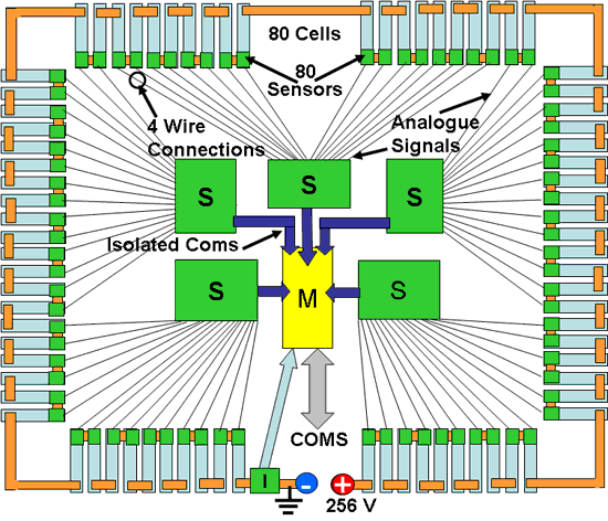
The advantages of this configuration are that no printed circuit board needs to be connected to the individual cells, and high voltage batteries can be accommodated by adding more modules, and since the master battery current does not pass through the slave, it can also be used for high current batteries. Signal processing is shared between the master and slaves, simplifying the management of the information processing load. Internal communications are done via
I2C bus.
The disadvantages are that the communication between the sensor and the slave is analog and therefore susceptible to noise, and a large number of sensor wires are required, four per unit. An optically isolated connection between the slave and the master is also required, as the voltage on the slave will gradually rise to the full battery voltage as the connection is taken from upstream in the battery chain.
Communications with the outside world (COMS in the pictures above and below) are usually via an RS232 or more likely USB serial connection.
BMS Daisy Chain
A daisy-chain, ring topology uses a small, simple slave PCB connected to each cell to house voltage and temperature sensors with A-to-D converters, a current bypass switch to enable cell balancing by charge shunting, and a communications transceiver with built-in capacitive isolation for receiving and transmitting data in digital form. The slave draws power from the cell it is monitoring, with a single RS
The 485 three-wire data bus connects all the slave nodes to the master, which polls each node in turn and requests an update on its unit condition. The slave does not perform any signal processing other than A to D conversion, as this is all performed by the master, as well as all the monitoring, protection and communication functions in the example above.
BMS Daisy Chain (Ring Topology)
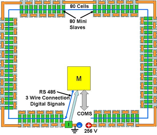
The main advantages of this topology are its simpler design and construction, and the potential for higher reliability in an automotive environment.
The disadvantages are the large number of mini slave PCBs required and the difficulty of mounting them on some battery types. Also, the master has a higher processing load.
- Redundancy principle of power management system, a redundant design strategy in outdoor power BMS
- How to improve the accuracy and precision of power supplies through low frequency thermal noise?
- Offline 8w LED Flyback Power Supply with PFC using NCP1014
- Constant current LED lamp driver circuit with soft start and anti-shock
- How to use SBR to improve power conversion efficiency
- A small and easy-to-make fast charger
- A novel and practical DC low voltage stabilized power supply
- An ultra-low output voltage regulator
- Car power 1.5V-12V six-speed converter
- Self-made high-stability, high-current, DC adjustable voltage-stabilized power supply using operational amplifier
- Laser power circuit
- Power circuit with smoothing filter capacitor
- Warm current power circuit a
- Simple dual-channel variable DC power supply circuit
- DC power supply circuit for semiconductor radio
- ±15V active servo power circuit
- Practical neon light power circuit
- Common power circuits and applications 07
- Common power circuits and applications 03
- COMPAQ 420G type SVGA color display power supply circuit


 京公网安备 11010802033920号