TL431 functional pin diagram, DC linear regulated power supply solution based on TL431
Source: InternetPublisher:他们逼我做卧底 Keywords: TL431 three-terminal voltage regulator linear regulated power supply Updated: 2025/02/20
TL431 is a three-terminal controllable precision reference integrated chip with good temperature stability. It has the characteristics of small size, accurate voltage, excellent performance and low price. It is widely used in constant current source circuits, voltage comparison circuits, voltage monitoring circuits, low voltage protection circuits, overvoltage protection circuits, linear voltage regulator power supply circuits, switching power supply circuits, reference voltage circuits, etc.
TL431 Internal Structure
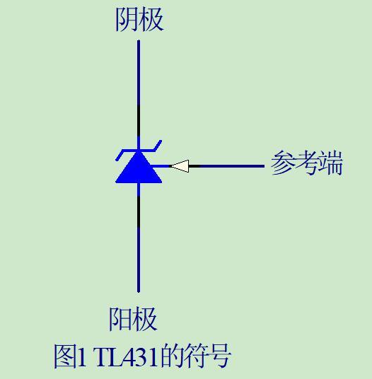
The symbol of the device is shown in Figure 1. The three pins are: cathode (CATHODE), anode (ANODE) and reference terminal (REF), and the reference voltage is 2.5V.
TL431 functional pin diagram
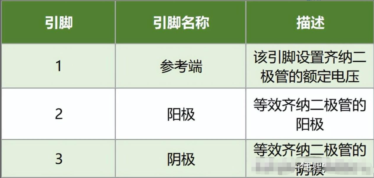
Some people may ask how to distinguish the three pins of TL431? Look at the picture below, with the logo facing you, from left to right: reference terminal, anode, cathode.
The following 2 pictures are: TL431 functional pin diagram

DC linear regulated power supply solution based on TL431
The following is a DC linear voltage regulated power supply solution based on TL431. After adjusting the reasonable parameters of the circuit, it can be used in a variety of DC power supply circuits.
1. Precision reference power supply circuit
The following figure shows two typical connection methods when TL431 is used as a reference voltage source. TL431 contains a 2.5V reference voltage inside. If the output voltage (VO) is directly introduced into the ref pin (pin 1), the output voltage is 2.5V; if the output voltage is divided and then fed back to the ref pin (pin 1), the output voltage can be set to any reference voltage between 2.5V and 36V. Typical value: When R1=R2, VO=5V. It should be noted that when selecting resistors R1 or R2, the necessary conditions for the operation of TL431 must be guaranteed, that is, the current passing through the cathode must be greater than 1ma. The voltage divider resistors R3R4 are simple precision resistors, and the total resistance value can range from a few K to hundreds of K. VO=2.5 (1+R3/R4)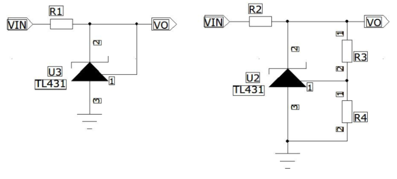
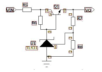
2. Series voltage regulator circuit
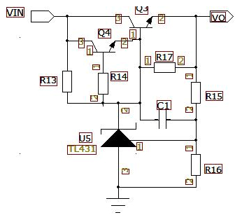
The first figure below is a series voltage regulator circuit based on TL431. This circuit uses the Q1 transistor to expand the current, which can increase the output current of the entire circuit, while reducing the power of the R5 current limiting resistor. Its output voltage is obtained by the ratio of the voltage divider resistors R7 and R8. The amplification factor of Q1 is mainly determined by R6, so setting a suitable R6 can increase the overcurrent capacity of Q1. VO=2.5(1+R7/R8)
Sometimes, in order to increase the current and reduce the maximum power of the current limiting resistor, we can also use Darlington transistors to expand the current, as shown below:
When using, you must pay attention to selecting the appropriate transistor and provide reasonable heat dissipation for the transistor.
3. Parallel voltage regulator circuit
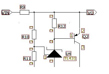
The circuit shown in the figure below is based on the parallel voltage regulator circuit of TL431. The output current is adjusted by parallel connection of Q2 transistor, and the output voltage is reduced or increased accordingly. The corresponding current limiting resistor R9 is also selected with a resistor of sufficient power to achieve the maximum power requirement. This circuit is generally used in overvoltage protection circuits or voltage limiting circuits, and is commonly seen in lithium battery balancing circuits.
- How to ensure the stable performance of SSD when the voltage is unstable?
- What is a battery management system? Analysis of the uses of power management systems
- 5 Converter Topologies for Integrated Solar and Storage Systems
- Schematic diagram of car cigarette lighter to USB power port
- Brief Analysis of the Working Principle of AC Voltage Stabilizer Circuit
- Switching power supply circuit composition and function introduction of each part
- Current/voltage conversion circuit using current converter
- 3~15V 10A adjustable voltage regulated power supply
- Mc34063 MP3 Switching Charger
- The production of adjustable voltage-stabilized power supply composed of LM317
- Use TL431 to make a TTL logic level detection circuit
- 3v to 5v circuit diagram
- Single phase thyristor slotless nickel plated power circuit
- Transistor stabilized current power supply circuit 2
- Simple dual-channel variable DC power supply circuit
- Switching regulator composed of TL431
- Overvoltage protection circuit diagram using TL431 precision reference source, etc.
- Using TL431 to form a switching regulated power supply circuit diagram
- Parallel regulated power supply circuit diagram using TL431
- Basic application circuit diagram of TL431 b Adjustable quasi-source circuit diagram


 京公网安备 11010802033920号