How to solve the problem when MAX485/RS485 overheats and stops working when driven by a microcontroller?
Source: InternetPublisher:风向双子座 Keywords: RS485 max485 MCU driver Updated: 2025/02/20
After using a microcontroller to drive the MAX485 and RS485 chips for a while, have you ever encountered the situation where these two chips are burned or stop working? If your answer is "yes", then you have come to the right place. You can solve this problem by simply following the following methods.
Microcontroller development engineers said that usually MAX485 or RS485 can work normally, even in some special environments. But after a while you will find that the circuit that was just working fine suddenly stops working properly, just like it stops sending data or stops receiving data.
After much research, I found that there are many reasons why this may happen, but just make sure you follow the guidelines below and the circuit will work properly.
1. RS485 requires common grounding
Many people usually think that RS485 is a differential bus, so only two wires are needed to work, because the receiver can compare the two voltages. Microcontroller development engineers say that this idea is actually wrong, and all RS485 common lines must be grounded.
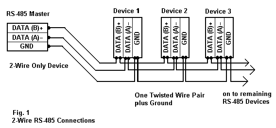
If you do not connect the common ground, the RS485 driver may be damaged at any time even if the circuit is working now. This is because the potential difference between the devices may be high because the ground is not connected, and more current will flow through the A, B wires.
It is worth noting that if you need to isolate the ground, you must use an isolated RS485 driver instead of a regular driver like the MAX485.
2. Power supply
Next, you must ensure that the power supply is good and within the ratings of the RS485 driver. If your power supply is subject to transient noise and spikes, use appropriate capacitors, inductors, TVS diodes, and MOVs to resolve this.
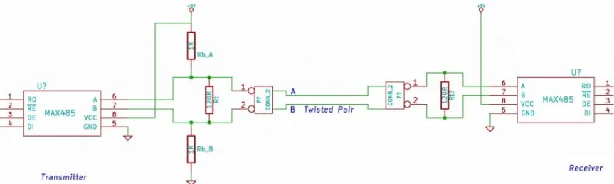
Even though it won't cause any damage to your chip or circuit, we still recommend using a combination of pull-up and pull-down resistors at one location on the bus to solve this problem.
3. Use TVS diode
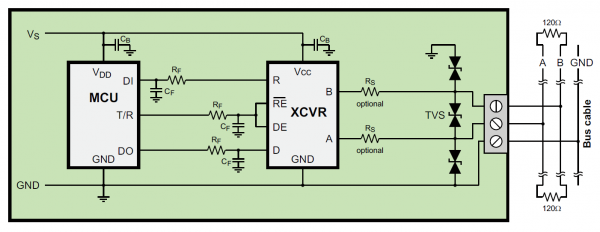
Since RS485 transmission lines are long, it is very common to pick up transient noise. Therefore, it is recommended to use TVS diodes to eliminate common-mode transient voltages between A, B, and GND. Sometimes when used in a high-noise environment, the MAX485 will stop working. However, generally adding a TVS diode to the circuit can solve this problem.
- Improved circuit diagram of 8050 transistor emitter drive relay
- FPGA and DAC0832 interface circuit
- Interface circuit composed of 8051 single chip microcomputer and 74LS165
- How to use ESP8266 to make a mini fully functional clock
- How to make a super solar tracker using ESP8266
- How to control fans using LM35 and ATTiny13
- How to use ESP32 to implement the design of air quality monitoring system
- Application circuit composed of CSJ-R05B and microcontroller
- p4 478 chip pin distribution diagram
- SST89C58 electronic disk circuit and code
- RS485 network transceiver, have you heard of it?
- Photoelectric isolation RS485 typical circuit diagram
- Circuit diagram combining rs232 and rs485
- Ultra-low power transceiver network circuit with RS485 performance
- Circuit combining RS232 and RS485
- RS232-RS485 interface circuit
- A little summary of the operating principles of single-chip microcomputer


 京公网安备 11010802033920号